Physical Address
304 North Cardinal St.
Dorchester Center, MA 02124
This chapter provides several examples of how to crop a real-time three-dimensional (RT3D) image to show a particular structure of interest. Q-lab, a software program developed by Philips Medical Systems, is used in the examples, but other similar software programs are available. One goal of this chapter is to show how to think in three dimensions and how to eliminate unnecessary parts of the 3D dataset to show the structure of interest. The terms “pulling down” and “pushing up” are used to describe how the track ball on the ultrasound machine or a mouse would be moved to rotate the dataset.
In the 3D datasets, the planes are defined as follows:
Red = X plane
Blue = Y plane
Green = Z plane
Figure 17-1 ( Video 17-1 ) shows the starting point.
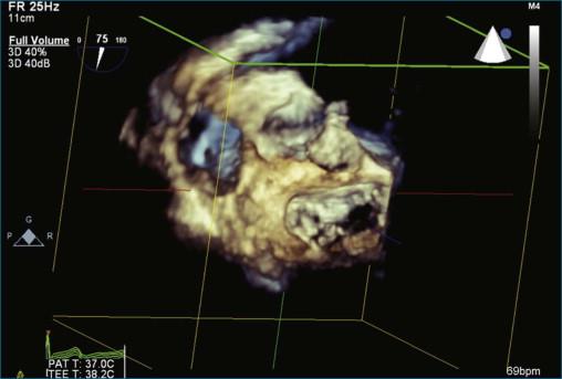
Step 1 ( Figure 17-2 ; Video 17-2 ): Obtain the full volume of the aortic valve. The initial approach is to image the aortic valve in the standard short-axis transesophageal echocardiography (TEE) view. This view typically has the rotational angle at 30 degrees. In this case, the rotational angle is at 75 degrees. When the aortic valve is well visualized, a full volume is obtained.
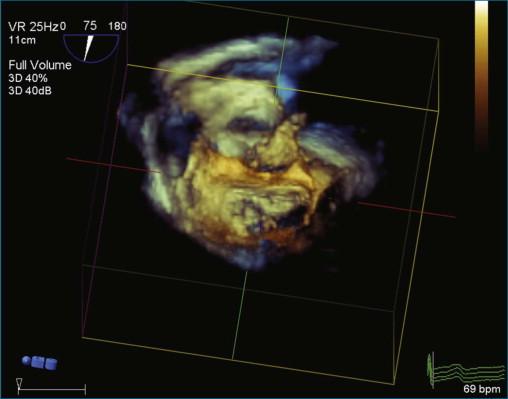
Step 2 ( Figure 17-3 ; Video 17-3 ): After obtaining the full volume, pull the dataset down toward the user with the track ball or mouse.
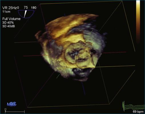
Step 3 ( Figure 17-4 ; Video 17-4 ): Maximize and minimize all the cut planes (X, Y, and Z) to the annulus of the aortic valve cusps.
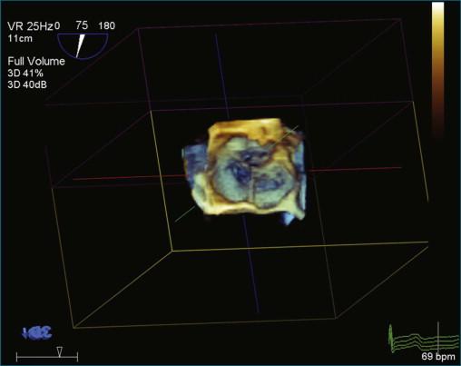
Step 4 ( Figure 17-5 ; Video 17-5 ): Activate “Any Plane” by clicking on “Crop Adjust Plane.” Position “Any Plane” to the upper right corner of the right coronary cusp annulus and slide the plane adjust bar one third to the left.
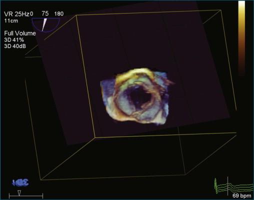
Step 5 ( Figure 17-6 ; Video 17-6 ): Remove the crop box and “Any Plane” by clicking on the “Crop Adjust Plane” button.
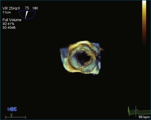
Step 6 ( Figure 17-7 ; Video 17-7 ): Optimize the image by clicking on the “B/W” tab and sliding the Gain, Brightness, Compression, and Smoothing bars until the desired appearance is achieved.
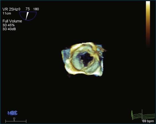
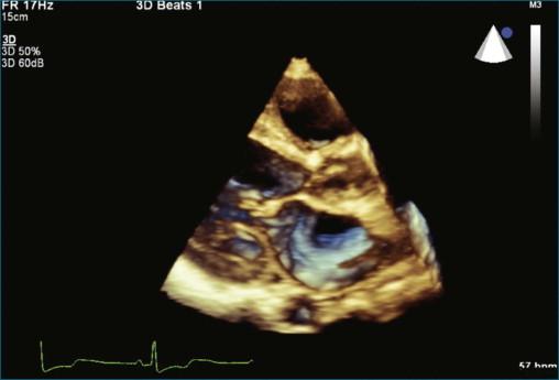
Figure 17-8 ( Video 17-8 ) is a setup view showing parasternal long-axis view of the mitral valve and left atrium.
Become a Clinical Tree membership for Full access and enjoy Unlimited articles
If you are a member. Log in here