Physical Address
304 North Cardinal St.
Dorchester Center, MA 02124
Catheter-based invasive contrast angiography is the standard method for diagnosing peripheral artery disease (PAD), and against which all other methods are compared for accuracy. Angiography provides the “road map” on which therapeutic decisions are based. Knowledge of the vascular anatomy and its normal variations is a core element in the skill set required to safely perform peripheral vascular angiography and interventions.
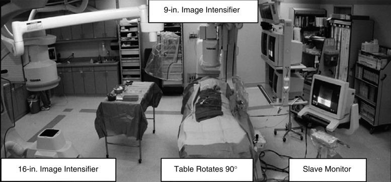
There are many radiographic equipment vendors and many different room layout schemes suitable for performing peripheral vascular angiography. However, if both cardiac and noncardiac types of peripheral vascular angiography are to be performed in the same room, equipment options become much more limited. One angiographic suite designed to perform both coronary and peripheral vascular angiography is a dual-plane system ( Fig. 15.1 ). A dual-plane system economically provides a layout with two independent C-arm image intensifiers operated by a single x-ray generator and one computer. A dual-plane system is not synonymous with a biplane system, which is the simultaneous operation of an anteroposterior (AP) and lateral (LAT) image acquisition system. In a dual-plane system, the cardiac C-arm is a three-mode, 8- or 9- inch flat-panel image intensifier, and the noncardiac C-arm should be as large as possible, usually a 15- or 16-inch flat-panel image intensifier. For peripheral vascular imaging, particularly bilateral lower-extremity runoff angiography, an image intensifier smaller than 15 inches may not be able to include both legs in the same field. The noncardiac C-arm should be capable of head-to-toe digital imaging.

The ability to angulate (rotational as well as cranial and caudal) the image intensifier is necessary to resolve bifurcation lesions and optimally image aorto-ostial branch lesions. Of the many imaging options available, those most often used include digital subtraction angiography (DSA), roadmapping, and a stepping table for lower-extremity (digital subtraction) runoff angiography.
Ionic low-osmolar or nonionic iodinated radiographic contrast is preferred for angiography of the peripheral vessels to avoid patient discomfort. Low-osmolar contrast agents produce fewer side effects (e.g., nausea, vomiting, local pain) and offer better patient tolerability. In addition, low-osmolar agents deliver a lesser osmotic load and thereby a lower intravascular volume, which may be important in patients with impaired left ventricular or renal function. DSA is often preferred because nonvascular structures are removed from the image and less contrast is required. Frequently, it is possible to dilute radiographic contrast 1:1 with saline and still preserve image quality with DSA.
Alternatives to iodine-based radiographic contrast include carbon dioxide (CO 2 ) and gadolinium (gadopentetate dimeglumine). To minimize the risk of distal embolization and stroke, it is recommended that CO 2 not be used for angiograms above the diaphragm. Gadolinium, traditionally used with magnetic resonance angiography, is relatively nontoxic in patients with adequate renal function at a recommended dose not exceeding 0.4 mmol/kg, but provides suboptimal image quality.
Many of the technical aspects of diagnostic cardiac imaging also apply to performing angiography of the aorta and peripheral vasculature. The basic principle of vascular angiography is not only to visualize the target lesion but also to demonstrate the inflow and outflow vascular segments. Inflow anatomy constitutes the vascular segment preceding the target lesion, and outflow constitutes the vascular segment immediately distal to the target vessel and includes the runoff bed. For example, the inflow segment for the common iliac artery (CIA) is the infrarenal aorta, and the outflow segment is the external iliac and femoral vessels. The runoff bed would be the tibioperoneal vessels.
When performing selective arterial imaging, it is important for patients’ safety that a coronary manifold with pressure measurement be used to monitor hemodynamic status and ensure that damping of the catheter has not occurred prior to injecting contrast. The use of pressure monitoring during selective angiography can prevent a myriad of complications, including the creation of dissections and air injection.
Angiography may be performed using a “bolus chase” cineangiographic method or with a digital subtraction stepping mode. The bolus chase technique involves injecting a bolus of contrast at the inflow of the territory, then “panning” or manually moving the image intensifier or table to follow the bolus of contrast through the target lesion and into the run-off segment. The bolus chase technique does not allow for subtraction to occur. In digital subtraction stepping mode, the patient lies motionless on the angiographic table. A “mask” of the segments to be imaged is taken, and then contrast is injected. The table moves in steps to image the contrast-filled vessels, from which the mask is then subtracted, leaving only the contrast-filled vascular structures.
Vascular access for noncardiac diagnostic angiography is most commonly achieved at the common femoral artery (CFA), with alternative upper-extremity sites at the radial, brachial, or axillary artery. For diagnostic, nonselective lower extremity run-off angiography, 4 F catheters inserted into the radial artery and positioned in the infrarenal aorta is becoming more common. The most common complications of angiographic procedures occur at vascular access sites.
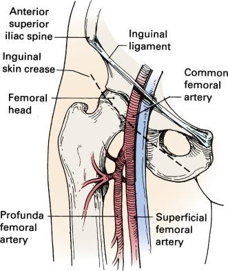
A thorough understanding of the relationship of the CFA to anatomical landmarks is necessary to ensure safe CFA puncture ( Fig. 15.2 ). The femoral artery and vein lie below the inguinal ligament, which is a band of dense fibrous tissue connecting the anterior superior iliac spine to the pubic tubercle. The inguinal skin crease, which is variable in location, is shown as a dotted line in the figure. Current recommendations are to use either fluoroscopic guidance or ultrasound guidance to image the femoral head to guide CFA puncture.

The most important anatomic landmark for femoral arterial access is the head of the femur. In a morphological study using computed tomography (CT) images, there was not a single case in which a puncture would have passed cranial to the inguinal ligament or caudal to the femoral artery bifurcation if the CFA were entered at the level of the center of the femoral head. Caudal to the femoral head, the CFA is encased in the femoral sheath and bifurcates into the superficial femoral artery (SFA) medially and the deep femoral artery (DFA) laterally. With these anatomical observations in mind, the importance of osseous support and entry of the needle into the CFA at the center of the femoral head is obvious.
Anatomical landmarks are initially identified by palpation of the anterior superior iliac spine and pubic tubercle to locate the inguinal ligament; the position of the femoral head is confirmed fluoroscopically. Depending on the amount of subcutaneous fat, a skin incision should be made 1 to 2 cm caudal to the level of the center of the femoral head. The needle is directed in an oblique direction while palpating the CFA over the center of the femoral head. Once the CFA has been entered and brisk blood flow returns through the needle, a soft guidewire is advanced into the iliac artery, and a vascular sheath is inserted to secure vascular access.
For ultrasound-guided CFA access, after sterile draping, the ultrasound probe is used to visualize the femoral bifurcation with a transverse view. With the bifurcation kept in focus, the view is switched to longitudinal, and the femoral bifurcation and femoral head are identified, giving a clear view of the CFA. Keeping the bifurcation at the inferior edge of the screen also aids in avoiding a high puncture. A nick in the skin is made with a No. 11 blade, and the subcutaneous tissue is spread to create a track for the arterial sheath. A micropuncture needle is then inserted under ultrasound guidance, with care taken to see the entire length of the needle as well as the length of the CFA filling the ultrasound screen with the long view. If fluoroscopy demonstrates a puncture above the femoral head, the needle is removed and reinserted lower.
Complications of CFA puncture are most commonly related to arterial entry that is either too high or too low. When the puncture is too high, a retroperitoneal hemorrhage may occur. The presence of loose connective tissue in the retroperitoneal space can lead to large hematomas that can result in life-threatening hemorrhage. Lack of osseous support and the presence of a tense inguinal ligament at the arterial puncture site make manual compression difficult. Low punctures may be complicated by formation of arteriovenous fistulas (AVFs), false aneurysms, and hematomas.
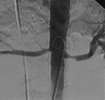
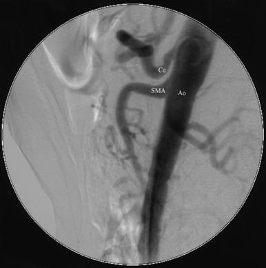
For abdominal aortography, vascular access with a 4 F to 6 F catheter is obtained in the CFA, although brachial or radial access may also be used. The angiographic catheter (e.g., pigtail, tennis racquet, omni flush) is positioned in the abdominal aorta such that the tip of the catheter reaches the level of the last rib. A power injector is used to deliver 20 to 30 mL of contrast at 15 mL/s for digital subtraction ( Fig. 15.3 ). Either biplane angiography may be obtained or, if needed, two separate angiograms with single-plane systems. Three visceral (mesenteric) arterial branches, the celiac trunk, superior mesenteric artery (SMA), and inferior mesenteric artery (IMA), arise from the anterior surface of the abdominal aorta ( Fig. 15.4 ). The renal arteries originate from the lateral aspect of the abdominal aorta at the level of L1 to L2. The AP projection allows visualization of the aorta, renal arteries, and iliac artery bifurcation, whereas the LAT view demonstrates the origin of the celiac trunk and mesenteric arteries. Commonly in the AP view, the proximal portion of the SMA obscures the origin of the right renal artery. When this occurs, selective angiography of the renal artery may be required to visualize the origin of this vessel.


Generally, a nonselective abdominal aortogram is obtained before selective renal angiography, using a large format (9- to 16-inch) image intensifier with digital subtraction imaging. The nonselective aortogram demonstrates the level at which the renal arteries arise, the presence of any accessory renal arteries and their location, the severity and location of aortoiliac pathology, and the presence of significant renal artery stenosis. To optimize viewing of the renal arteries, the angiographic catheter should be placed below the origin of the SMA, and the image intensifier should be positioned such that the superior, inferior, and lateral borders of both kidneys are visualized. The ostia of the renal arteries are often better seen with slight rotation of the image intensifier, usually into left anterior oblique (LAO) position.
Become a Clinical Tree membership for Full access and enjoy Unlimited articles
If you are a member. Log in here