Physical Address
304 North Cardinal St.
Dorchester Center, MA 02124
After the first-in-human transcatheter aortic valve implantation (TAVI) more than 15 years ago, this procedure continues to be developed and refined. This chapter aims to provide the reader with knowledge about TAVI implantation from finding the optimal coplanar view to guidewire placement into the left ventricle, valvuloplasty, and deployment of more used transcatheter aortic valves (TAVs).
To guide precise and safe positioning and deployment of transcatheter bioprostheses, finding the optimal coplanar view of the aortic annulus and the prosthetic valve delivery catheter is of paramount importance. The aortic annular plane and the tip of the delivery catheter should both be visualized perpendicular to the source-to-detector direction. The most important step for determining the release projection is to find the proper alignment of all three aortic cusps in a single plane. Different strategies to accomplish this key step have been proposed; the techniques that are most widely used today are fluoroscopy/angiography and multidetector computed tomography (MDCT).
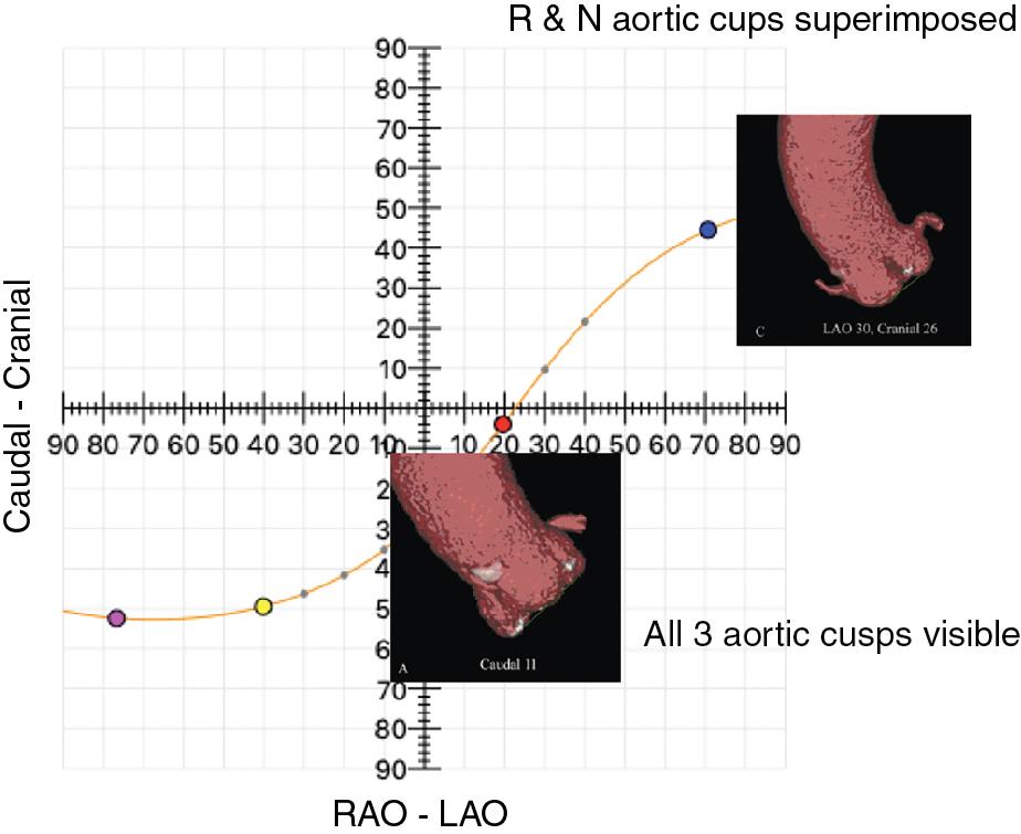
Fluoroscopy represents the large-scale usage tool for the assessment of the release projection in most laboratories. There are infinite angiographic projections in which the three aortic cusps are located on the same plane. These projections follow a sigmoid in which the layout of the cusps at angiography is different:
In the right anterior oblique (RAO)–caudal (CAU) projections, the three cusps will be arranged with the noncoronary cusp (NCC) to the left and the right coronary cusp (RCC) and left coronary cusp (LCC) superimposed to the right.
In anteroposterior (AP) projections, the NCC will be located on the left, the RCC at the center, and the LCC to the right.
In the left anterior oblique (LAO)–cranial (CRA) projections, the NCC and RCC will be overlapped on the left and the LCC on the right ( Fig. 10.1 ).
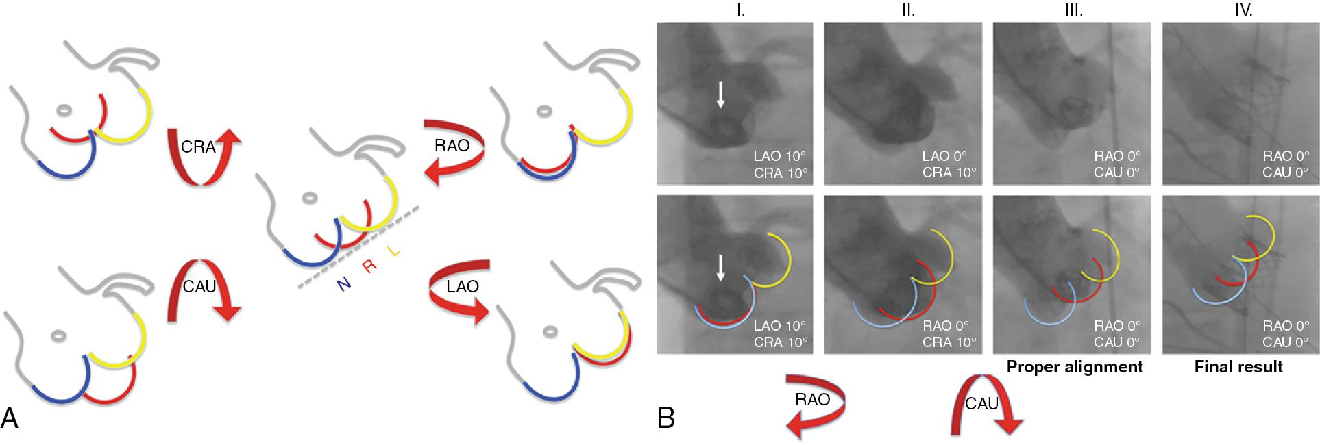
There is a quick and easy rule—“follow the right cusp”—to define the perpendicular annulus plane by fluoroscopy and to obtain the alignment of the RCC between the LCC and the NCC. If the RCC is placed behind the NCC or the LCC, the C-arm must be rotated to an RAO or LAO angulation, respectively. If the RCC appears higher or lower than the ideal plane intercepting other cusps, the x-ray beam should be angulated CRA or CAU, respectively ( Fig. 10.2 ).
With the use of MDCT, assuming that the patient will take the same position on the table of the MDCT and in the catheter laboratory, it is possible to calculate the projection that allows viewing the three aortic cusps on the same plane in an extremely accurate manner. This is the technique that is most widely used today for determining the release projection.
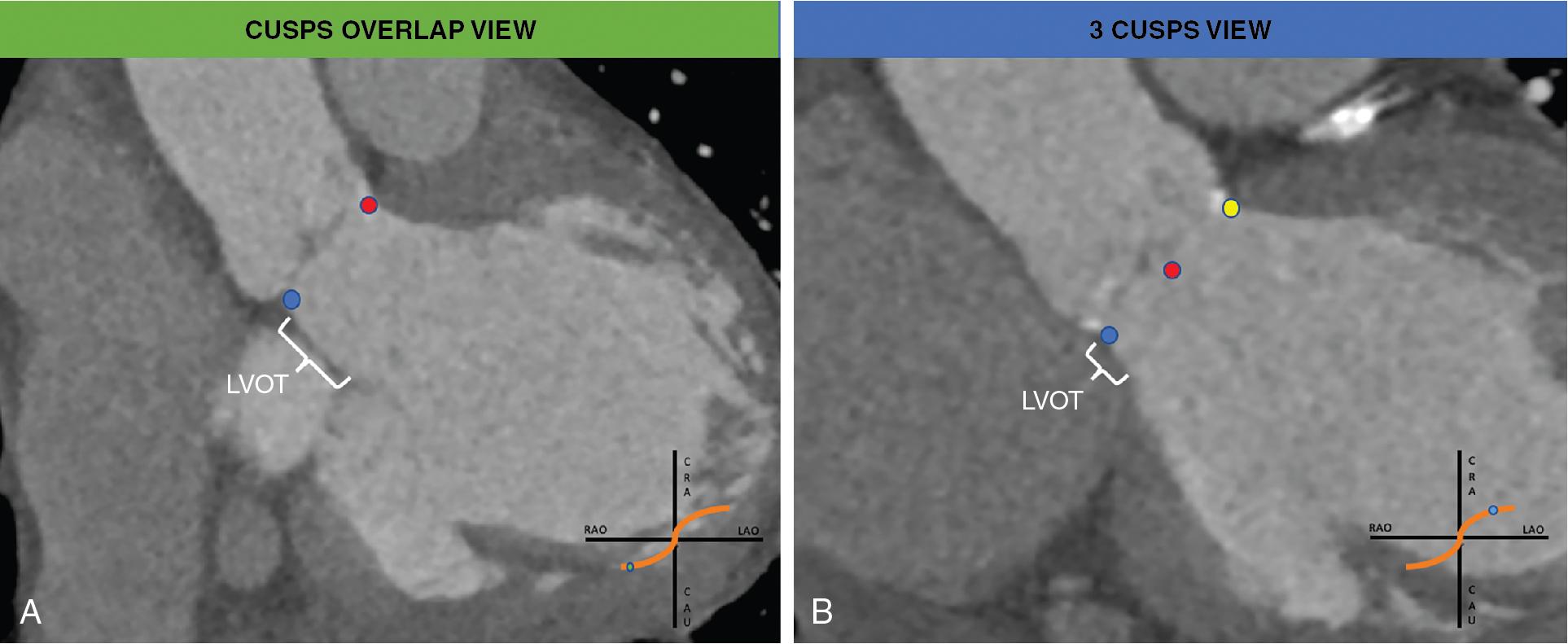
The “three cusps view” has been used for a long time as the reference to deploy the TAV. On one hand, this projection guarantees the visualization of the three cusps at the same distance (usually AP, LAO-CAU); on the other hand, this yields the foreshortening of the left ventricular outflow tract (LVOT). More recently, the “cusps overlap view” ( Fig. 10.3 ) is becoming the standard projection for self-expandable valve (SEV) deployment. Indeed, it allows to elongate the view of the LVOT, providing a more accurate assessment of deployment depth, and it isolates the right-left commissure at the right-hand side of the screen, which allows the operator to align the neo-commissure of the TAV to the native commissure.
Crossing the stenotic aortic valve is a crucial step for placing the guidewire into the left ventricle (LV) in the course of the TAVI procedure.
The following materials are used for this purpose:
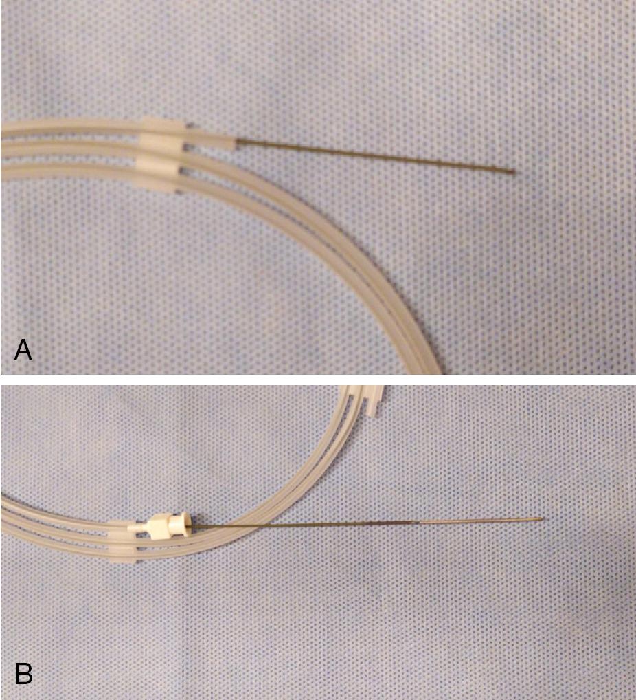
The soft tip straight standard guide. Hydrophilic guides or Teflon-coated straight-tipped guidewires are available. The straight-tipped guidewire is usually preferred because it is easily maneuverable ( Fig. 10.4 ). The length of the soft tip can be adjusted, depending on the operator’s choice or based on the grade of calcification of the valve.
The Amplatz catheter (AL-1). The AL-2 is preferable in the case of aortic ectasia and horizontal aorta; the standard pigtail or angled pigtail in case of dilated aorta; the right Judkins catheter (JR-4) and the multipurpose (MP) catheters can be also used in case of an eccentric opening of the aortic valve ( Fig. 10.5 ).
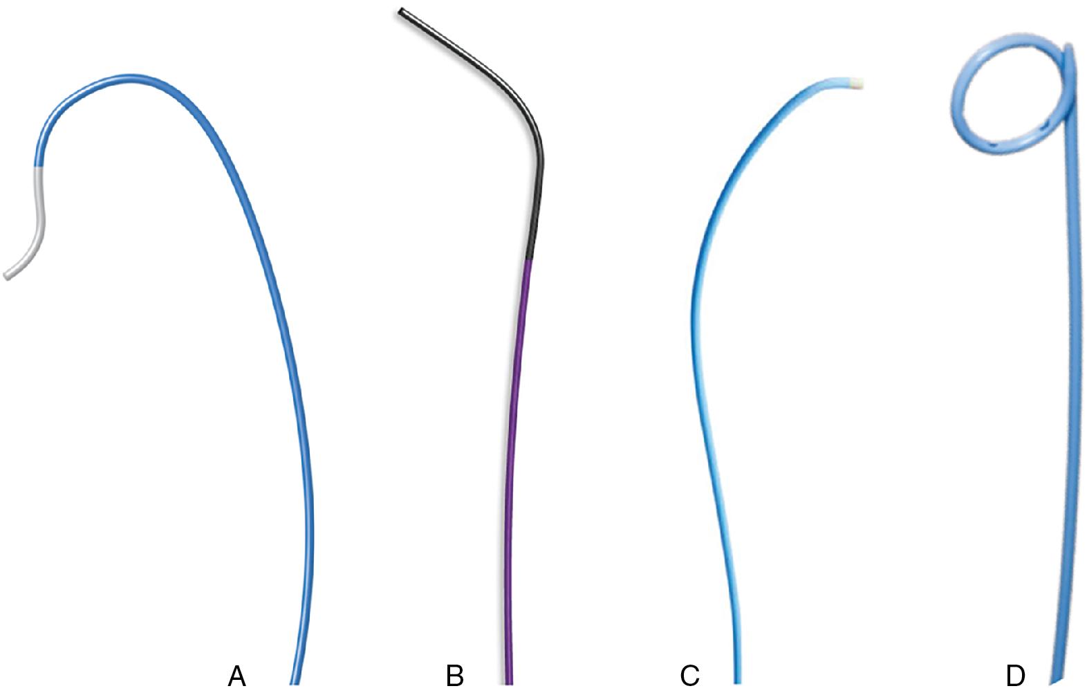
The distribution of the cusp calcifications should be assessed in order to locate where the valve opens. There are two techniques to successfully cross a stenotic aortic valve:
The anatomy-based technique is preferred. It allows optimal orientation of the catheter tip to direct the guidewire toward the aortic orifice. A step-by-step approach would be as follows:
Obtain the perpendicular implantation view with the aortic anatomy with all three cusps aligned in the same plane.
Point the AL-1 catheter toward the LCC.
Rotate the AL-1 clockwise as you move the straight wire in small steps toward the valve opening until it crosses the valve and into the LV ( Fig. 10.6 , ).
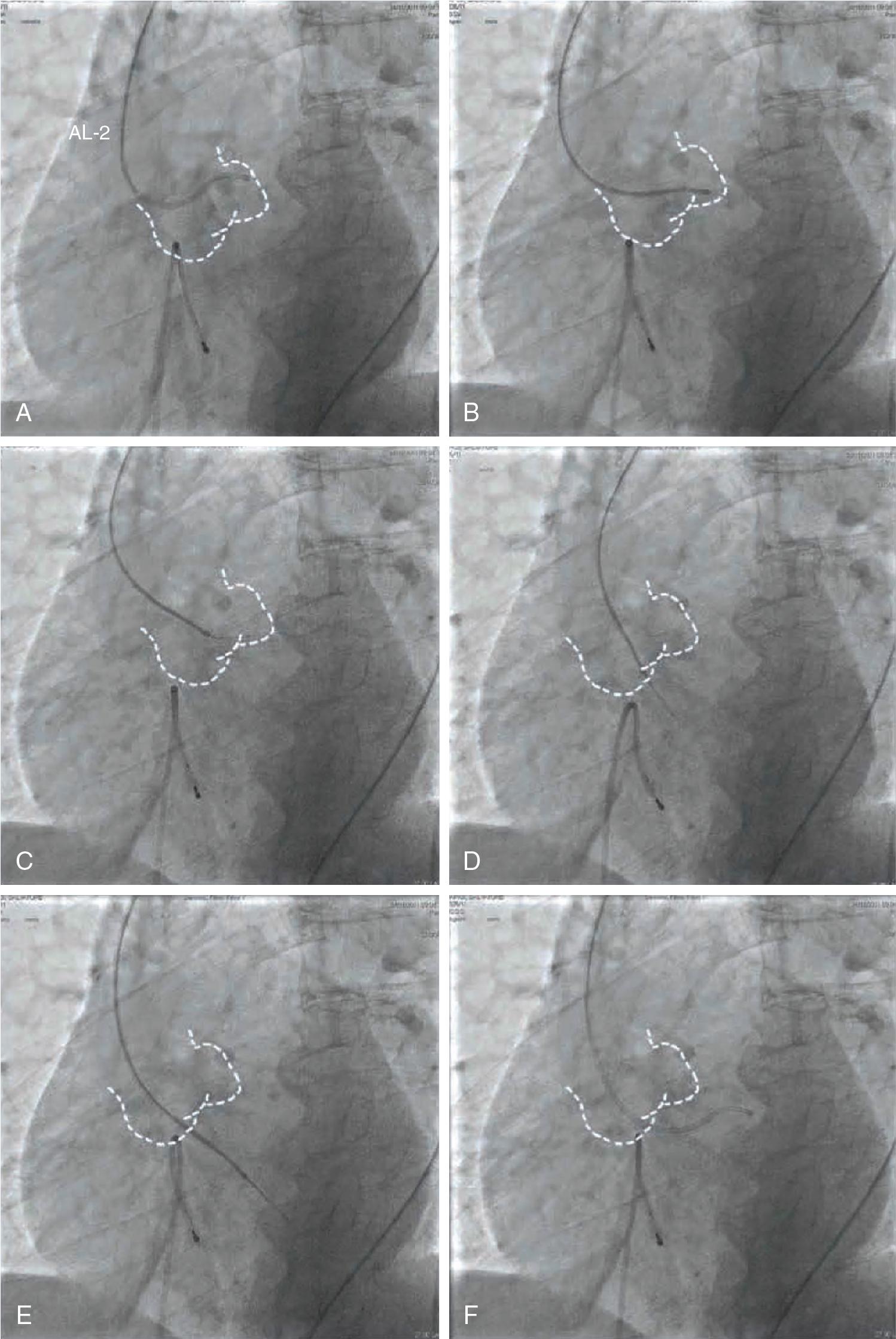
The second technique for crossing the aortic valve provides for positioning the catheter (AL, JR, or MP) at the level of the ascending aorta using a straight-tipped hydrophilic wire, which is gently advanced and pulled back in sequence until crossing of the aortic valve.
Once the AL catheter crosses through the aortic valve and enters the LV, an RAO view must be gained to follow the path of the catheter through the LV and to check for its optimal positioning, close to the apex of the ventricle, and to position the stiff guidewire.
The stiff guidewires used in TAVI are the preshaped Safari (Boston Scientific) or Confida (Medtronic); alternatively, the 1 cm smooth tip Amplatz Super Stiff (Boston Scientific), which must be manually curved on the soft distal part (1 or 3 cm), can be used. It is important to pay attention to preshaping: it is recommended to create a smooth transition at the apex, without sharp bends, fitting the LV contour ( Fig. 10.7 , ).
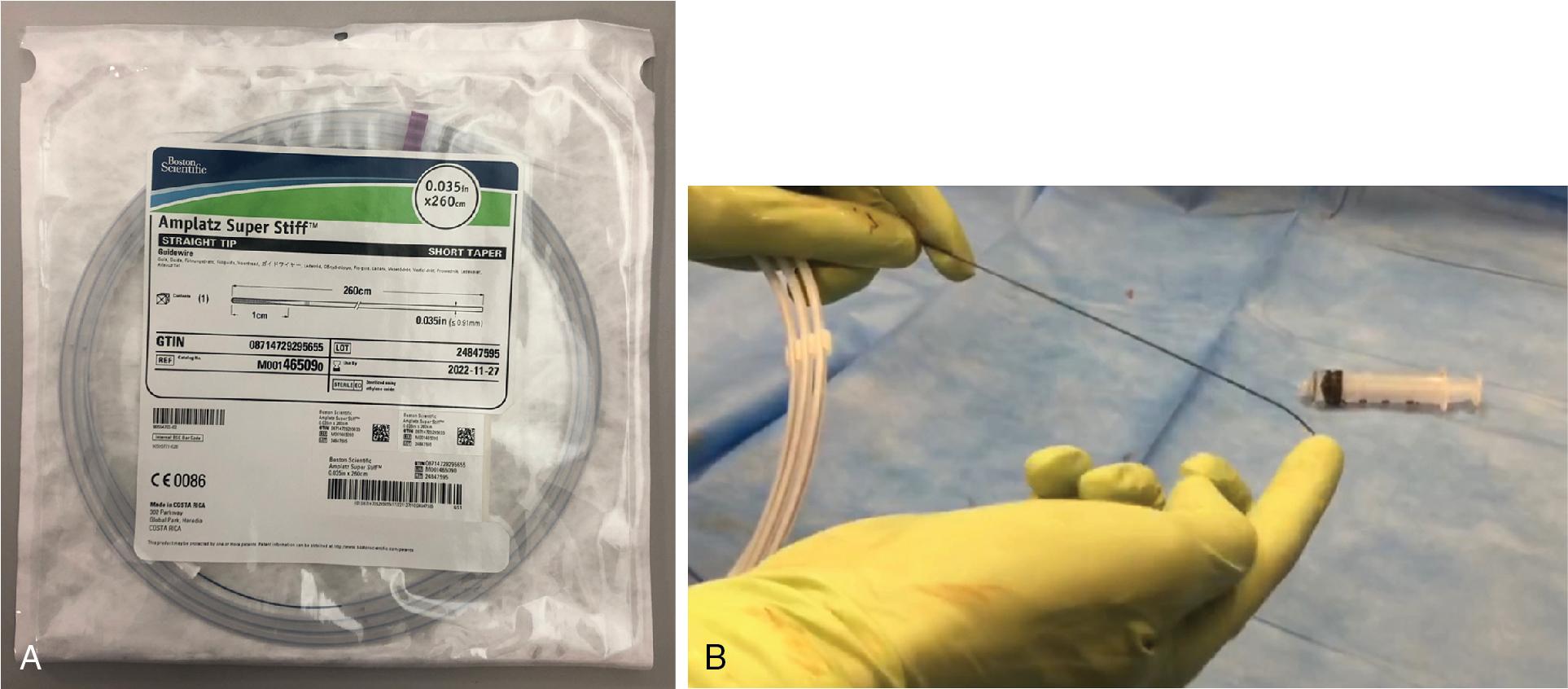
There are different techniques to successfully place the stiff guidewire into the LV.
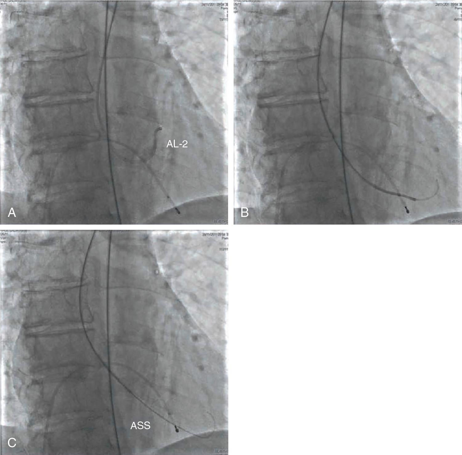
Standard procedure:
The AL catheter is advanced into the LV and the straight-tip guidewire is exchanged for an exchange-length J-tip guidewire.
The AL is exchanged for a pigtail catheter.
The stiff guidewire is advanced through the pigtail catheter and positioned in the apex of the LV.
The pigtail catheter is removed while maintaining guidewire position in the LV.
In expert hands:
The AL catheter is advanced into the LV.
The straight-tip guidewire is exchanged directly for the stiff guidewire and positioned in the apex of the LV ( Fig. 10.8 and Table 10.1 ).
| Complication | Cause |
|---|---|
| Ventricular arrhythmias | Mechanical stimulation by the catheter or the guidewire |
| Coronary artery dissection | Probing the valvular plane with the straight-tipped or hydrophilic guidewire |
| Cardiac perforation | Positioning of the guidewire in the LV |
| Cerebral embolization of calcium fragments | Probing the valvular plane with the straight-tipped or hydrophilic guidewire |
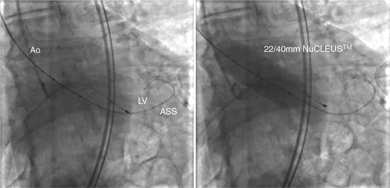
In 1986 Cribier et al. reported three elderly patients with calcific aortic stenosis (AS) who underwent successful percutaneous balloon aortic valvuloplasty (BAV), with a reduction in peak aortic systolic gradient, an increase in calculated aortic valve area, no significant increase in aortic regurgitation or embolic accidents, and striking clinical improvement. BAV results in an increased orifice dimension and leaflet mobility by virtue of fractures of nodular calcifications, presumed microfractures within the valve leaflets, or separation fused on commissures, alone or in combination ( Fig. 10.9 , ). The initial enthusiasm surrounding this technique, touted as an alternative to surgical aortic valve replacement (SAVR), waned with subsequent large registries, which showed a high midterm restenosis rate. For many years, this procedure has been used only as a palliative remedy for short-term symptom relief in elderly, nonsurgical patients with severe AS. BAV is safe in experienced hands and is a low-cost procedure that needs only a brief hospitalization.
Recently, the increasing rise of TAVI resurrected and rejuvenated the field of BAV. At present, BAV is not considered the standard of care for AS, but, as mentioned, is increasingly being used in patients affected with degenerative aortic valve disease who present with severe comorbidities and a severely impaired hemodynamic clinical status or as a bridge to SAVR or TAVI.
BAV can play an integral role to predilate the stenosed aortic valve for easier delivery of the TAV prosthesis, enhances prosthesis implantation, and enhances expansion within the calcified aortic valve annulus.
Lower profile delivery systems, new device designs, and increasing operator experience have enabled direct TAVI (without predeployment BAV). Recent studies have shown that postimplantation balloon dilation and moderate/severe paravalvular leak are not significantly different between a predeployment BAV and direct-TAVI approach, regardless of the TAVI device.
However, unfavorable features for direct-TAVI have been detected, such as large nodules and diffuse calcification of the aortic annulus, severe aortic valve calcification defined as leaflet thickness >5 mm, a bulky and asymmetric calcification distribution, valve area <0.4 cm 2 with irregular and/or eccentric orifice, and presence of calcification nodules at the left ventricle outflow tract or close to coronary ostia ( Table 10.2 ).
| Large nodules and diffuse calcification of the aortic annulus |
| Severe aortic valve calcification defined as leaflet thickness >5 mm |
| Bulky and asymmetric and calcification distribution |
| Aortic valve area <0.4 cm 2 |
| Irregular and/or eccentric aortic valve orifice |
| Presence of calcification nodules at the left ventricle outflow tract or close to coronary ostia |
In patients with low-flow–low-gradient AS, BAV can also have a prognostic/diagnostic role in assessing improvement in LV function after the reduction of the transaortic gradient.
In patients with pulmonary hypertension or severe functional mitral regurgitation, BAV has the potential of reducing the degree of pulmonary pressure and mitral regurgitation with the possibility of improving procedural and short-term outcomes.
Furthermore, BAV may play a role in the sizing of the annulus to choose the type and sizing of TAVs in patients without prior MDCT and to assess coronary artery flow before valve deployment in case of low coronary takeoff ( Fig. 10.10 , ).

Become a Clinical Tree membership for Full access and enjoy Unlimited articles
If you are a member. Log in here