Physical Address
304 North Cardinal St.
Dorchester Center, MA 02124

Specular microscopy displays light that is reflected in a “mirror-like” fashion off the tissue from the incident light.
Specular microscopy’s primary use is in the imaging of corneal endothelial cells, whereas confocal microscopy has replaced it for epithelial and stromal imaging. Endothelial cell density, mean cell area, polymegethism or coefficient of variation, and pleomorphism or percent hexagonality are useful measures.
Quantitative and morphologic analyses are helpful in identifying various disease states, preoperative planning, and eye banking.
Specular microscopy plays a significant role in safety and efficacy studies of anterior and even posterior segment procedures, devices, and pharmaceutical interventions.
Central reading centers for specular image analysis are important and recommended for US Food and Drug Administration multicenter clinical trials to obtain reliable, accurate, and reproducible results.
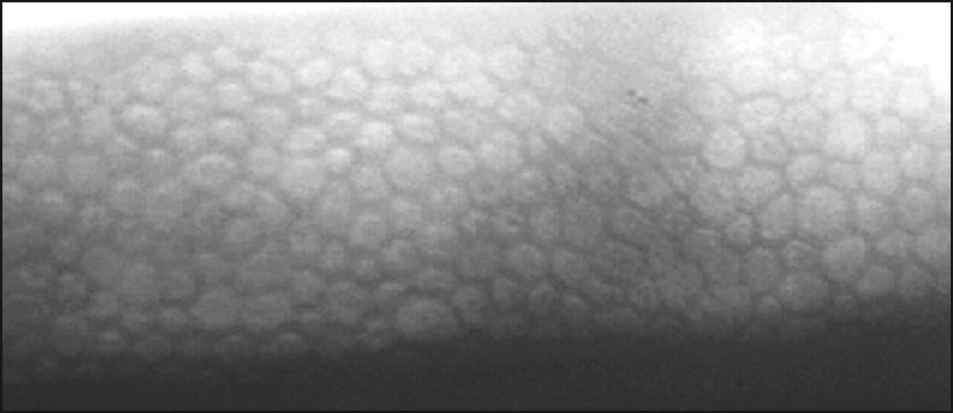
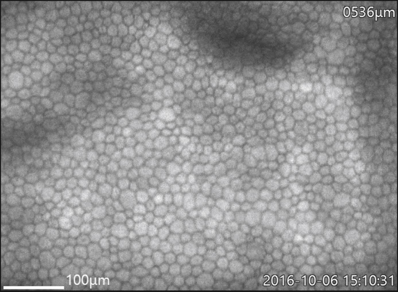
The specular microscope displays light reflected from an optical interface. The optical interface of greatest interest is that between the corneal endothelium and the aqueous humor. Although the corneal epithelium, stroma, and crystalline lens can also be viewed, imaging of these cellular structures has been largely supplanted by confocal microscopy and optical coherence tomography. Depending on the instrument used, the projected light can be in the form of a stationary slit, a moving slit, or a moving spot; the optical design can be either confocal or nonconfocal; and the interface can be contact or noncontact. The young normal corneal endothelium as seen by specular microscopy ( Fig. 13.1 ) shows a quasi-regular array of hexagonal cells of similar size. With aging, trauma, and corneal disease, this regularity is lost and corneal clarity can become diminished.
The first direct visualization of the normal endothelium was performed by Vogt in 1918 and of Fuchs endothelial corneal dystrophy by Graves in 1924. It was not until 1968 that Maurice described the first laboratory specular microscope that could be used to study excised living corneas. , Modifications of this specular microscope were made by Laing et al. and later by Bourne and Kaufman, allowing routine clinical examination and photography of the corneal endothelium.
Specular microscopes have evolved from wide-field and higher-resolution contact microscopes. , Narrower-field high-resolution noncontact microscopes have also been developed. These are equipped with software to obtain an automated or semiautomated determination of endothelial cell density (ECD) and morphology, including coefficient of variation (CV) and percentage of hexagonal cells (%HEX). Currently, specular microscopes are available for central and peripheral imaging for both clinical and eye bank use.
The optical principles of specular microscopy are well described in the corresponding chapter on this subject in the fourth edition of this textbook. Briefly, light striking a surface can be reflected, transmitted, or absorbed. Some combination of these three effects generally occurs. Of primary importance in clinical specular microscopy is the light that is reflected specularly (i.e., “mirror-like”), where the angle of reflection is equal to the angle of incidence. It is this light that is captured by the specular microscope and forms the image of interest. As light passes through the cornea, it encounters a series of interfaces between optically distinct regions. At each interface, some light is reflected back and some is transmitted deeper into the cornea. The greater the difference in index of refraction between the regions, the greater the intensity of reflected light. The more edematous the tissue, the more light is scattered. A portion of this reflected light is collected by the objective lens of the specular microscope and, at the film plane of the microscope, forms an image of that part of the cornea on which the instrument is focused ( Fig. 13.2 ). With wide-field scanning, slit, or scanning spot confocal microscopes, the slit or spot is made very small to minimize interference and increase image quality. Details on confocal microscopy imaging are provided in Chapter 14 of this edition.

Commercially available contact and noncontact specular microscopes are easy to use, with little if any patient discomfort. To obtain good patient cooperation and ultimately acquire high-quality images for analysis, it is important first to explain the procedure to the patient. The positioning of the head and establishment of patient comfort are key to minimizing movement and allowing the recording of optimal images of the endothelium.
In noncontact specular microscopy, instructing the patient to blink to wet the cornea and then to hold still just prior to image capture improves image sharpness. Also of note with noncontact instruments is that attempts to image a thickened cornea will sometimes fail in the automated capture mode and may require the operator to use a manual mode. If a contact specular microscope is being used, a topical anesthetic will be administered. Once the cornea is contacted, punctate epithelial erosions may be seen; however, these usually disappear within a few hours. Placing the eye in a straight-ahead position is best achieved with an internal fixation point. Optimal photographs are obtained when the cornea is relatively thin and clear, with minimal scarring or edema. Light reflexes from the iris can obscure the endothelial mosaic and are best eliminated by dilating the pupil.
A standard approach to examining the corneal endothelium is necessary for observing change over time. Noncontact specular microscopes use internal fixation points to provide a standardized approach to consistently image the central endothelium, midperiphery, and periphery. The central targets, though varying by instrument, image within the central 3-mm area. Peripheral imaging is considered either paracentral 3 mm from central or peripheral 4 mm or greater from central at minimum in the nasal temporal superior and inferior regions.
With these systems, the patient view is shifted when the technician selects the desired region. It is important to remind the patient to follow the fixation target. When a contact specular microscope is being used, the beam of light is directed through the pupil to ensure placement of the cone on the central portion of the cornea. Systematic scanning superiorly, inferiorly, nasally, and temporally will ensure a thorough evaluation of the endothelium.
To best evaluate small changes over time in any region, including the central endothelium, the technician should image the region three times at the same sitting and record the average of the three images’ analyses. It is also important for the technician to use the same image analysis method from baseline and throughout the follow-up period for longitudinal studies. Most specular microscopic studies of the corneal endothelium determine solely the ECD of the central endothelium in order to attempt to examine the same endothelial cell area consistently over time. However, this may be misleading and will not necessarily reflect the impact of a surgical procedure that principally damages the peripheral cornea near the wound where instrumentation was introduced (e.g., phacoemulsification). Changes in the central corneal endothelium in both ECD and morphology may take some time (months or years) to be reflected. The paracentral and peripheral endothelium, in particular superiorly, has higher ECD than the central endothelium and may assist in maintaining central ECD and function. Serial central and regional imaging should be performed when an intervention affects the peripheral region, initially to determine the peripheral reserve and on subsequent visits to track (e.g., cataract surgery in the Fuchs dystrophy patient). Conversely, procedures affecting the central region where peripheral reserve is essential has focused even greater interest on peripheral imaging (e.g., the Descemet stripping only [DSO] procedure).
There are several specular microscopes commercially available, both noncontact and contact ( Table 13.1 ). Most instruments have computer integration and semi- or fully automated analyses. Some instruments allow manual analysis and/or adjustments to the automated analyses. The noncontact instruments use autotracking and focusing technology. A widely used clinical instrument in the United States is the Konan CellChek SL (Konan Medical USA, Irvine, CA). Using this instrument, tracking of the cornea and imaging of the endothelium are automated, requiring minimal intervention by the operator. Once the patient is aligned, the operator presses a button to start the imaging process. The optics of the instrument first objectively align relative to the cornea by using the Purkinje images until the proper specular reflection mode is achieved. The instrument then objectively focuses back to the endothelial surface, the flash lamp is triggered, and the resulting endothelial photograph is displayed on the monitor. In addition, verification of the actual location of the image is captured and can be displayed on an external eye image. Other noncontact instruments provide sequential images (Tomey, Inc., Phoenix, AZ, and Nidek, Fremont, CA) or a live view (HAI Labs, Inc., Lexington, MA), all automatically selecting the best images.
| Manufacturer | Type | Model | Analysis Options | Advertised Features | Sample Image |
|---|---|---|---|---|---|
| HAI Labs, Inc. Lexington, MA |
Clinical, contact | CL-1000xyz | Automated Variable frame Corners |
FOV 250 × 400 μm Focal depth 0-999 μm Pachymeter Live sequence capture HAICAS/CL Cell Analysis System Image enhancement functions Cell density, polymegathism, pleomorphism Statistical, histogram, and correlation analysis, cell by cell detail Unlimited calibration groups and databases for studies |
|
| HAI Labs, Inc. Lexington, MA |
Clinical, noncontact | CL-1000eva | Automated | FOV 300 µm × 600 µm Attaches to compatible slit lamp Live view of corneal endothelium Manual tracking for high level of control Automatic image capture Auto selection of good endothelial images Manual selection of region of interest for automated analysis Analysis includes up to 200 cells Cell density, polymegathism, pleomorphism, corneal thickness |
|
| HAI Labs, Inc. Lexington, MA |
Eye bank; viewing chamber only EB-2000xyz; both viewing chamber and vials EB-3000xyz | EB-2000xyz, EB-3000xyz | Automated Variable frame Corners |
FOV 450 µm × 500 µm Digital pachymeter Custom vial holder HAICAS/EB Cell Analysis System Pixel-based calibration validation 640 × 480 full resolution bmp images Cell density, polymegathism, pleomorphism Statistical, histogram, and correlation analysis, cell by cell detail EBAA-compliant reports |
|
| Konan Medical USA, Inc. Irvine, CA |
Clinical, noncontact | CellChek SL | Automated Semiautomated Center Center-flex Corner method |
FOV 240 × 400 μm Fully automated alignment and focus, easy to use Five fixation points and verification of actual location of endothelial image on corneal photograph Optical pachymetry at all five fixation points integrated computer system and analysis software |
|
| Konan Medical USA, Inc. Irvine, CA |
Clinical, contact | CellChek C ∗ | Autotrace Semiautomated Center Center-Flex method |
FOV 650 × 480 μm wide-field scanning specular microscope Full corneal layers visualization: Epithelium surface, stroma, nerves, endothelium. Floating mechanism maintains focus distance. Location can be moved to image limbus to limbus Video imaging system |
|
| Konan Medical USA, Inc. Irvine, CA |
Eye bank; viewing chamber and vial | CellChek D; CellChek D+ | Endothelium Center, center-Flex corner methods Whole cornea Diameter Circumference, area, line. |
FOV 1000 × 750 μm Specular and enhanced donor tissue imaging Imaging of damaged or dead cells Imaging of interface of precut tissues Endothelial assessment Enhanced imaging of epithelium Imaging of debris/red blood cells Low magnification field to observe entire cornea (Finder Mode) Built-in pachymeter Built-in thermometer |
|
| Nidek Frement, CA |
Clinical noncontact | CEM-530 | Automated; progression analysis | FOV 250 × 550 μm Auto-tracking and auto shot 15 fixation points Central, paracentral (8 at 5 degrees visual angle) and peripheral (6 points at 27 degrees visual angle) 16 images captured and sorted by quality Optical pachymetry Networkable without external computer |
|
| Tomey, Inc. Phoenix, AZ |
Clinical noncontact | EM-4000 | Core method | FOV 250 × 540 μm Auto alignment/manual alignment Continuous autocapture of 16 images. Auto/manual selection One central and 12 peripheral points Database function |
|
| Topcon Medical, Inc. Tokyo, Japan |
Clinical noncontact | SP-1P | Automated; manual adjustment | FOV 250 × 550 μm Two photography modes—sequence and freestyle Automatic alignment and centering One central and 16 peripheral fixation targets Single and panorama automated analyses—Integrated color monitor and data analyses |
Single image 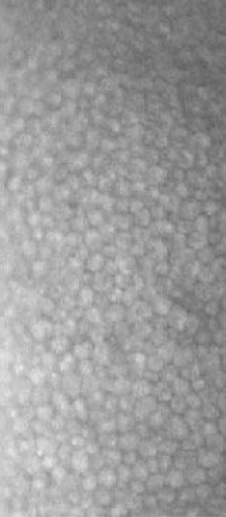
|
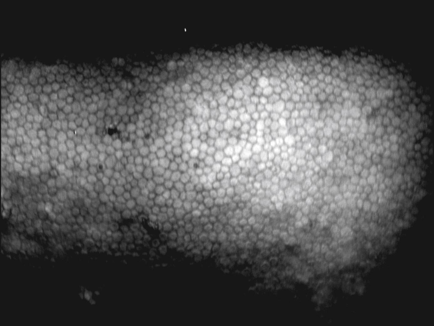
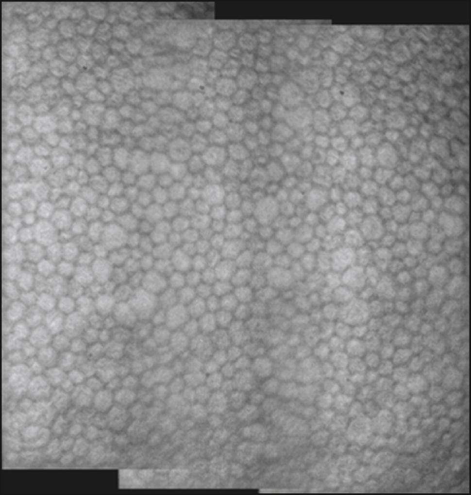
HAI Laboratories, (HAI Laboratories, Lexington, MA) offers a contact specular microscope with a focal depth of 0–999 μm. Though less comfortable for the patient because it is a contact instrument, it obtains sharp wide-field images regardless of corneal thickness or disease. An interesting feature of the Topcon SP-1P (Topcon Medical Inc., Tokyo, Japan) is the merging of multiple central and paracentral images to create a panorama allowing a larger nonoverlapping area of the cornea to be analyzed. A detailed progression analysis is a feature of the Nidek CEM-530 ( Fig. 13.3 ).

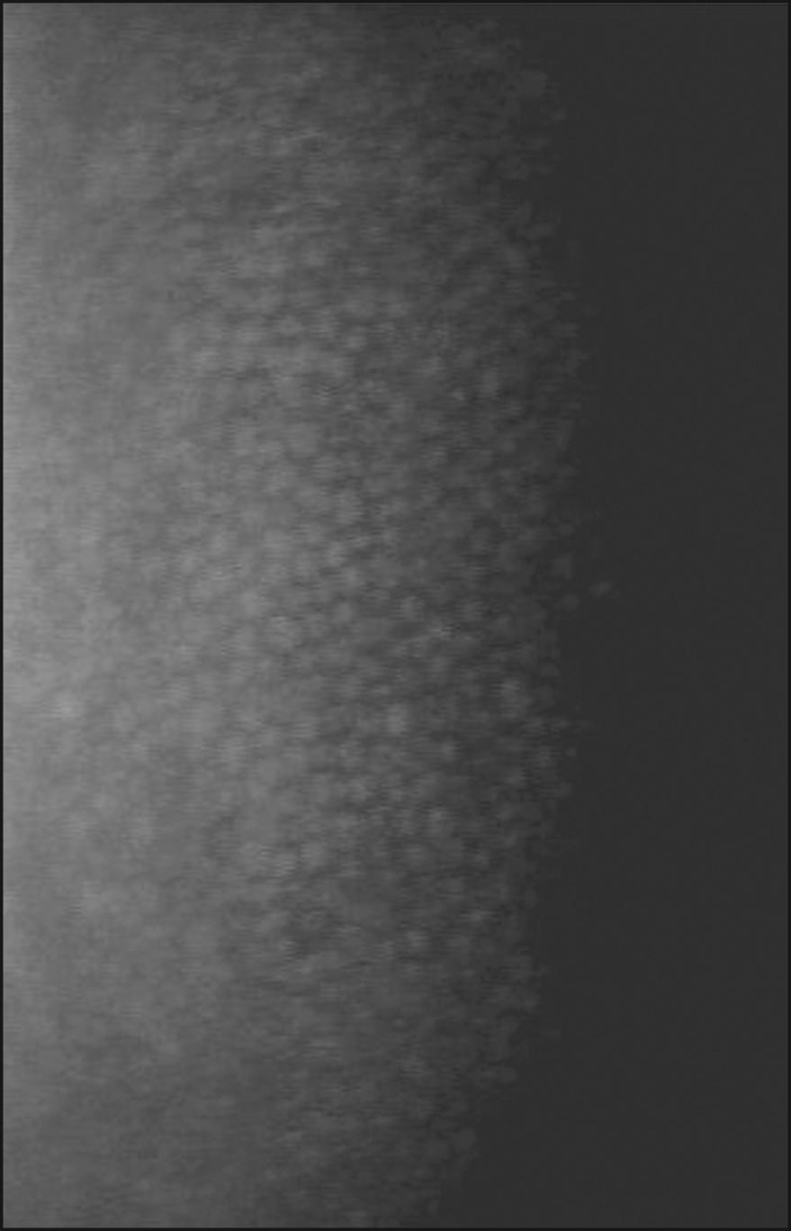
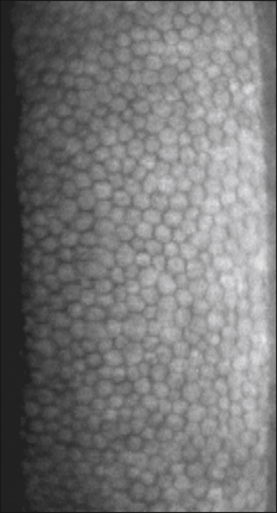
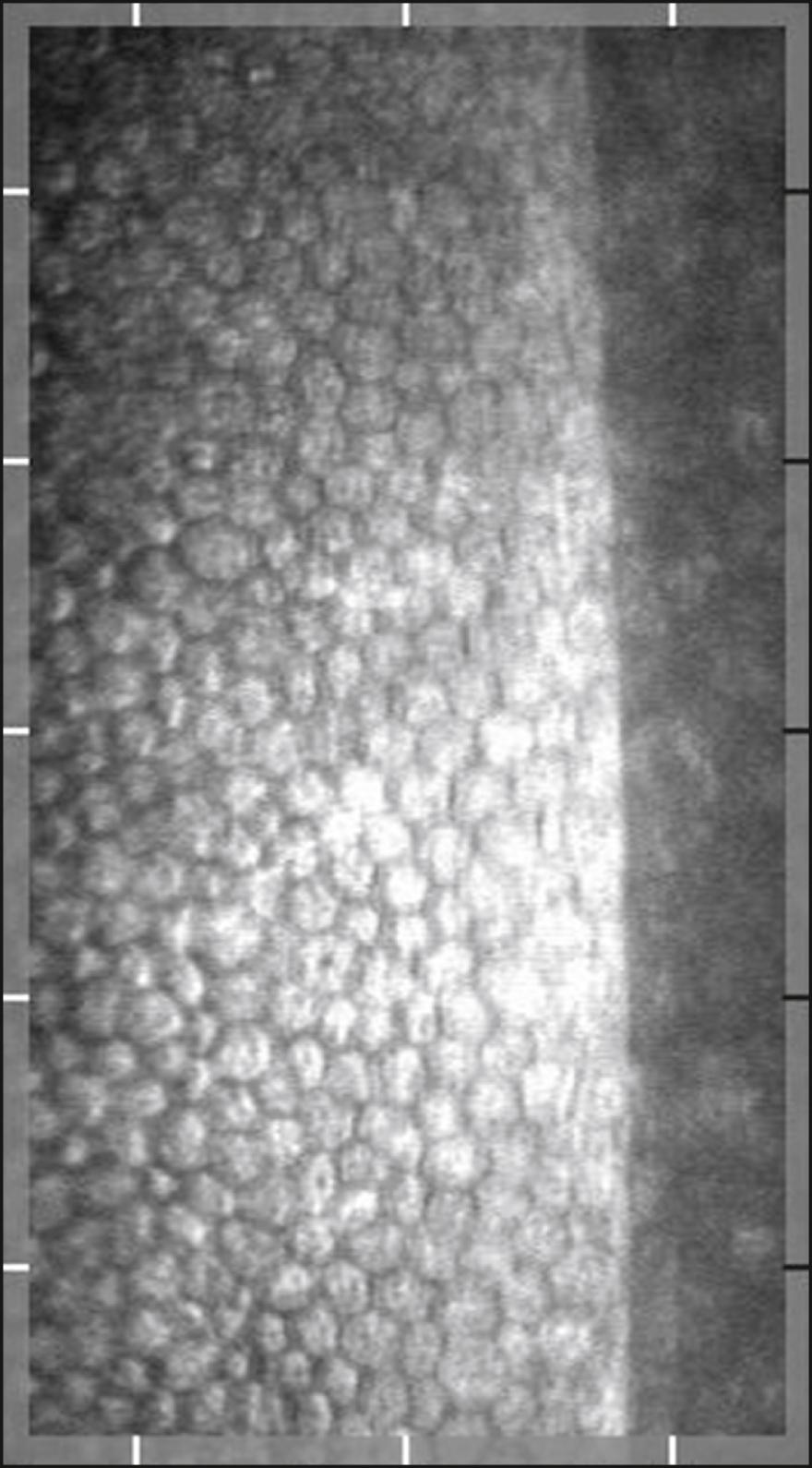
Konan’s CellChek C, not yet cleared by the US Food and Drug Administration (FDA) for sale in the United States, is a unique wide-field scanning specular microscope. Using slit scanning technology, it allows for still image and video visualization of the corneal layers ( Fig. 13.4 ).

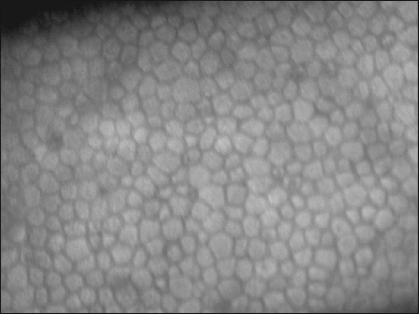
Corneal epithelial cells do not normally present a flat surface suitable for specular microscopy. If a contact lens is pressed against the anterior surface of the eye, however, the epithelial cells can be flattened and can reflect light in a mirror-like fashion. The normal corneal epithelium contains polygonal cells of varying brightness ( Fig. 13.5 ). Most cells can be placed into one of three groups: dark, medium, and light. Hexagonal, pentagonal, and triangular cells may be present, but rounded, enlarged, or elongated cells are considered abnormal. The chapter on specular microscopy in the previous edition of this textbook highlighted the numerous clinical applications of specular microscopy in imaging the epithelium. However, most of these applications are from publications that appeared more than 20 years ago, thus emphasizing the limited application of epithelial specular microscopy. Confocal and optical coherence tomography have largely replaced specular microscopy for visualization of the epithelium, providing new insights into its appearance and portraying changes in the basal epithelium, wing cells, and superficial cells in both normal and disease states, particularly dry eye.

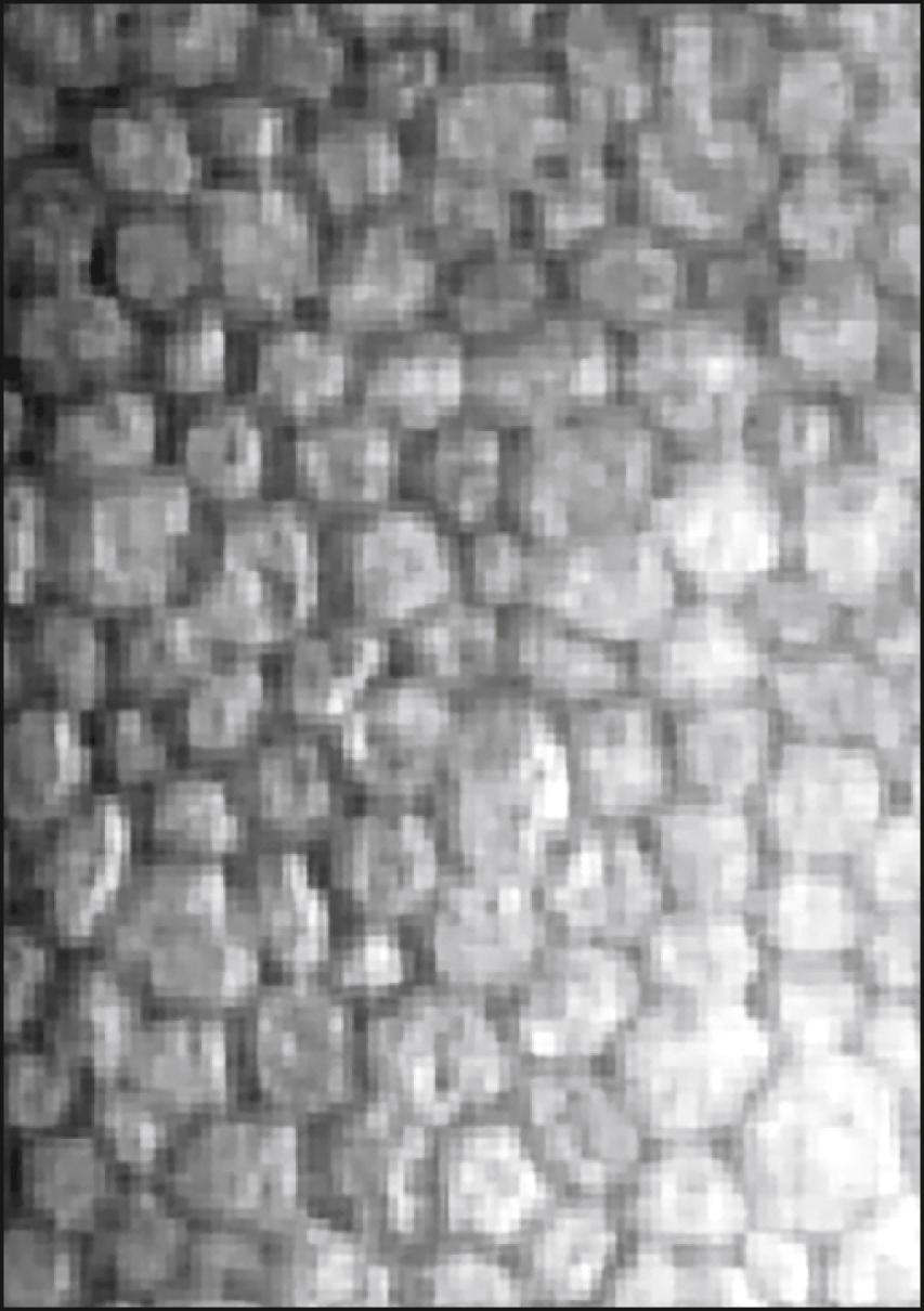
A number of abnormal endothelial structures can be seen with specular microscopy. One of the most notable is corneal guttae ( Fig. 13.6A ). Guttae are excrescences of the Descemet membrane. They can be seen with the specular microscope much earlier than by slit lamp biomicroscopy. They begin as small dark structures; however, in time these structures enlarge, often becoming larger than individual endothelial cells. Guttae can be dome shaped, or they can assume the shape of a mushroom. If an excrescence assumes a mushroom shape with a flat top, light can be specularly reflected from its surface, which acts much like a mirror. When this occurs, a bright spot can be seen within the dark structure. In the case of Fuchs dystrophy, the surrounding endothelial cells are often abnormally shaped. Guttae, however, can also be seen in the far periphery of normal young individuals. In this case, they are called Hassall-Henle warts. The excrescence is usually shaped more like a dome than a mushroom, and the surrounding endothelium does not look abnormal.
 Isolated smooth excrescences (corneal guttae). ( B ) Multiple coalesced excrescences. Only the bright reflection from the apex of each excrescence is clearly seen. ( C and D ) Intracellular bright structures possibly representing cell nuclei. ( E ) Pigmented endothelial deposits. ( F ) Dark structures possibly representing endothelial cilia. ( G ) Intracellular dark structures possibly representing intracellular vacuoles. ( H ) Intercellular dark structures believed to be invading inflammatory cells.")
Intracellular bright structures can sometimes be seen (see Fig. 13.6C and D ). They seem to be associated with stressed cells such as those seen after corneal transplantation. The size of the bright structure often corresponds to the size of the endothelial cell (the larger the cell, the larger the bright structure). This structure is felt to represent the cell nucleus. Some bright structures span several endothelial cells and have sharp borders, indicating that they are likely very near the endothelial-stromal interface (see Fig. 13.6E ). These structures are believed to represent pigment deposits on the endothelial surface.
Various dark structures can also be seen in specular micrographs. One such structure appears to be intracellular; it is small and has sharp borders. This structure is thought to represent endothelial cilia (see Fig. 13.6F ). Another intracellular dark structure is much larger and less distinct, suggesting that it is located within the cell (see Fig. 13.6G ). These are thought to represent intracellular vacuoles or blebs. Specular microscopy of patients with anterior uveitis has revealed well-demarcated dark structures usually located at endothelial cell intersections (see Fig. 13.6H ). These structures are uniform in size and are thought to represent invading white blood cells.
Become a Clinical Tree membership for Full access and enjoy Unlimited articles
If you are a member. Log in here