Physical Address
304 North Cardinal St.
Dorchester Center, MA 02124
Isolation of the layer or entity to be viewed is the key to slit lamp biomicroscopy.
Techniques of biomicroscopic examination include diffuse illumination, broad beam illumination, optical section, indirect illumination, red reflex illumination, specular reflection, and sclerotic scatter.
Slit lamp photography employs the same modes of illumination with modifications (such as the fill light) necessary for accurate photographic documentation.
“On August 3, 1911, Alvar Gullstrand presented his first rudimentary model of the slit lamp … and explained its optics and applications.” An occasion of tremendous significance to ophthalmology had taken place: Gullstrand had introduced a device with the potential to advance the understanding of the eye and its problems as profoundly as did the direct ophthalmoscope 50 years earlier.
This chapter deals primarily with techniques of examination (all applicable to the photographic process as well). In Section II , “Photography,” it addresses special considerations required for photodocumentation.
“The examination of the eyes is begun after establishing the history of the case. In making this examination, too much stress can not be laid upon the necessity of proceeding systematically, since otherwise important matters can very readily be overlooked. We first examine the patient with regard to his general physical condition as well as with regard to the expression of his countenance, and then, in observing the eyes themselves, proceed gradually from the superficial parts—lids, conjunctiva, and cornea—to the deeper portions.”
The ideal examination includes a careful, highly dynamic analysis of all structures, using each applicable form of illumination. The result should be a fully detailed, three-dimensional mental image of the segments of the eye. Although many abnormalities are easily identified, some of subtle expressivity cannot be ruled out without having exercised fully the capabilities of the slit lamp. In the absence of clear clinical signs, with only vague symptomatology reported, the examiner must exhaust all possibilities. After the abnormality has been identified, additional information about its severity, extent, or particular characteristics can be gleaned through observation under all forms of illumination.
The importance of a dynamic approach cannot be sufficiently stressed. Observing the eye in static light deprives the examiner of much of the available information. The process of examining the cornea in direct and indirect retroillumination from the iris, for instance, requires a scan of the cornea from one limbus to the other. This motion itself will reveal information that might otherwise go unnoted. It enhances the dimensional qualities of the information observed and results in a more accurate and complete impression of the extent and severity of the abnormality present. Similarly, observing the motion of the eye and the eyelids can provide important clues to normal or abnormal function.
Establishing a routine protocol will minimize the time required to complete an examination and provides a fail-safe measure to ensure its completeness. As the examiner gathers experience, an individualized routine emerges. Type of practice and attendant patient population may be influencing factors in establishing a protocol. When circumstances permit, steps of an examination that may cause somewhat greater discomfort (e.g., eversion of the upper eyelid, application of vital dyes) may best be carried out toward the end of the routine to help ensure the patient’s ability to cooperate throughout the examination.
The principle underlying the slit lamp biomicroscope is isolation of the layer or object to be viewed. This instrument provides precise and modifiable illumination plus magnification with which to isolate, and thereby make visible, fine detail ( Fig. 7.1 ). Composed of two primary components, the biomicroscope and the slit illuminator, the modern slit lamp is both highly efficient and accommodating. The addition of available accessories provides for an impressive array of functions.
Most biomicroscopes consist of a parallel Galilean telescope design. Utilizing optical changers, interchangeable oculars, or both, these instruments produce an effective range of magnification with excellent resolution. Many offer optional beam splitters to accommodate one-to-one teaching or to accept a digital camera for real-time display or recording for later use ( Fig. 7.2 ).
The slit beam delivery system is basically a projector, with the slit aperture as the actual “object” focused on a plane corresponding to the focal length of the biomicroscope. The foremost prowess of the slit lamp is its ability to create a focused, well-delineated, narrow slit beam that forms an optical section in transparent and translucent tissue. Because it is not restricted to a single configuration, however, this beam is highly malleable through the use of simple controls that dictate its size and shape. It finds many additional applications in its various forms.
The biomicroscope and illuminator are mounted on a common axis in a copivotal arrangement. This facilitates the parfocal (biomicroscope and slit beam are focused on the same plane) and isocentric (the slit beam is centered in the field of view) relationships essential for practical function. A departure from these relationships can be purposely created for certain techniques of examination; otherwise, the absence of isocentricity or parfocality indicates a faulty condition requiring adjustment or repair.
Although there are only a few basic forms of illumination, most have variable uses and are highly effective in specific applications. This chapter concentrates on those forms of illumination and techniques of examination and photography that specifically address the eyelids, conjunctiva, cornea, sclera, and iris. Other structures are mentioned as their examination may be helpful in establishing a diagnosis of conditions involving the principal structure under consideration.
Techniques of illumination are broadly divided into direct and indirect forms. Direct illumination, as the term implies, describes any situation where the beam of light is directed to strike the principal subject area. Direct illumination may be diffused or focal. Indirect illumination techniques use a secondary surface that reflects light onto the principal subject area or light transmitted through tissue from an area of adjacent illumination.
Diffuse illumination facilitates simultaneous observation of large areas at low magnification. The area surrounding the eyes, the eyelids, conjunctiva, sclera, cornea, and iris can be quickly reviewed for gross abnormalities. Initiating the slit lamp examination in this manner generates an early, overall impression and provides a unifying matrix for the more isolating magnifications and forms of illumination to follow. With the slit illuminator set at its largest aperture and the diffuser in place, the illuminator is rotated through its arc of travel from side to side. The effect is to create alternating axial and tangential illumination. Tangentially applied light, even when diffused, produces highlights and shadows and enhances the visibility of many changes. As shadows and highlights wax and wane with the oscillating illumination, alterations from normal topography become exaggerated and more readily apparent. A subtle presentation of molluscum contagiosum, for example, possibly hidden by cilia, may elude detection in static light but may become quite obvious through the motion of the illuminator and the biomicroscope. Abnormalities of the lashes—such as collarettes, scales, and broken or missing lashes—are well enhanced with this approach. Because of shadows cast by cilia and foreign matter and the generally translucent nature of such deposits, static light may not provide adequate discrimination. The dynamic travel of light, however, animates shadows and cascades highlights to fully dimensionalize and identify even mild expressions of various conditions ( Fig. 7.3 ).
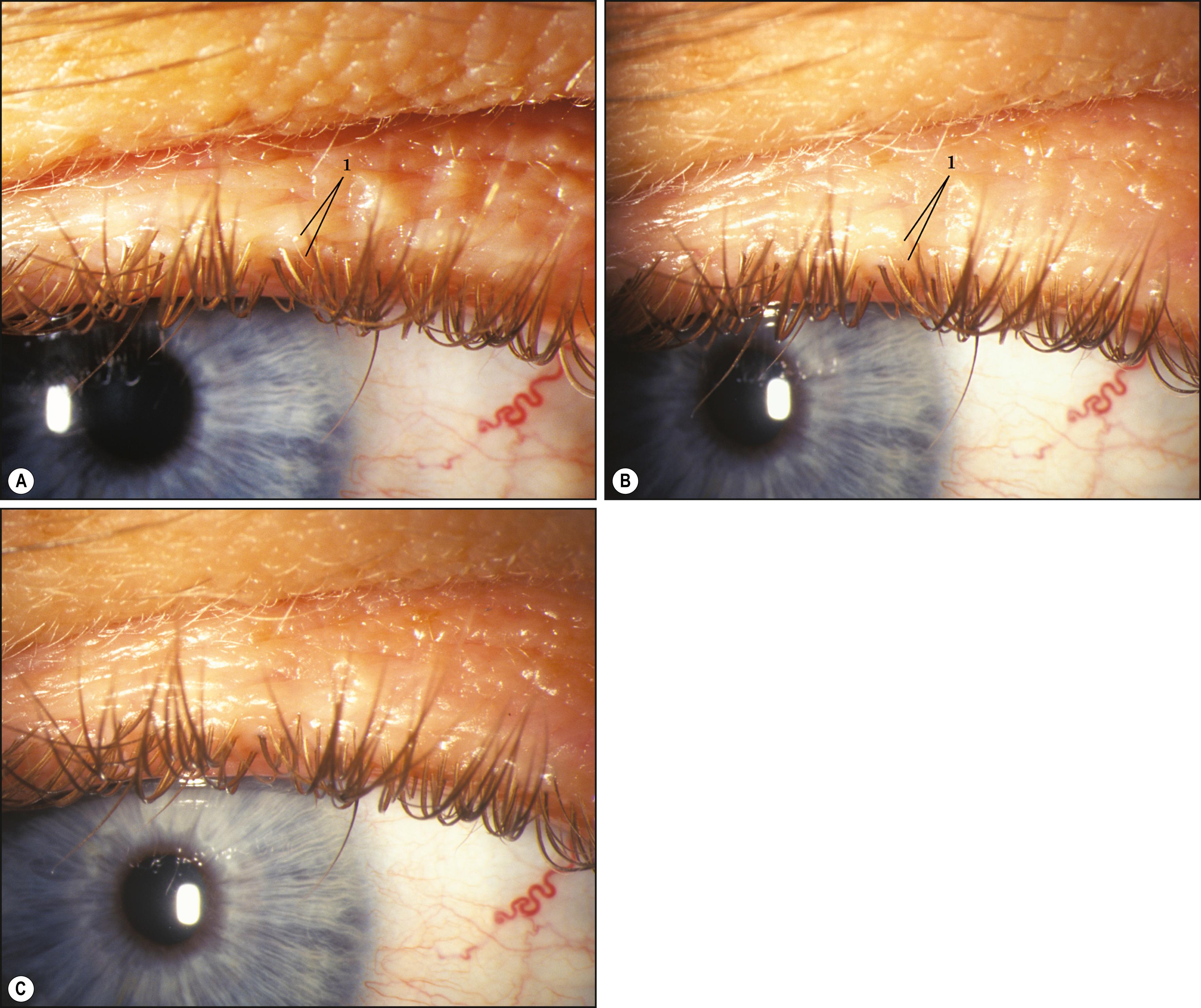
Focal alterations in skin color (e.g., hyperemia, hyperpigmentation, or hypopigmentation) also present more readily under diffused and dynamically altered light. Focal illumination tends to isolate an area with a proportionate loss of perspective. Additionally, the brightness of focal illumination, with its inherent contrast, makes slight differences in color difficult to appreciate. Another factor limiting the usefulness of focal illumination in this application is the possibly enhanced reflectivity of the skin of the eyelids. Secretions from resident sebaceous glands can engender considerable specular reflections, greatly limiting a view beyond the episurface.
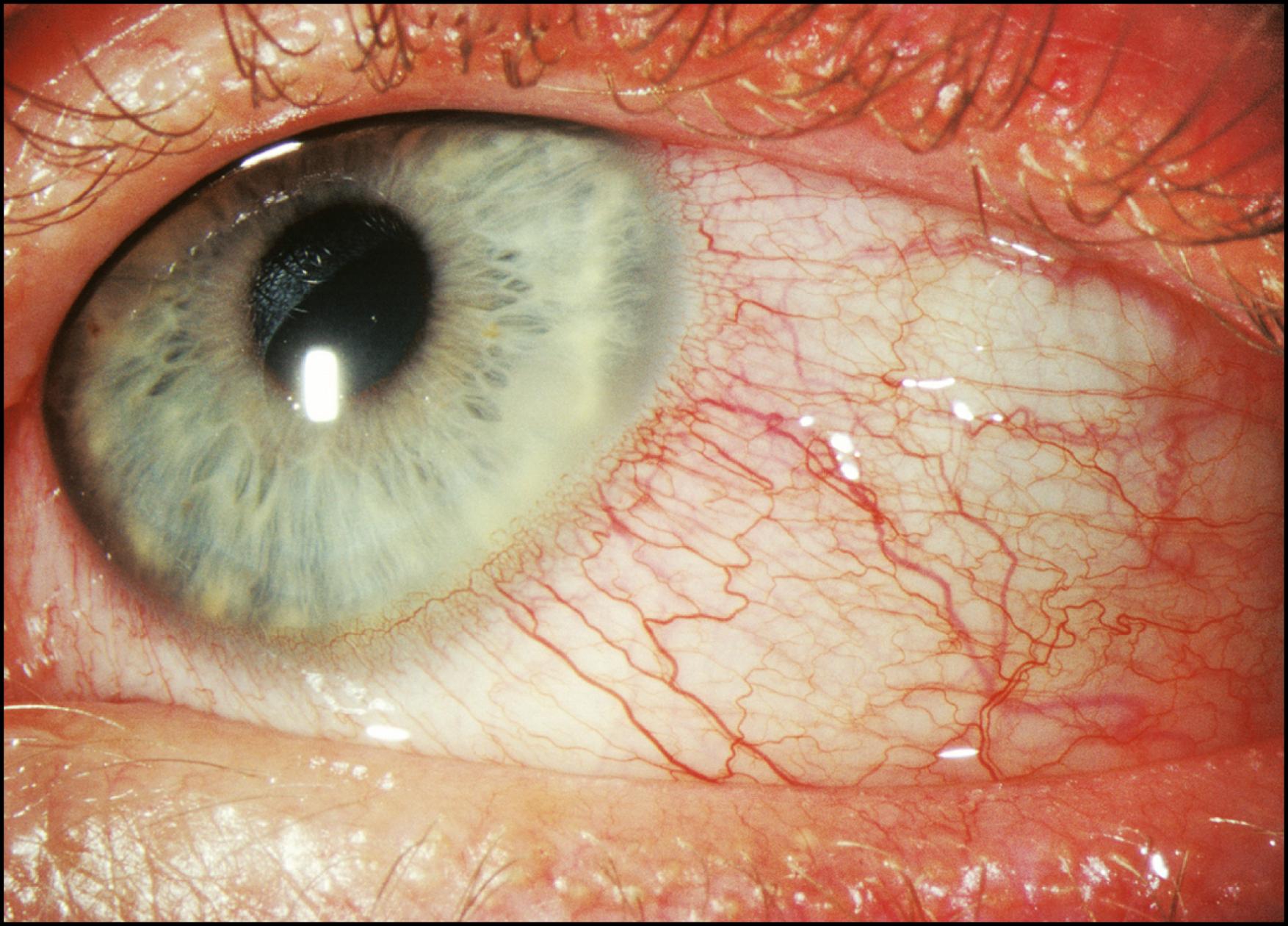
As stated earlier, the initial survey of the conjunctiva, sclera, cornea, and iris in diffuse illumination provides a useful introduction to the overall condition ( Fig. 7.4 ). Many abnormalities are easily visualized with this technique ( Box 7.1 ). Findings such as conjunctival injection, follicles, papillae, chemosis, membranes/pseudomembranes, and scarring are recognizable in diffused light and should prompt examination with additional forms of illumination. The inferior and superior palpebral conjunctivae and much of the fornices can be given a preliminary review in the same manner. Tangentially applied diffuse illumination with increased magnification is an excellent technique for initial examination of these surfaces ( Fig. 7.5 ).
Sclerocornea
Band keratopathy
Trichiasis
Distichiasis
Pinguecula
Papillae
Hordeolum
Entropion
Megalocornea
Lagophthalmos
Poliosis
Pterygium
Follicles
Hypopion
Ectropion
Corneal pannus
Blepharitis
Arcus senilis
Xanthelasma
Chalazion
Hyphema
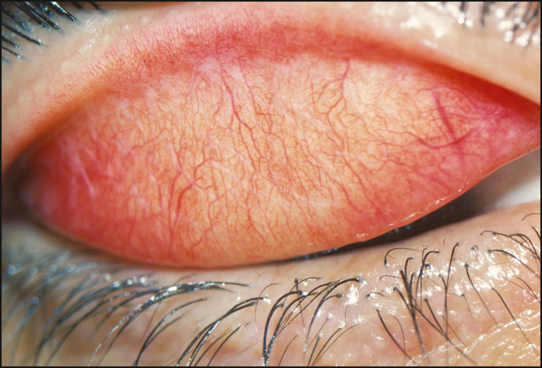
Inspection in diffuse light often provides the first indication of abnormalities present in the cornea. Gross opacification or changes that affect its topography present with little coaxing. After such an overview, further investigation can continue with more selective illumination and magnification.
The term broad-beam illumination is variably used and highly subject to interpretation. It can vary from a beam width of 1 mm to its full size of approximately 11 mm. In this discussion a flexible width is assumed. As with the recommended oscillation of the slit illuminator, a dynamically altered beam width is also beneficial. In this application, the beam is intended only as a source of bright focal illumination, with the width adjusted to maximize information within the area under study. As the light strikes tissue interfaces, it is reflected, refracted, transmitted, scattered, and absorbed in a highly variable fashion. Thus a given width of beam with its corresponding overall intensity may provide good information to confirm a particular entity but may overpower findings associated with another. A beam width of 2–3 mm can provide a good starting point ( Fig. 7.6 ). Although width is an important factor in the beam’s efficiency in specific applications, its intensity also affects its usefulness. A beam that is too bright will produce scatter, reducing the examiner’s ability to discriminate. Conversely, a beam intensity that is too “gentle” (in deference to the patient’s comfort, for example) may preclude detection of mild departures from the normal.
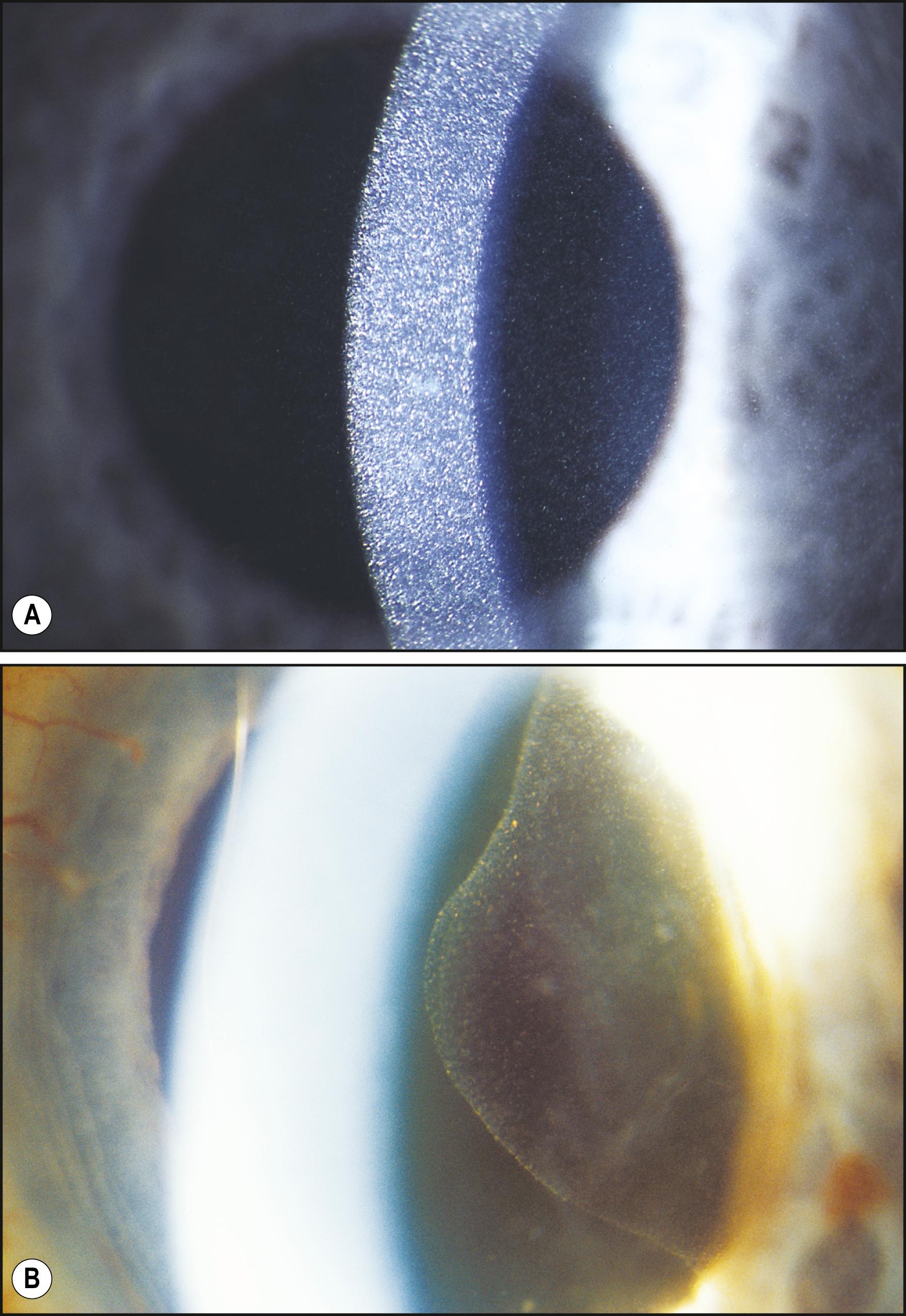
As various tissues are examined, suspected alterations from the normal will either be confirmed or will prompt the examiner to use more or less light in their continued pursuit. As a general rule, forms of illumination should be exaggerated in both directions beyond the ideal setting, especially with the use of broad-beam illumination. The beam should be narrowed to the point of diminished width and then increased in width beyond the ideal setting to the point at which information loss occurs once again. Only by testing these limits will optimum size and intensity become apparent.
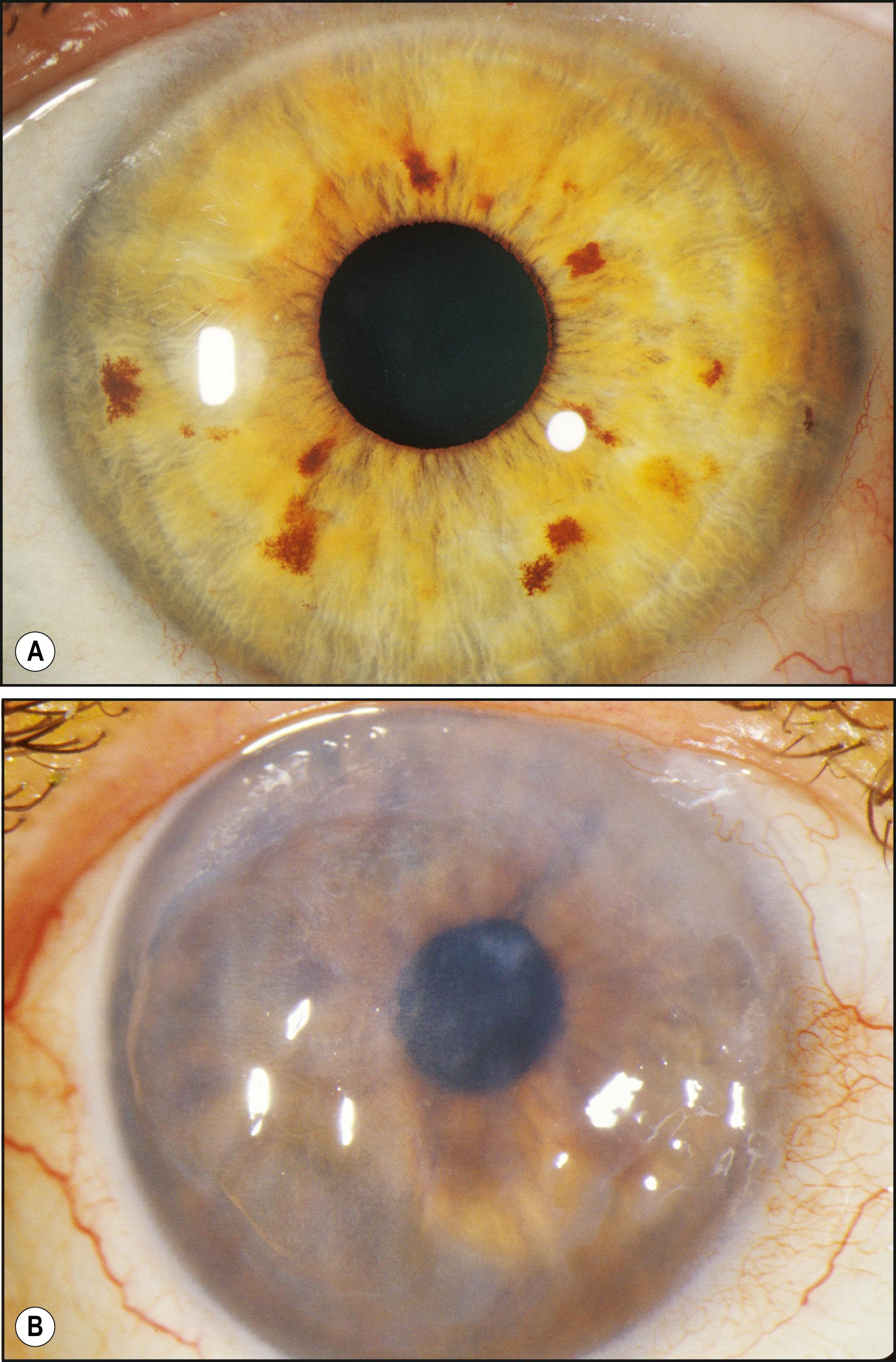
Many conditions are seen best using broad-beam illumination ( Box 7.2 ). All changes that are fairly opaque and reflect or absorb considerable amounts of light can be visualized easily. The light should be applied tangentially for maximum effectiveness. Topographic changes will become dramatically sculpted by the raking light. Additionally, oblique illumination will obviate the dazzling specular reflections resulting from axial lighting ( Fig. 7.7 ). Tangentially applied broad-beam illumination is one of the most effective forms for examining the iris surface ( Figs. 7.8–7.10 ) and certain changes within the lens ( Fig. 7.11 ).
Corneal vascularization
Basement membrane dystrophy
Reis-Bücklers dystrophy
Schnyder crystalline dystrophy
Terrien marginal dystrophy
Corneal cystinosis
Amiodarone vortex dystrophy
Prominent corneal nerves
Salzmann nodular degeneration
Posterior embryotoxon
Corneal scars
Lisch nodules
Keratic precipitates
Granular dystrophy
Iris atrophy
Pterygium
Band keratopathy
Macular dystrophy
Arcus senilis
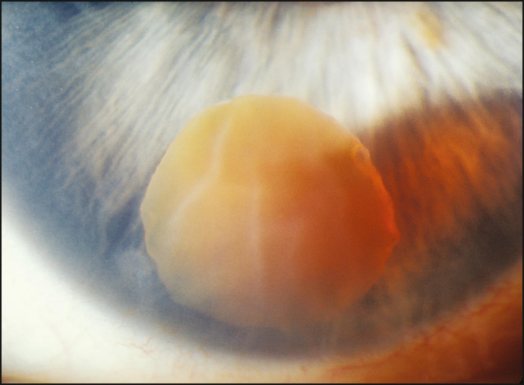
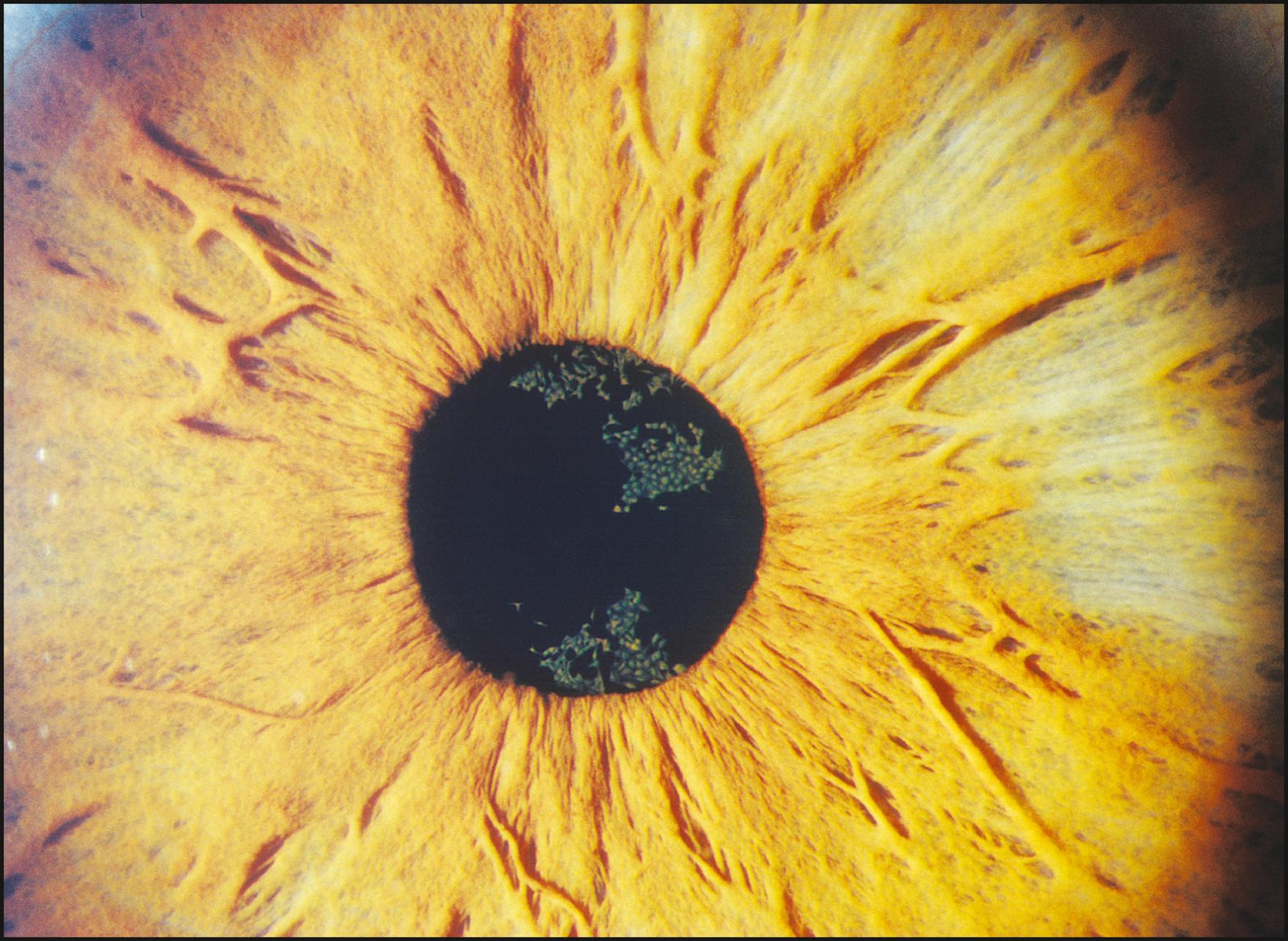
When no abnormalities are seen with this technique, more selective forms of illumination are indicated. The absence of findings under broad-beam illumination should never encourage the conclusion that abnormalities are not present. However useful in the applications described earlier, broad-beam illumination can be quite counterproductive to the detection of many alterations of subtle expression.
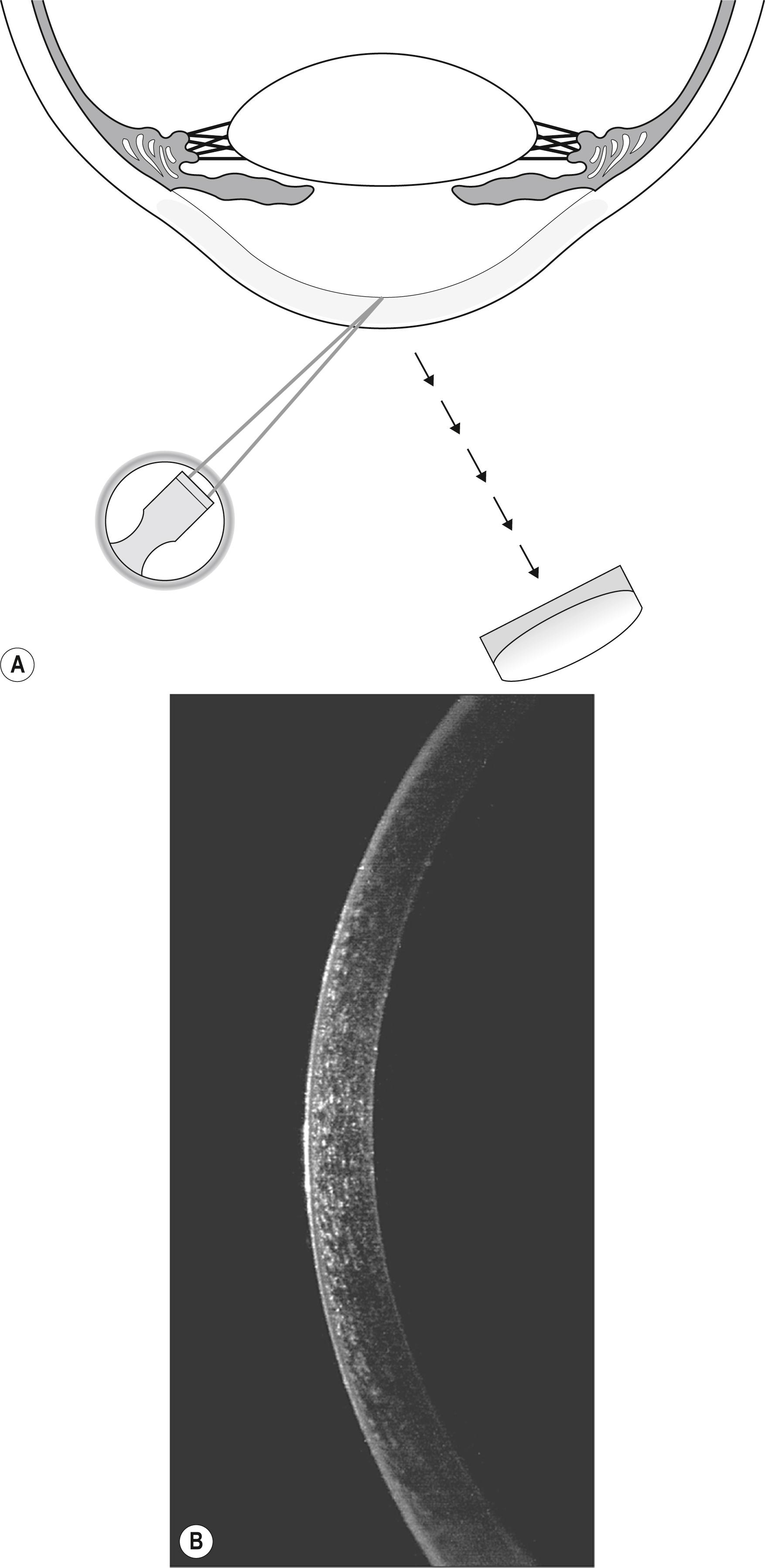
This narrowest slit beam is, in effect, a fine blade of light that makes possible the virtual serial sectioning of transparent tissues in the living eye. The tangential presentation of these “light slices” facilitates an essentially cross-sectional view of the cornea and lens even though these structures are largely parallel with the plane of observation. The sharply focused light is completely confined to the optical section, reducing scatter and maximizing contrast between the illuminated section and the dark, unilluminated surround. The result is a clear, basically uncompromised view of the tissue within the beam. As the slit beam is projected from an increasingly lateral position (away from the axis of the biomicroscope), the greater angular presentation has the effect of increasing the distance between the anterior and posterior surfaces of the structure under study. This increase serves to clarify intrastructural relationships and localization of abnormalities within.
This capability represents the most selective and most isolating manner in which such tissue may be illuminated and observed ( Box 7.3 ). For maximum effectiveness, the light intensity is set to maximum and the slit beam is diminished in width to a point just before the optical section loses structural integrity. The thinner the beam, the more selective the optical section, thus producing finer delineation of information within that section. Beam width, however, should never be reduced to the point at which information is compromised because of light loss.
Edema
Stromal opacities
Marginal dystrophy
Kayser-Fleisher ring
Fuchs dystrophy
Corneal pannus
Epithelial defect
Corneal infiltrates
Furrow dystrophy
Lens opacities
Dellen
Microcysts
Bullae
Ectatic changes
Anterior chamber depth
Tear film deficiency
Corneal thinning
The transparency of the cornea coupled with its propensity for both primary and secondary expressions of numerous diseases makes it the most important component of the eye to section with light. Although remarkably transparent, normal corneal tissue is sufficiently relucent to reflect the narrow slit beam and articulate the optical section.
A high-magnification view of the optical section will produce excellent discrimination of the substantial corneal layers. Beginning with the tear film, each layer may be selectively examined for departures from the normal ( Fig. 7.12 ). The normal tear film will “flow” dynamically within the slit beam following each blink of the eyelids. Its reflectivity will alter with the amount of refreshed, protective lipid on its surface, but it will maintain a constant thickness and a smooth anterior face. The epithelium is seen as a line of nonreflectance or greatly diminished reflectance between reflections from the tear film and the Bowman layer, which is contiguous with (and largely indistinguishable from) the anteriormost reflection from the stroma. The stroma itself is quite transparent. By encroaching on the zone of specular reflection, however, its reflectance can be enhanced considerably for better visualization of its structure. The optical section will terminate with the heightened reflection from the endothelium.
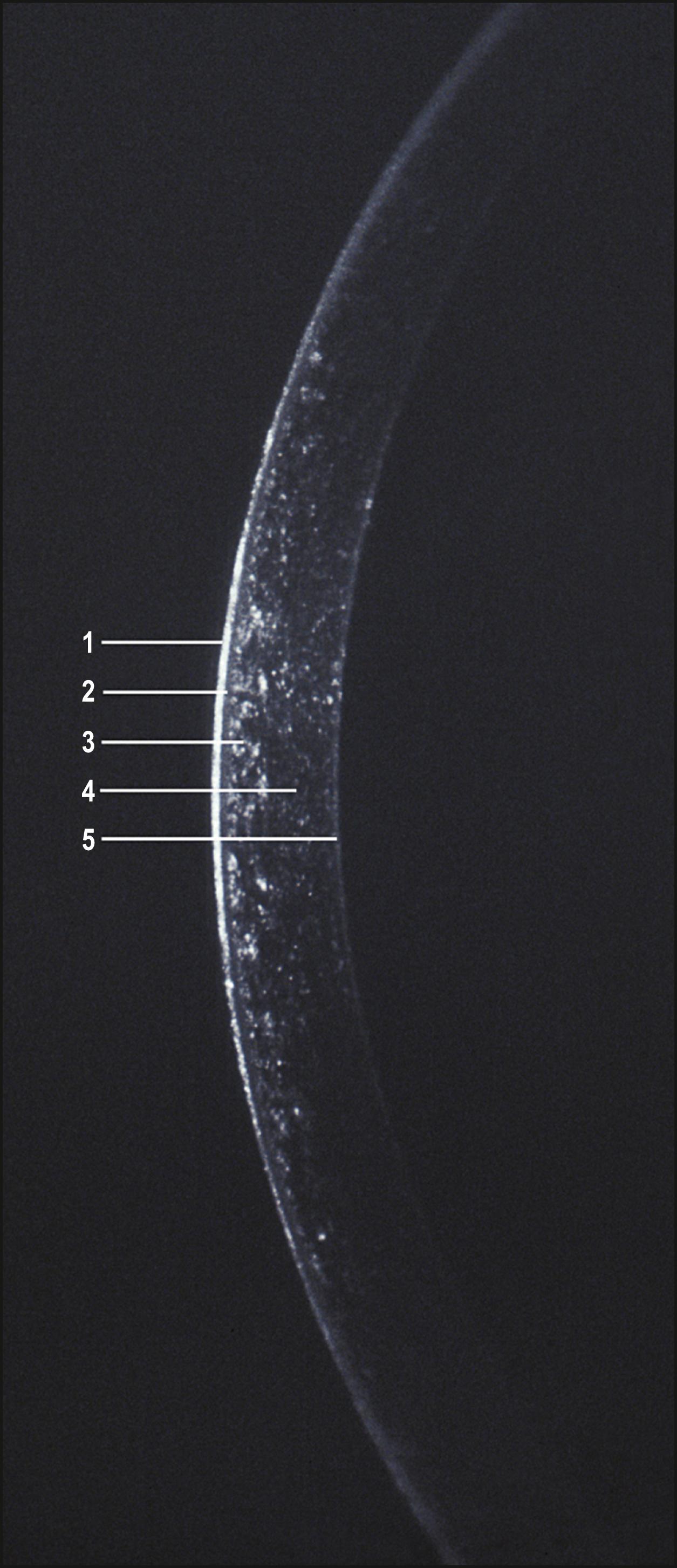
As corneal transparency is lost to disease or injury, an increased amount of light is reflected. (The condition of a sclerotic, totally opaque cornea represents the extreme, or terminal, end of this transmission spectrum. In this condition, much of the light is reflected by the surface, limiting visual access to deeper layers. In such cases, moderate amounts of illumination will be considerably more informative, and a thorough examination will necessitate the use of indirect techniques, as discussed later in this chapter.)
An inadequate tear film will present as a compromise to the normally smooth, unbroken reflection of the beam ( Fig. 7.13 ). An edematous epithelium will become dimensional in the optical section and reflect increasing amounts of light ( Fig. 7.14 ). Changes in focal density will be isolated to the anterior, middle, or posterior cornea ( Figs. 7.15 and 7.16 ). The Descemet membrane will become visible when abnormal mechanical forces alter its normal topography ( Fig. 7.17 ). The endothelium will reflect increased amounts of light when it is affected by changes such as Fuchs dystrophy ( Fig. 7.18 ). Within the visual axis, relatively mild expressions of tissue compromise can cause notable symptoms. Determining exact location and distribution is significant for arriving at a diagnosis.
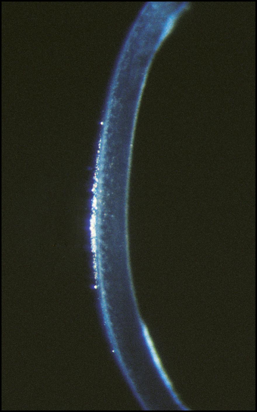
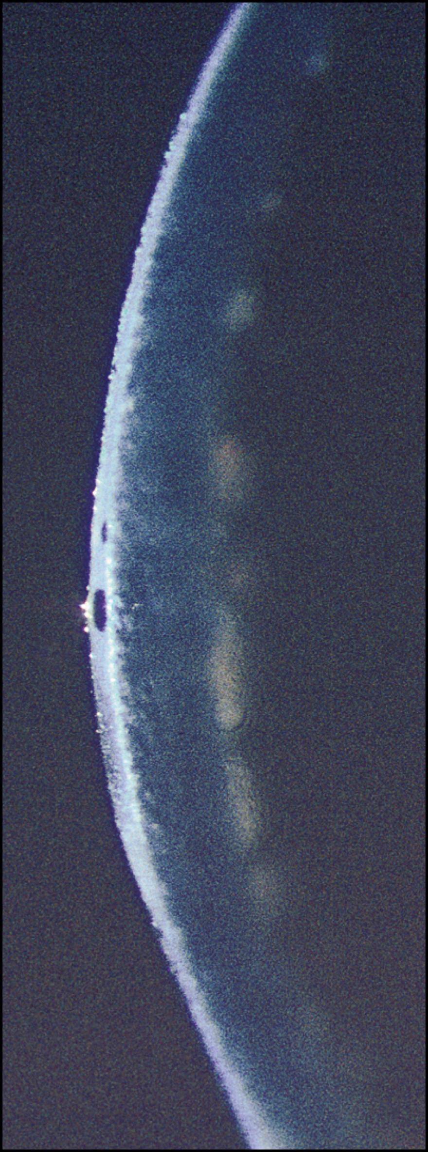
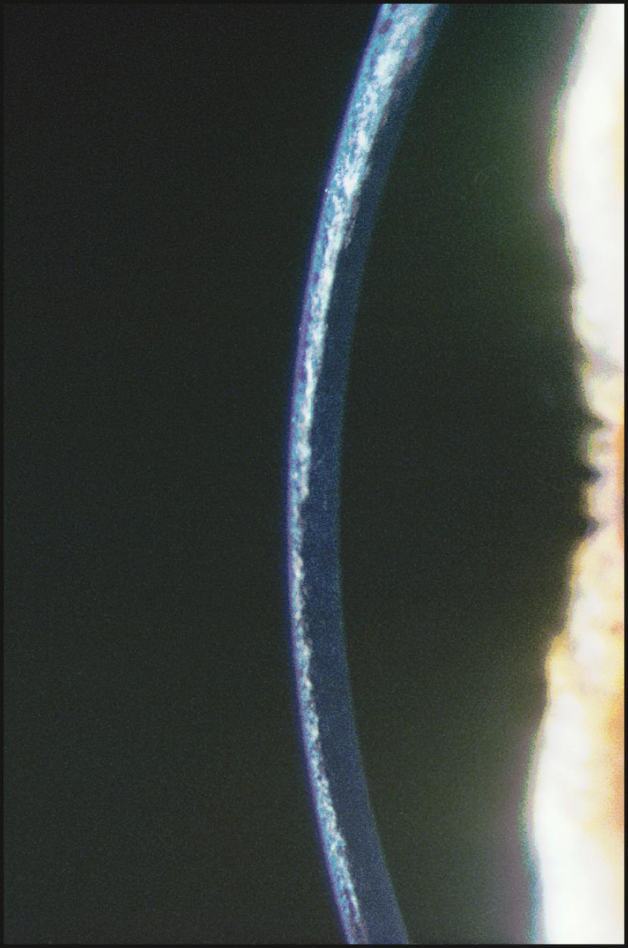
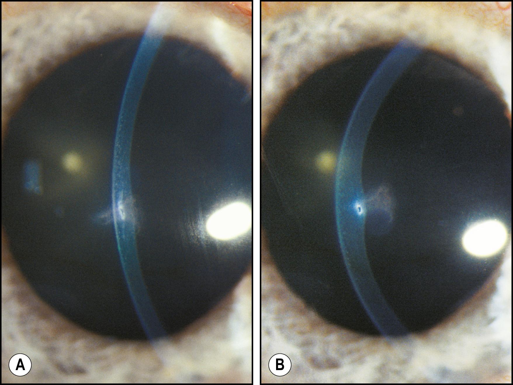
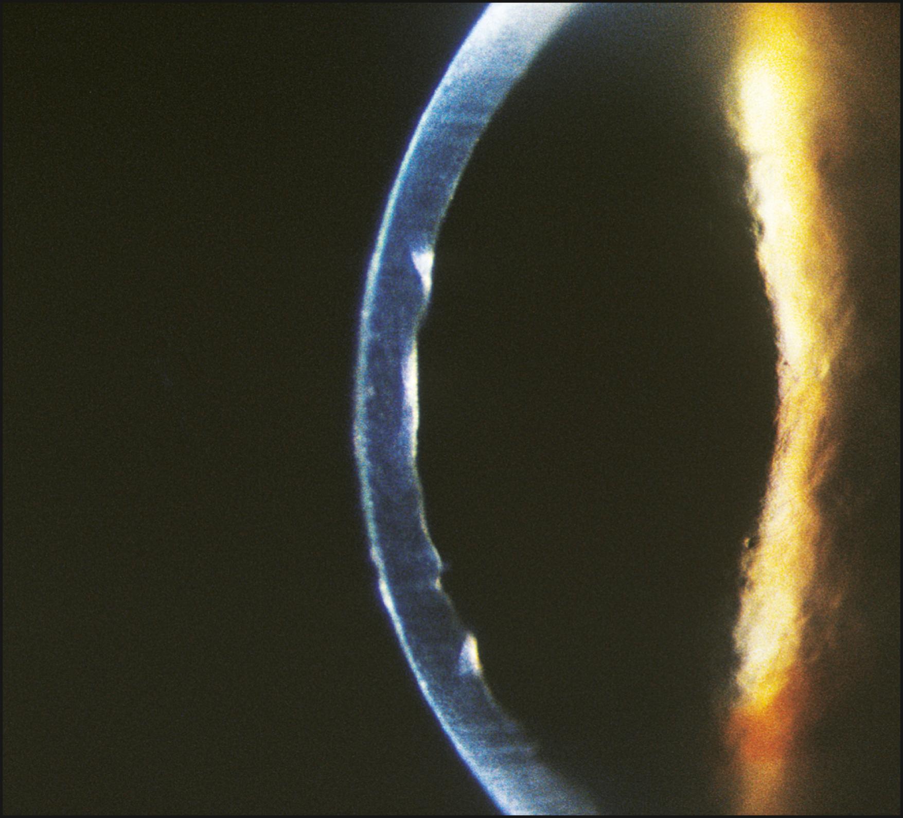
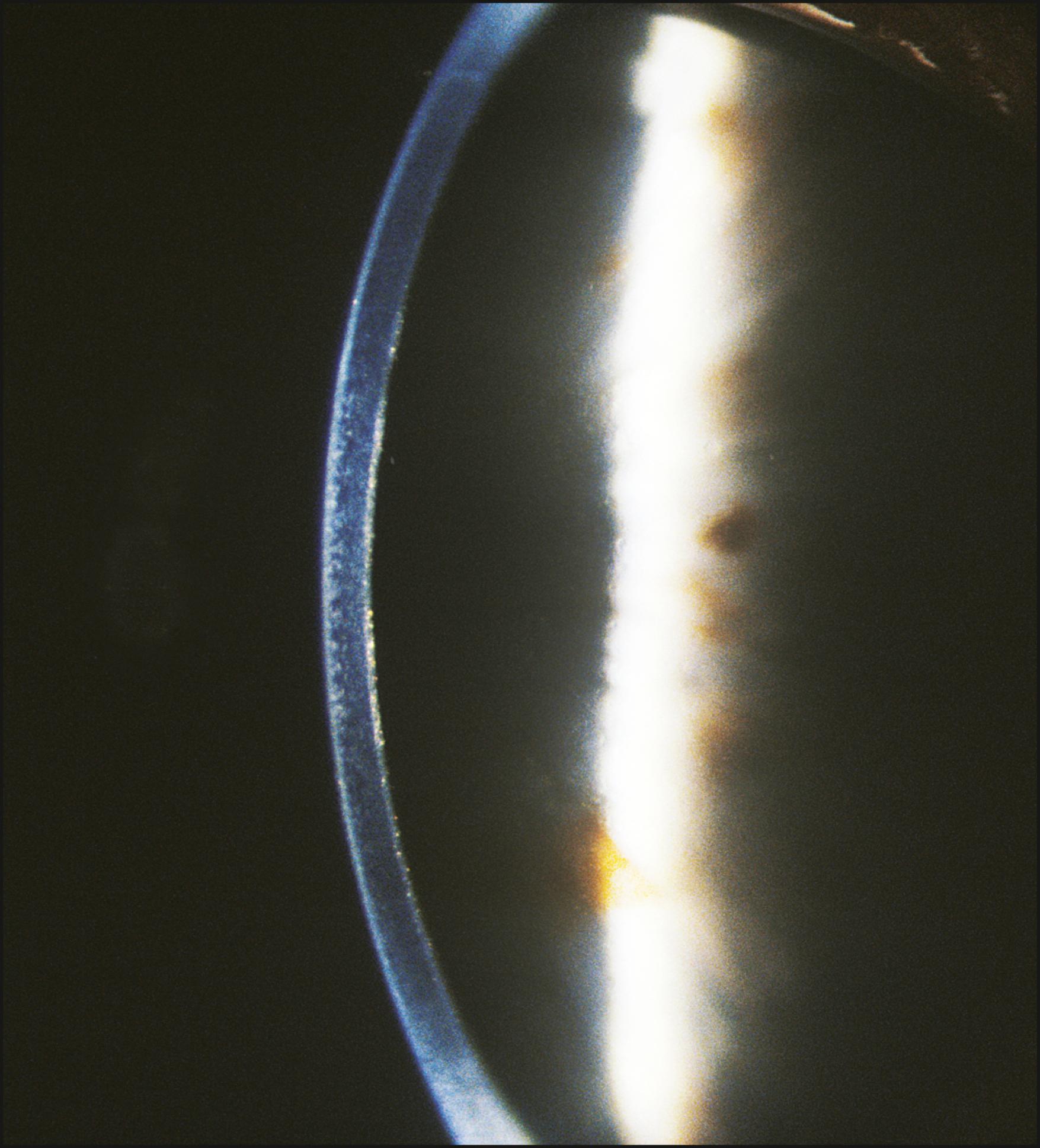
As the cornea is scanned in optical section, the relationship of the anterior to the posterior surface is also observed for changes in normal thickness and curvature. Ectatic changes, such as keratoconus or keratoglobus, will become readily apparent ( Fig. 7.19 ). Focal elevations or depressions also become obvious as the slit beam deviates toward or away from the light source ( Fig. 7.20 ).
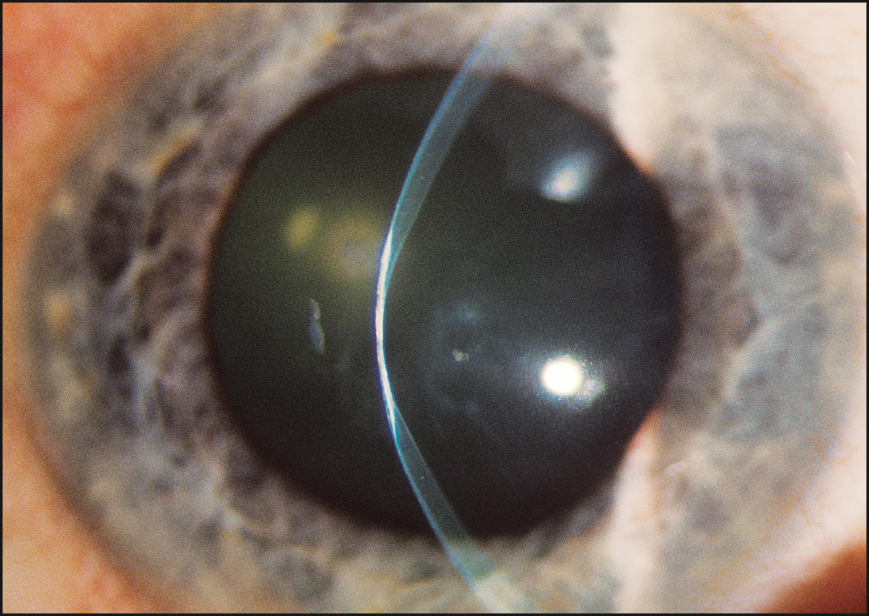
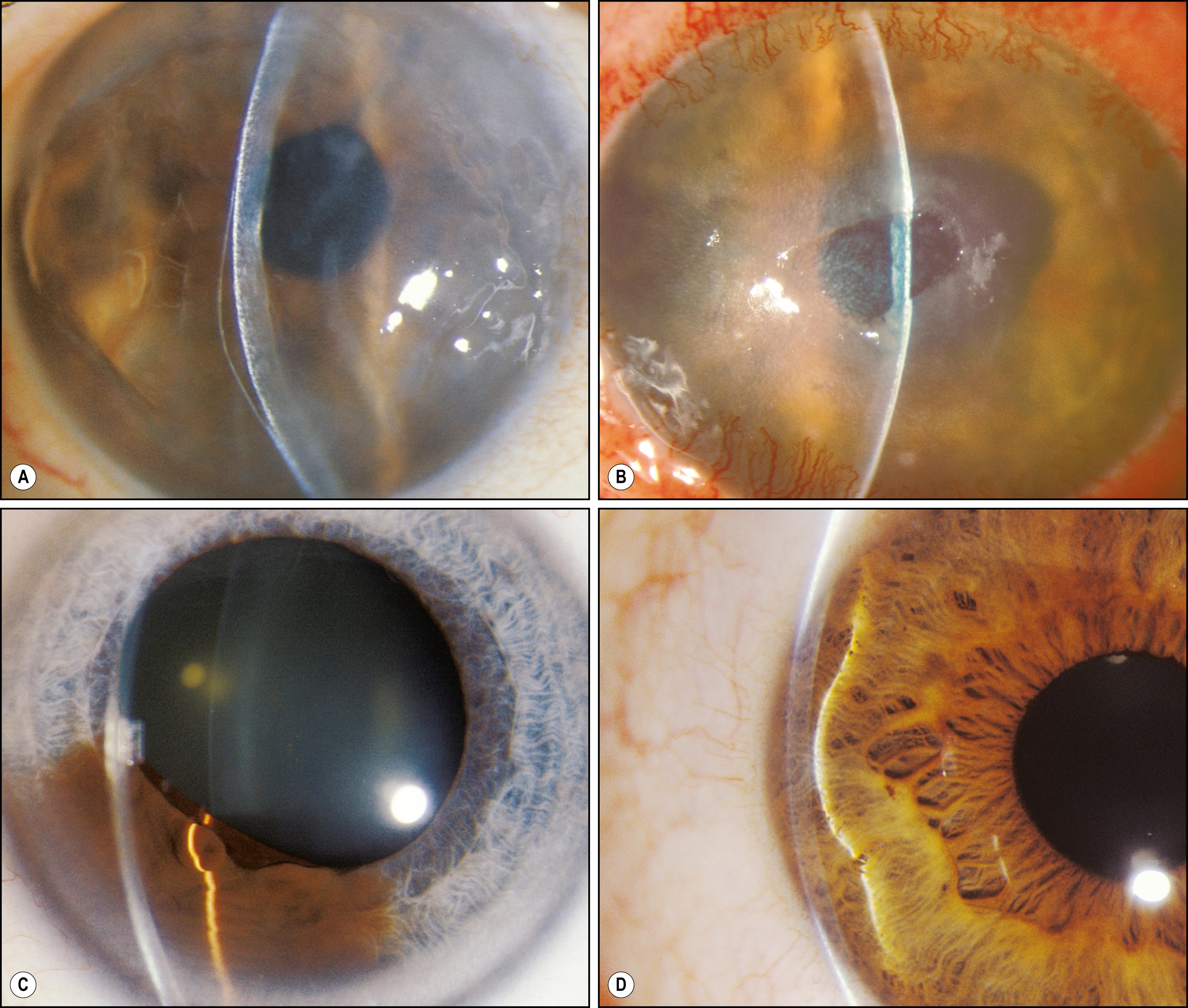
It is important to apply the narrow slit beam to all ocular surfaces. A thorough scan of the lid margins, the bulbar and palpebral conjunctiva, the plica, caruncle, and corneal limbus will provide confirmatory information or add to what was gleaned using the modalities described earlier. The narrow slit beam is most effective in detecting topographic changes in these structures ( Fig. 7.21 ). Follicles, papillae, or other dimensional alterations are well stated in this manner. All tissue will demonstrate some penetration by the beam. The degree of penetration is variably limited by the optical density of the tissue under study. Although actual penetration may be minimal, the information produced can be valuable. Of equal or greater importance is the indirect, proximal illumination simultaneously achieved (see the later section titled “Indirect Illumination”).
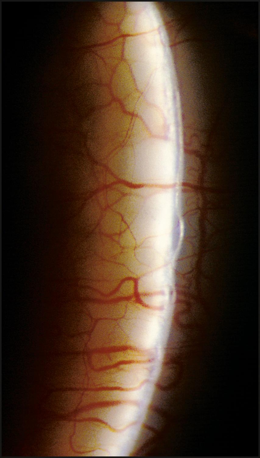
The relationship between the cornea and iris is also evaluated with a narrow slit beam. By projecting the light from a moderate angle and observing the distance between the reflections from the cornea and the iris, a good estimate of anterior chamber depth can be obtained. Observing this relationship at the limbus provides information regarding the grade of the angle. A completely closed segment of the angle is indicated by a contiguous presentation of corneal and iris reflections ( Fig. 7.22 ). In a similar fashion, anterior synechiae may present as focal areas of contact between the reflected beams at the posterior corneal surface. This condition is confirmed by observing the slit beam coursing up the side of the tented iris tissue to make contact with the reflection from the posterior corneal surface ( Fig. 7.23 ).
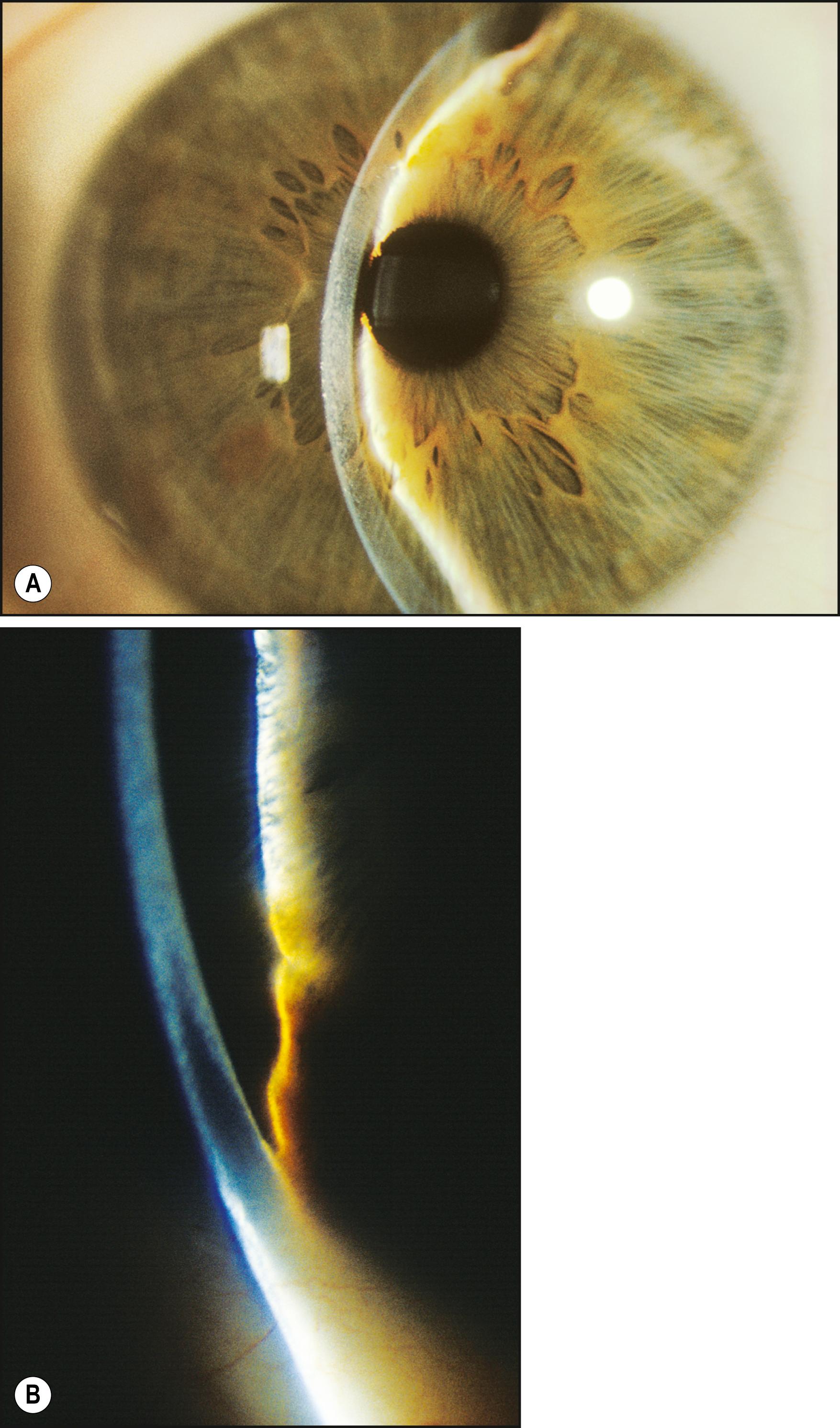
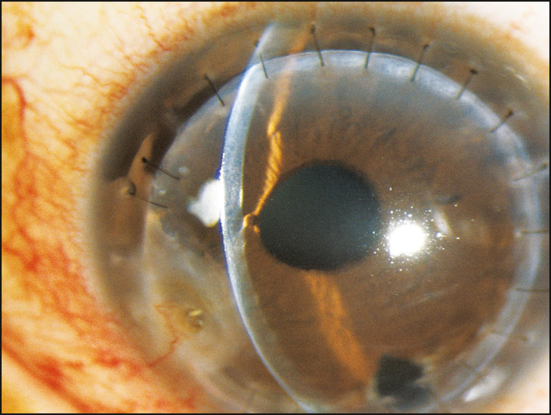
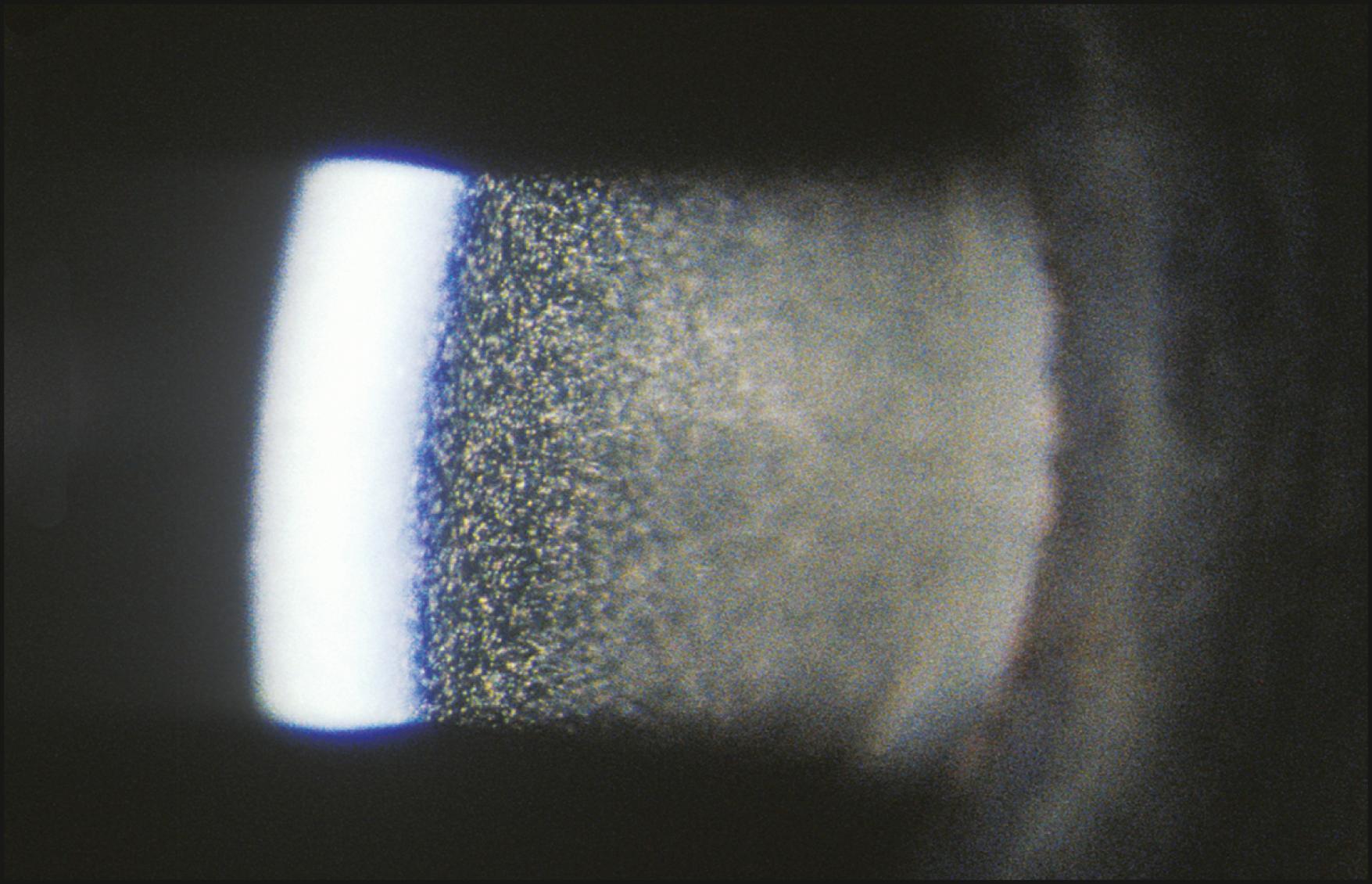
Based on the Tyndall phenomenon, pinpoint illumination is maximally effective at isolating aqueous cells and flare. The anterior chamber is considered optically empty, as its contents do not reflect sufficient light to express the beam in the normal state. The cells and protein that present in response to local inflammation, therefore, can be seen readily when isolated within the well-defined, narrow tunnel of light produced by pinpoint illumination.
A small round beam of high intensity is directed tangentially through the anterior chamber, and the focal point of the light (and the biomicroscope) is swept through the aqueous to determine the presence and density of cells and flare. For maximum contrast, when conditions permit, cells and flare should be observed against the dark background of a dilated pupil while minimizing the light striking the iris.
Although the “pinpoint” or “pencil of light” configuration represents the most discriminating technique ( Fig. 7.24 ), the standard grading system used to describe the concentration of cells and flare assumes the use of a beam approximately 1 by 3 mm in size. The number of actual cells seen simultaneously within that beam is the stated degree of the condition. The amount of abnormal protein is determined by the examiner’s impression of the reflectivity (or Tyndall effect) of the aqueous. The degree of expression of these two conditions is stated in terms of one to four or more cells and/or flare ( Fig. 7.25 ).
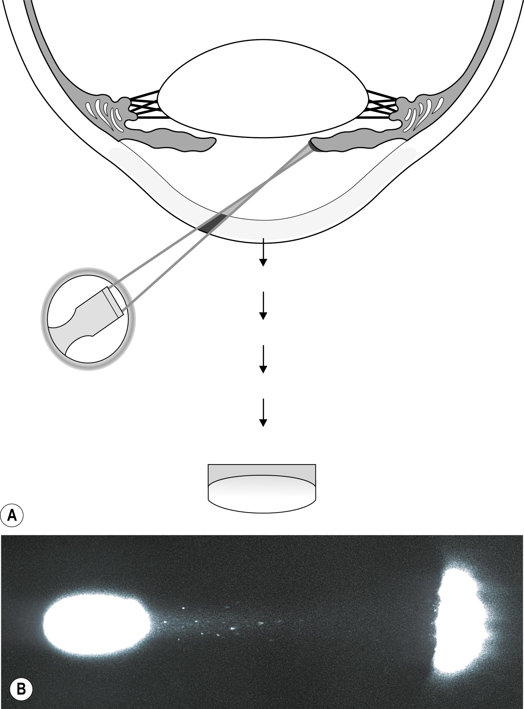
The bright mirrored reflections of light sources are considered regular, or specular, reflections as opposed to the more common irregular reflections whereby most objects are seen. Specular reflections are subject to Snell’s law of optics, which states that the angle of reflection equals the angle of incidence. This suggests a level of difficulty associated with the location of such a reflection that is simply not present when the eye is being examined. On the curved ocular surfaces, specular reflections are easily elicited. The convex cornea and the high reflectivity of its anteriormost layer, the tear film, combine to make such reflections more or less ever-present companions during the course of an examination. Although they may sometimes be annoying, these reflections are, in fact, of great value for gathering information about the condition of the eye.
As the eye is viewed in direct illumination, the zone of specular reflection is studied as an expression of surface integrity. This evaluation should be performed under a fairly low light level so as to diminish scatter and make visible detail within the zone of specular reflection. The area of specular reflection is not only a mirror image of the source but also faithfully mirrors the topographic condition of the surface on which it rests. Therefore a compromised corneal surface will produce an abnormal reflection of the light source. Broken or granular reflections may indicate an inadequate tear film, the presence of foreign material, or a compromise to underlying tissue expressed as an alteration from normal topography. A greatly diminished or irregular reflection is always a clear sign of abnormality ( Fig. 7.26 ).
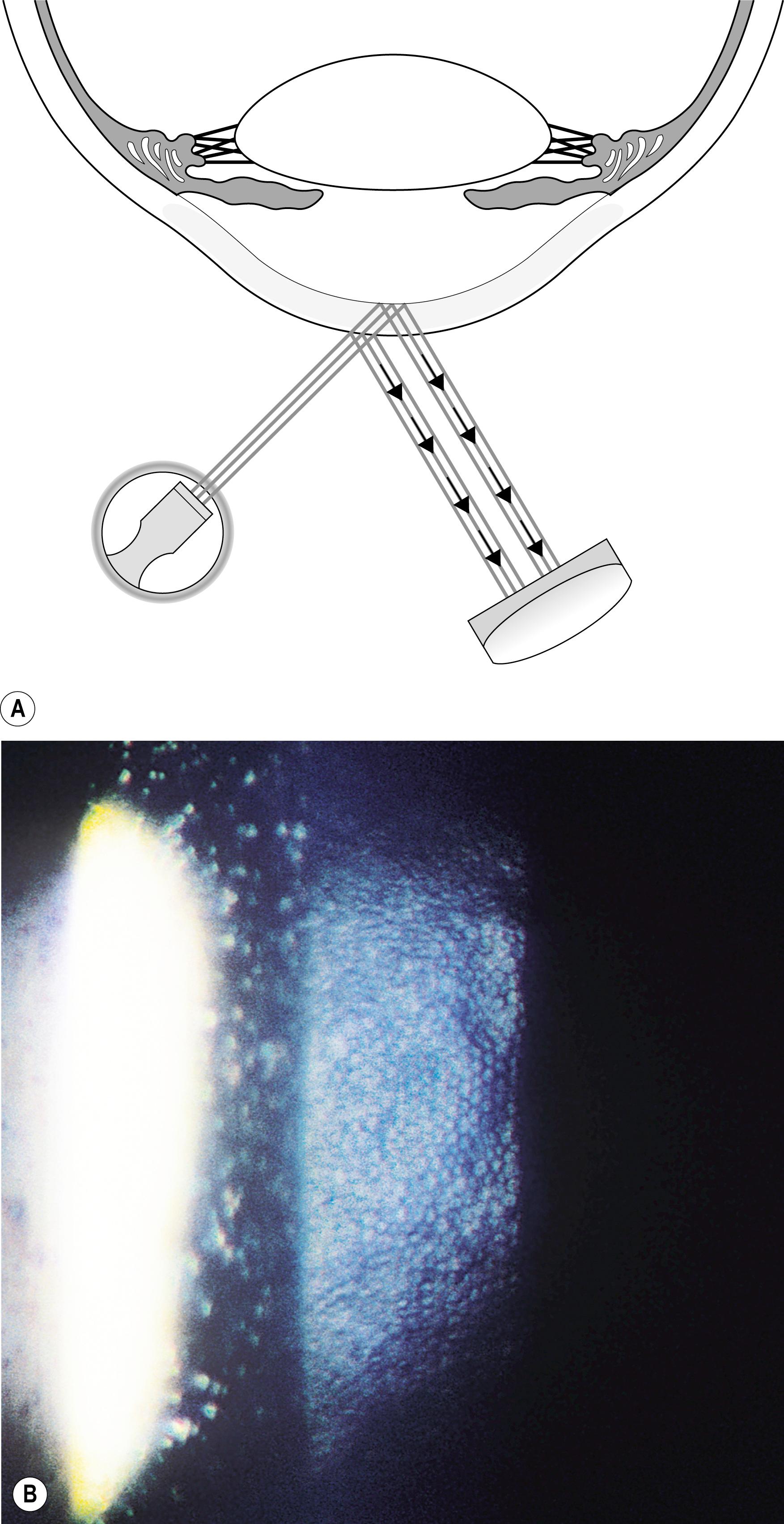
The most important application of the specular reflection is in the evaluation of the corneal endothelium. While not expressly difficult, this technique may prove initially challenging. The reflectivity of the endothelial surface is so much lower than that of the tear film layer that the specular reflection may not be appreciated even when present. An angular difference of 30–40 degrees between the slit illuminator and the biomicroscope will make the task easier by producing greater separation between the two reflections. Moving the incident beam laterally across the face of the cornea will elicit the bright specular reflection from the tear film layer. By observing the adjacent area on the side opposite the light source, the more demure endothelial reflection will be seen. Moving the biomicroscope forward approximately 0.5 mm will bring into focus the endothelial layer, and cellular detail should become apparent. To obtain a clear view of endothelial cells, especially those that populate the uncompromised young cornea, a magnification of 25× to 40× is required ( Fig. 7.27 ). When such levels of magnification are not available, the endothelium can still be evaluated with this technique. The reflection is observed for continuity and uniform intensity as the light is played across the endothelium. When conditions such as guttae are present, the homogeneity of the reflection is interrupted ( Fig. 7.28 ).

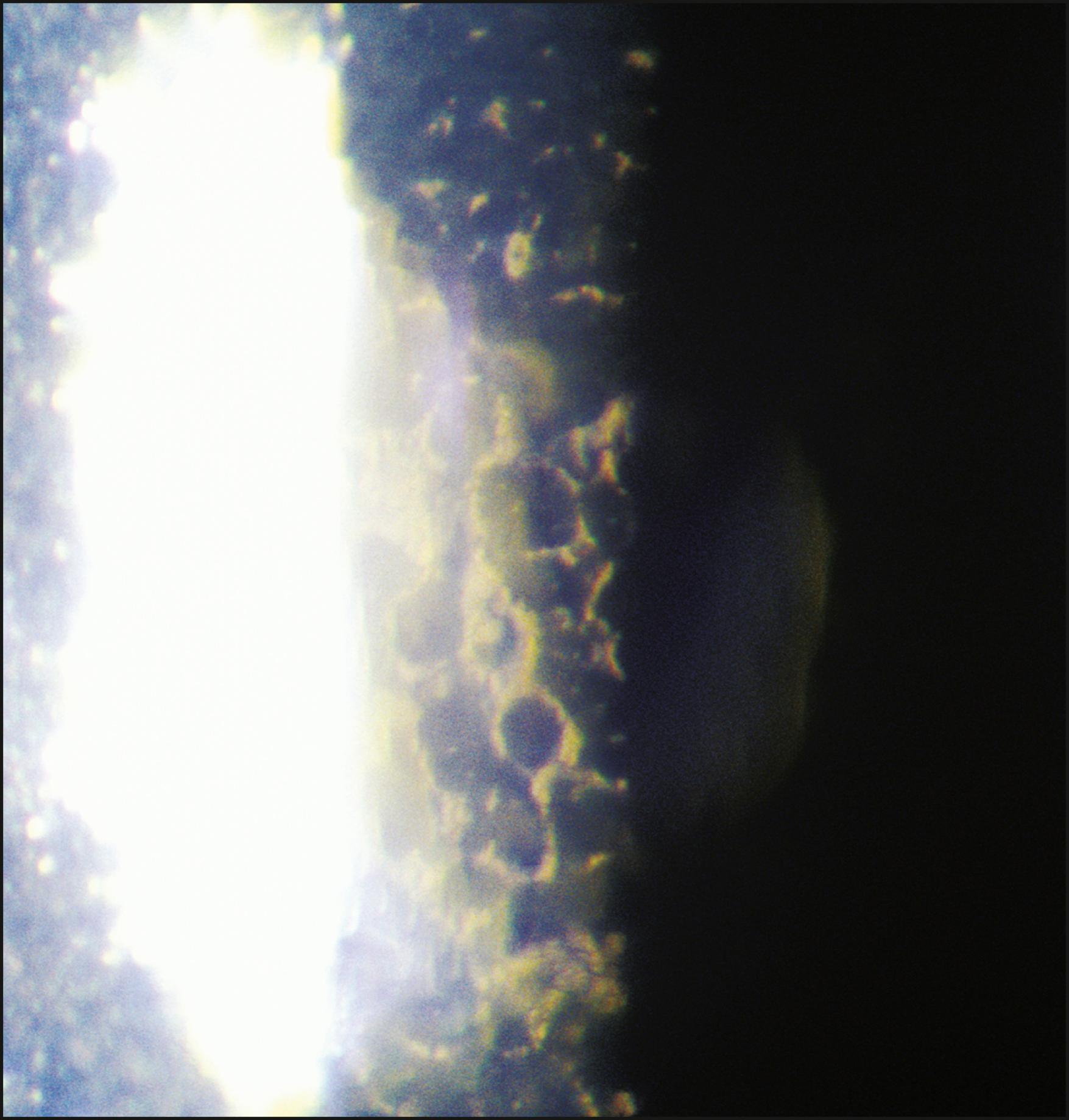
In severe expressions of disease-related endothelial compromise, such as advanced Fuchs dystrophy, the reflection may become totally altered from the normal. Coalesced guttae may cause it to appear patchy or quite dark overall and, even at high magnification, information about individual cell borders may not be present ( Fig. 7.29 ). In such conditions, even specular micrography may fail to produce satisfactory information regarding cell morphology or density.
The specular reflection can also be used to examine the surface of the conjunctiva and the anterior and posterior surfaces of the lens.
In proximal illumination, the light is directed to strike an area just adjacent to the area to be examined. The principal subject, therefore, is illuminated by light transmitted through tissue. The effect is one of retroillumination from deeper layers. It is remarkably effective for observing subsurface changes in tissue of sufficient opacity to prevent light penetration to the desired level with direct illumination ( Fig. 7.30 ). Similarly, proximal illumination can facilitate location and determination of size and shape of an imbedded foreign body or one obscured by soft tissue reaction. It can also be helpful in gathering additional information about abnormalities that are apparent in direct focal illumination. By observing conjunctival or skin alterations with this modality, the specular reflections produced by direct illumination are eliminated, and another, valuable perspective is obtained in what becomes a form of retroillumination ( Fig. 7.31 ).
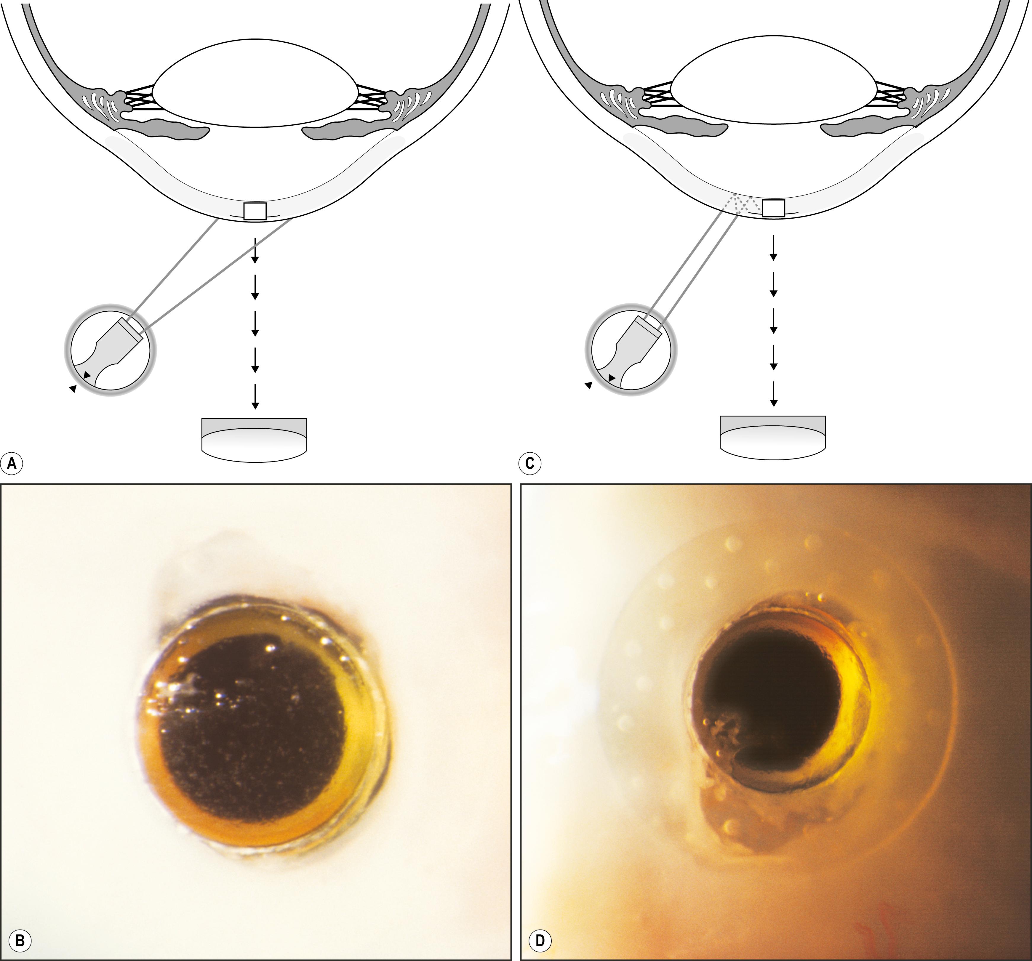
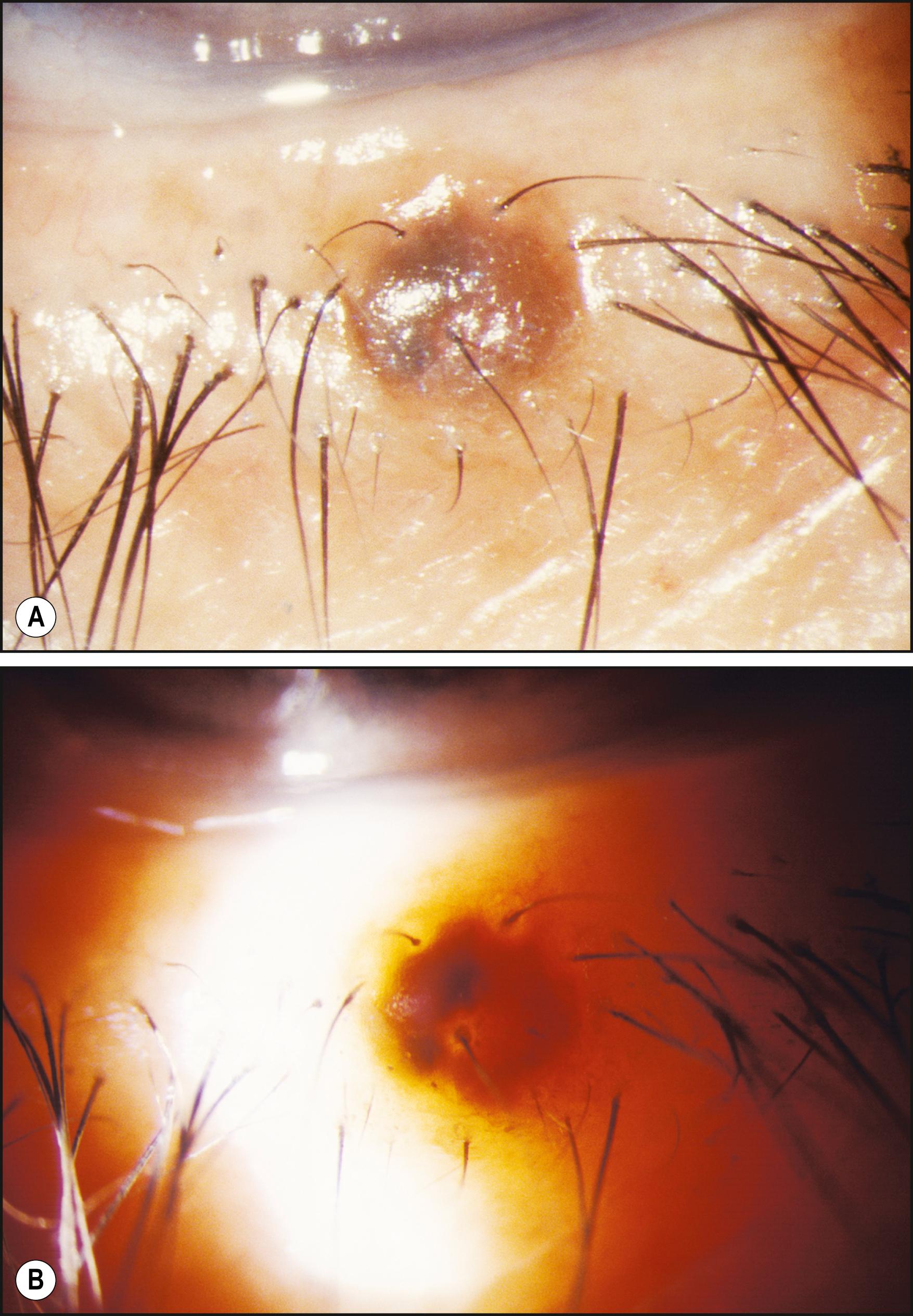
The benefits of proximal illumination are probably exploited more frequently than may be realized. A scan of the conjunctiva in direct focal illumination (e.g., with a narrow slit beam) includes making use of the information seen in the adjacent area of proximal illumination. Proximal illumination may not be the conscious goal of the examiner, but information from this zone is nonetheless gleaned. In fact, without it the examination would be incomplete.
When high magnification is used in observations by proximal illumination, the subject area may become sufficiently decentered to make viewing cumbersome. In such cases, the slit illuminator must be decentered from its normal isocentric position to permit centration of the principal subject area within the field of view.
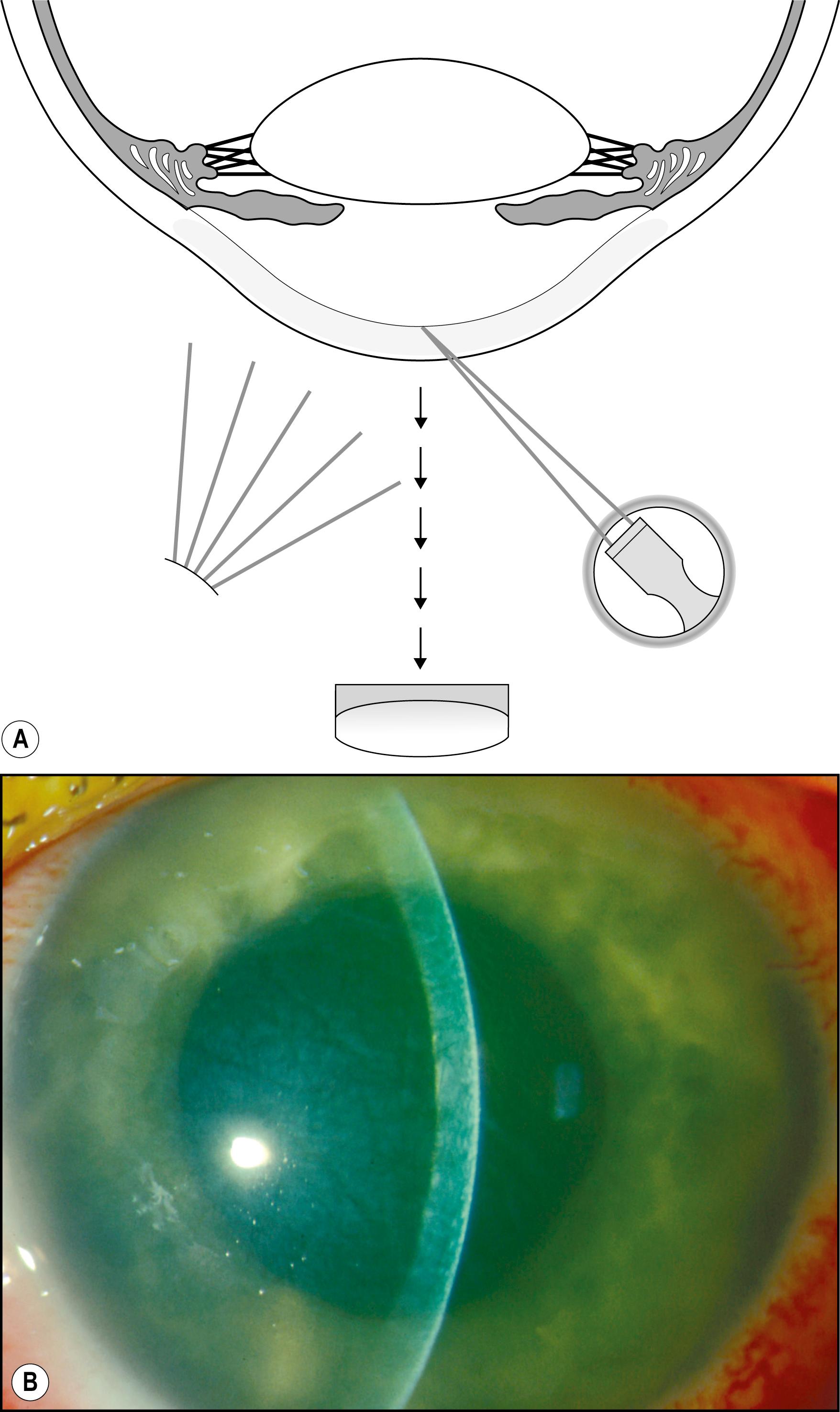
Specifically applicable to the cornea, sclerotic scatter permits the illumination of the entire cornea against a largely unilluminated background. An intense beam of moderate size is directed at the corneoscleral junction. The light travels the breath and width of the cornea by total internal reflection. In the normal cornea, this light passes through the stroma undisturbed and is visible only as a ring of light at the limbus, where it intersects the sclera and is reflected by it. The brightest portion of this ring of light is located directly opposite the source. The normal cornea itself will appear unilluminated. Because of the extreme degree to which the cornea must be decentered to accommodate illumination of the limbus, the slit illuminator must be disengaged from its normal, isocentric relationship with the biomicroscope to allow centration of the cornea within the field of view ( Fig. 7.32 ). In the abnormal cornea, the light that is axially reflected or refracted makes the abnormality visible. The degree to which this light is visible depends on the optical density and other characteristics of the abnormality and the size and intensity of the incident light beam ( Fig. 7.33 ).
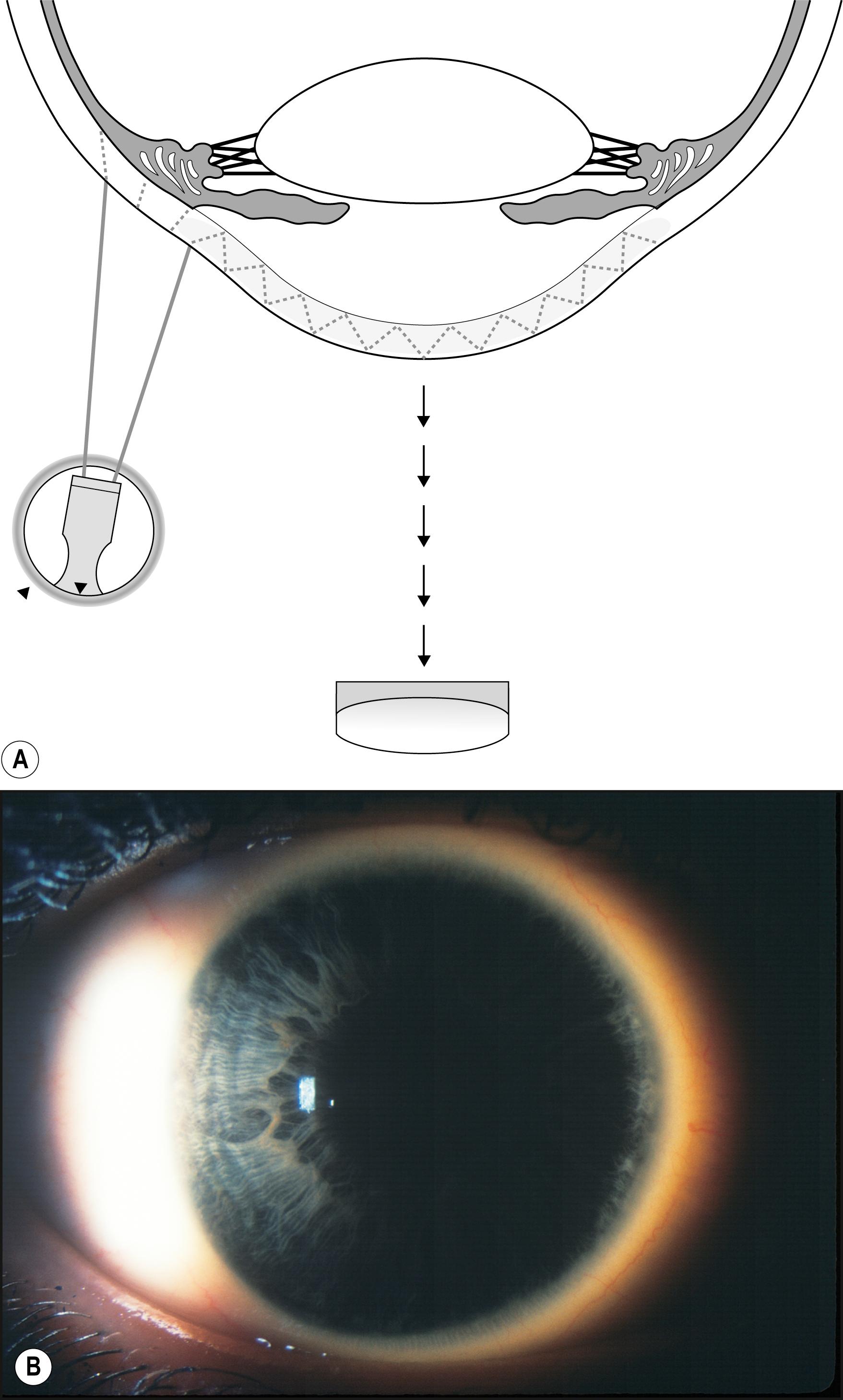
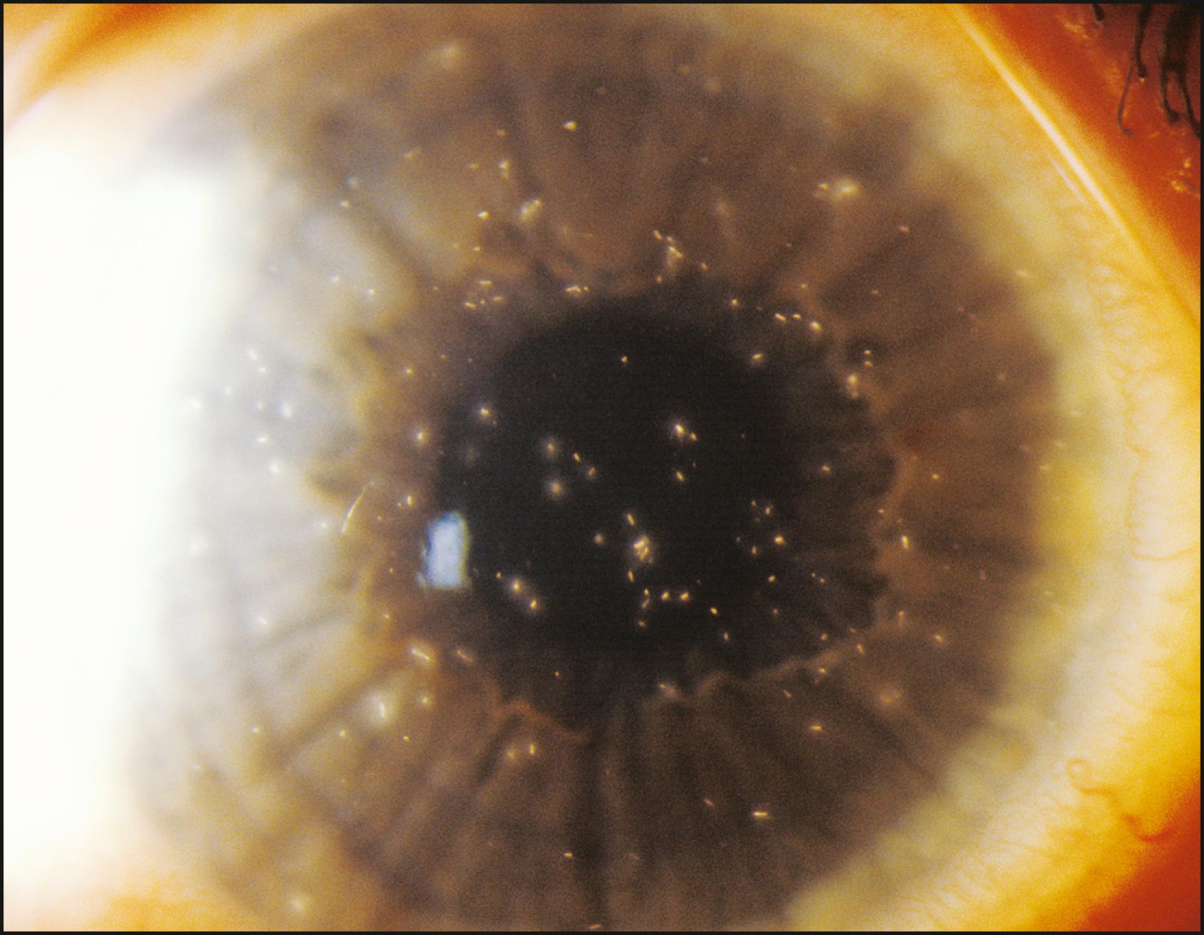
Sclerotic scatter is quite remarkable for its sensitivity to subtle change while yielding information over a large area of distribution ( Box 7.4 ). That combination is not possible with most forms of illumination. The ever-present compromise of “area versus detail” limits each application. Generally the larger the area of simultaneous illumination, the more light will be scattered, producing a corresponding loss of fine detail. However, in sclerotic scatter, as the cornea is illuminated by a source that is comparatively small (the size of the beam directed at the limbus), this technique is not strictly subject to this limitation. In reality, sclerotic scatter provides a simultaneous view of a large expanse of cornea, making it useful in identifying certain disease entities through recognition of a characteristic overall pattern. In certain instances, the incidental light that falls on the iris, especially one of light pigmentation, may become a significant negative factor. Thus a condition of subtle expression (e.g., cornea verticillata in Fabry disease) can be best appreciated against the dark background of a dilated pupil ( Fig. 7.34 ).
Corneal foreign bodies
Corneal edema
Keratic precipitates
Verticillata
Interstitial keratitis
Granular dystrophy
Radial keratotomy scars
Hydrops
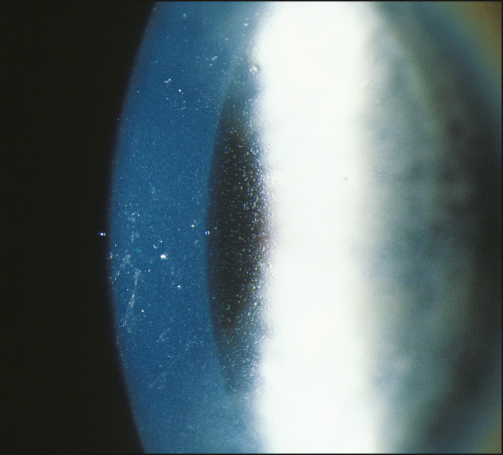
Representing two distinct forms from the standpoint of how they function, direct and indirect retroillumination from the iris are most informative when used together. This combined technique is the most important to the thorough examination of the cornea. It actually produces three types of illumination with corresponding zones of information. With the beam applied tangentially, the area of the cornea observed against the directly illuminated iris (direct retroillumination from the iris) demonstrates alterations that are chiefly opaque. The zone of cornea that falls on either side of the illuminated background (i.e., cornea that lies in front of unilluminated iris or pupil—the zone of indirect retroillumination from the iris) demonstrates primarily refractile changes and changes of low optical density. Of greatest importance is the interface between light and dark backgrounds, where the most subtle changes may be seen. Abnormalities that both refract and reflect light become most dimensional in this zone between light and dark backgrounds.
Technically, this juncture is an interface rather than a true zone. Because the biomicroscope (and therefore the slit beam) is focused at the level of the cornea, however, the interface is formed by divergent rays, resulting in a blurred image at the level of the iris. Because this blurred image of the interface appears to occupy space by virtue of its broader appearance, it becomes a zone in the practical sense ( Fig. 7.35 ). The entire cornea can thus be examined for both subtle and obvious alterations. The beam of light is applied tangentially and moved across the cornea while the three zones are observed simultaneously, with particular attention paid to the interface of light and dark backgrounds. To ensure that all information about the cornea has been gathered with this modality, the scan should be repeated with the light applied from both the temporal and nasal sides.
Many entities are easily visualized and identified in this manner ( Box 7.5 ). Lattice dystrophy, with its characteristic signature, is seen in all three zones of illumination (see Fig. 7.35 ). Folds in the Descemet membrane are best seen in indirect retroillumination from the iris, but close to the interface of light and dark backgrounds ( Fig. 7.36 ). The classic, bubble-like microcysts characterizing Meesmann dystrophy are most dimensionally described within the interface zone ( Fig. 7.37 ). Fig. 7.38 demonstrates the effective use of the illuminated iris to delineate overlying dense corneal foreign bodies, and Fig. 7.39 shows the effectiveness of indirect retroillumination from the iris in highlighting subtle, translucent corneal foreign bodies against a dark pupil and unilluminated iris.
Lattice dystrophy
Corneal foreign bodies
Meesmann dystrophy
Map-dot-fingerprint dystrophy
Cornea farinata
Descemet folds
Keratic precipitates
Thygeson superficial punctate keratitis
Corneal infiltrates
Early edema
Filaments
Microcysts
Fuchs dystrophy
Corneal scars
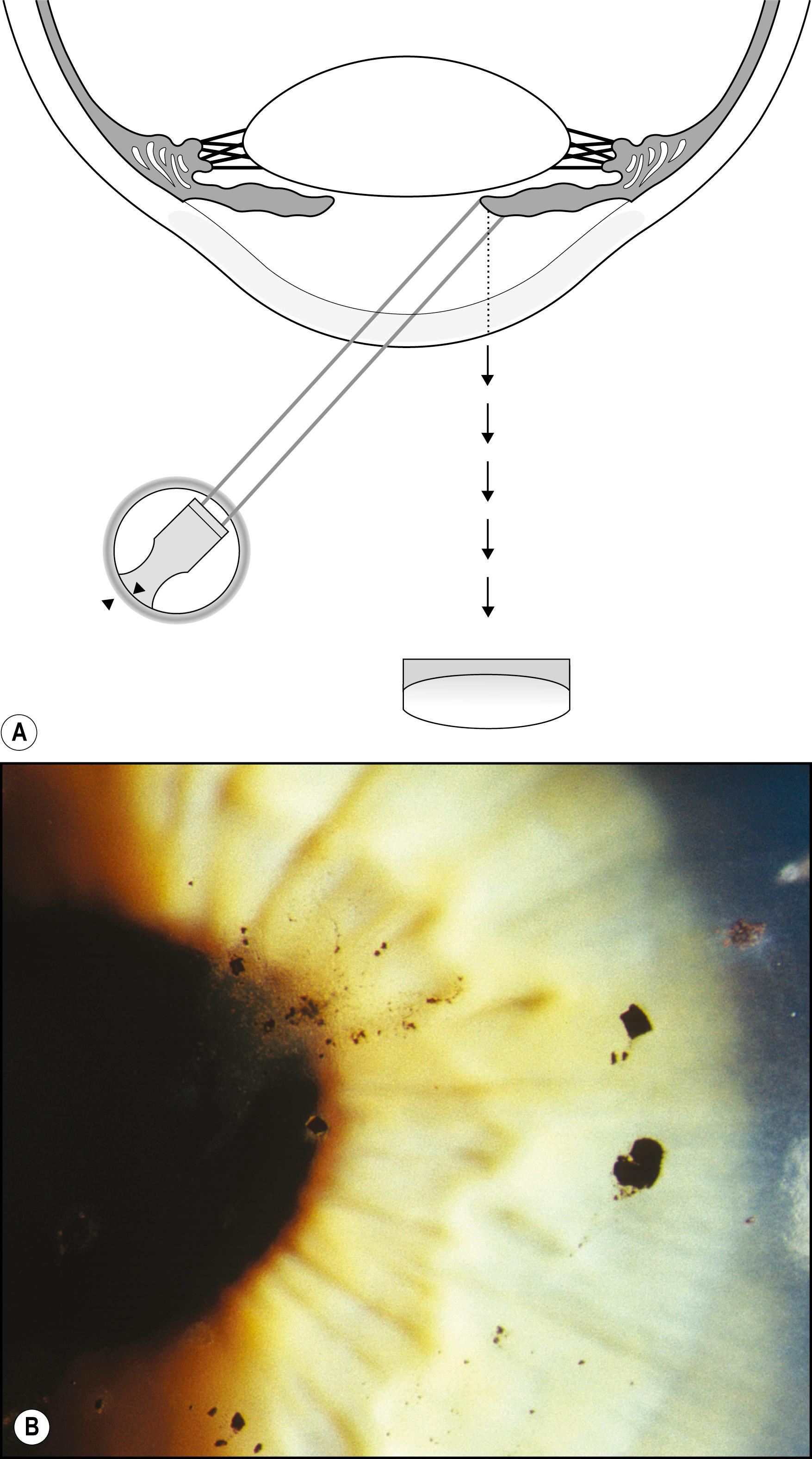
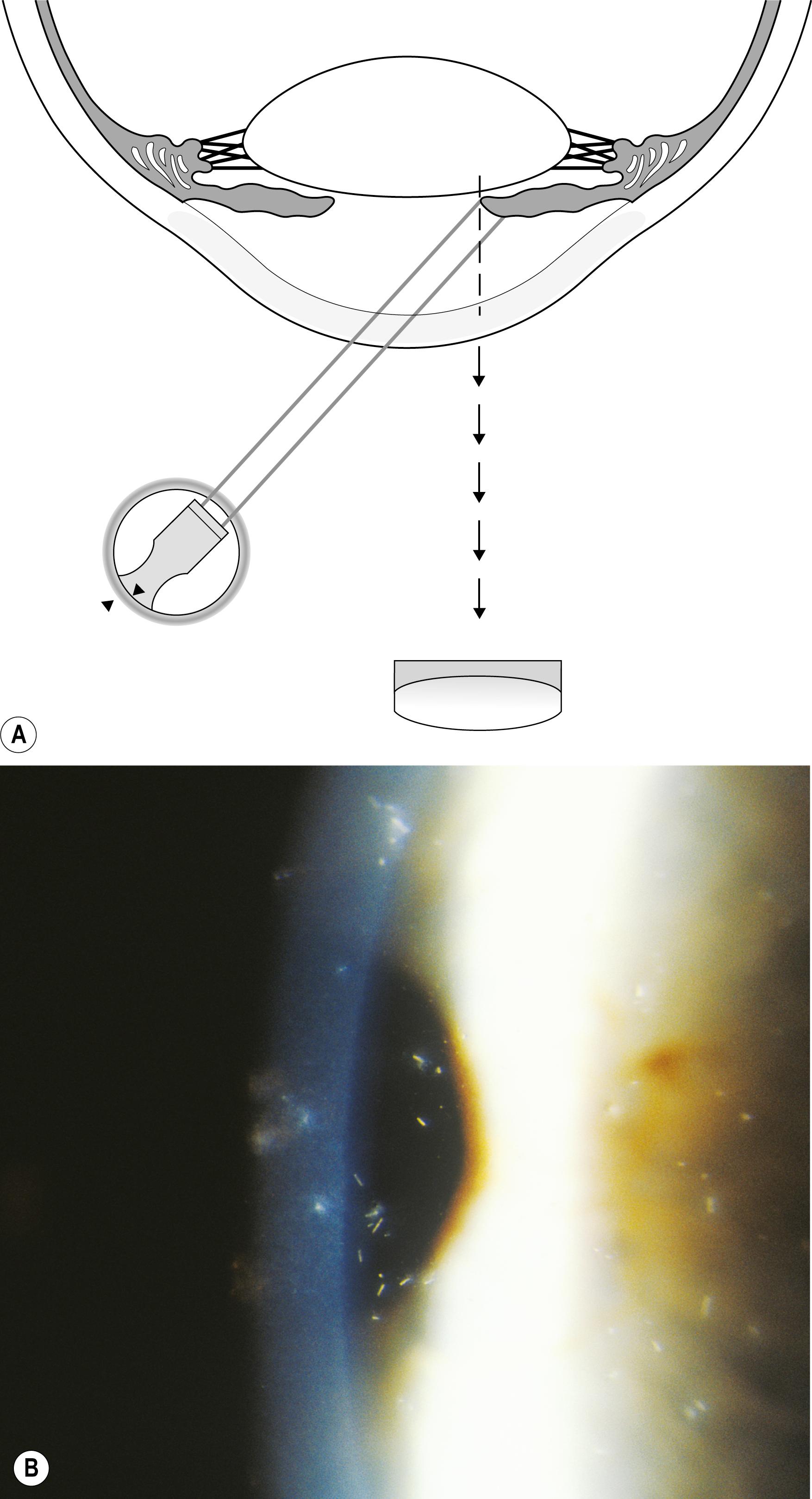
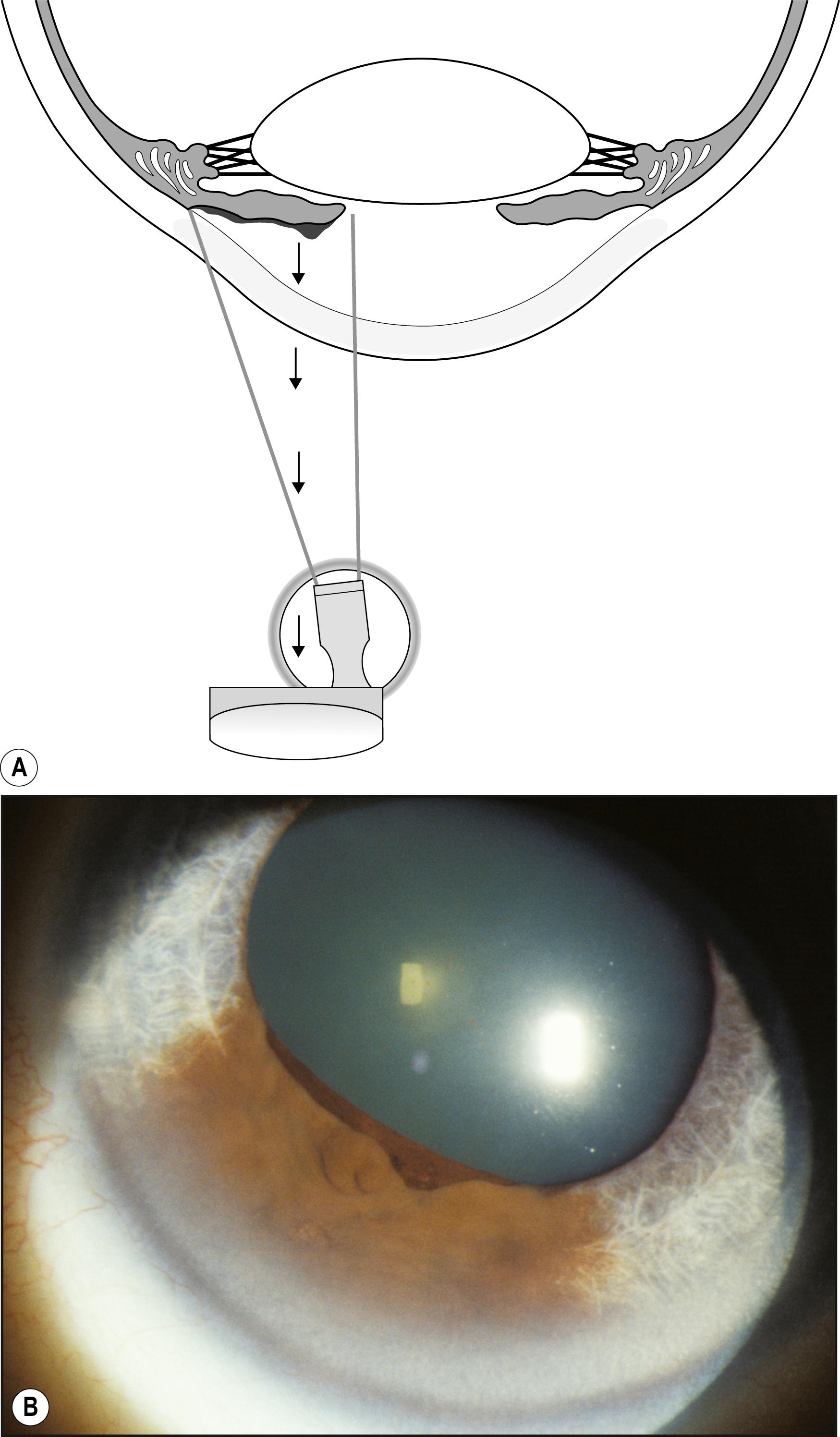
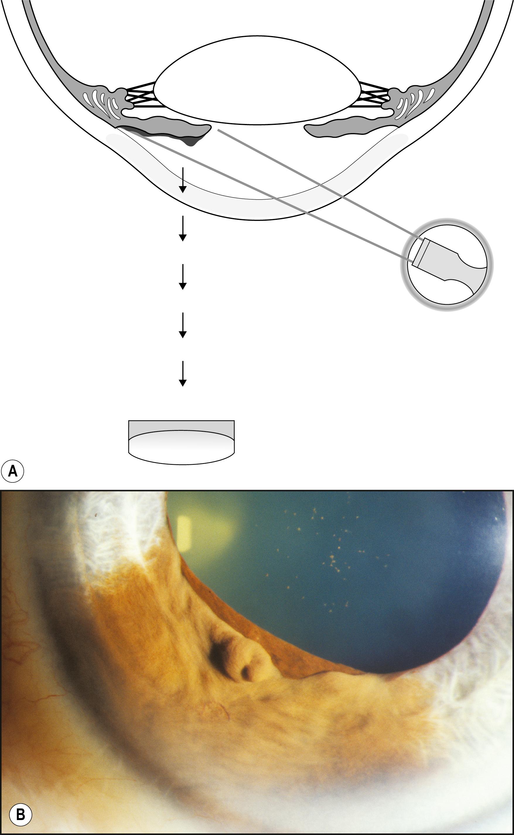
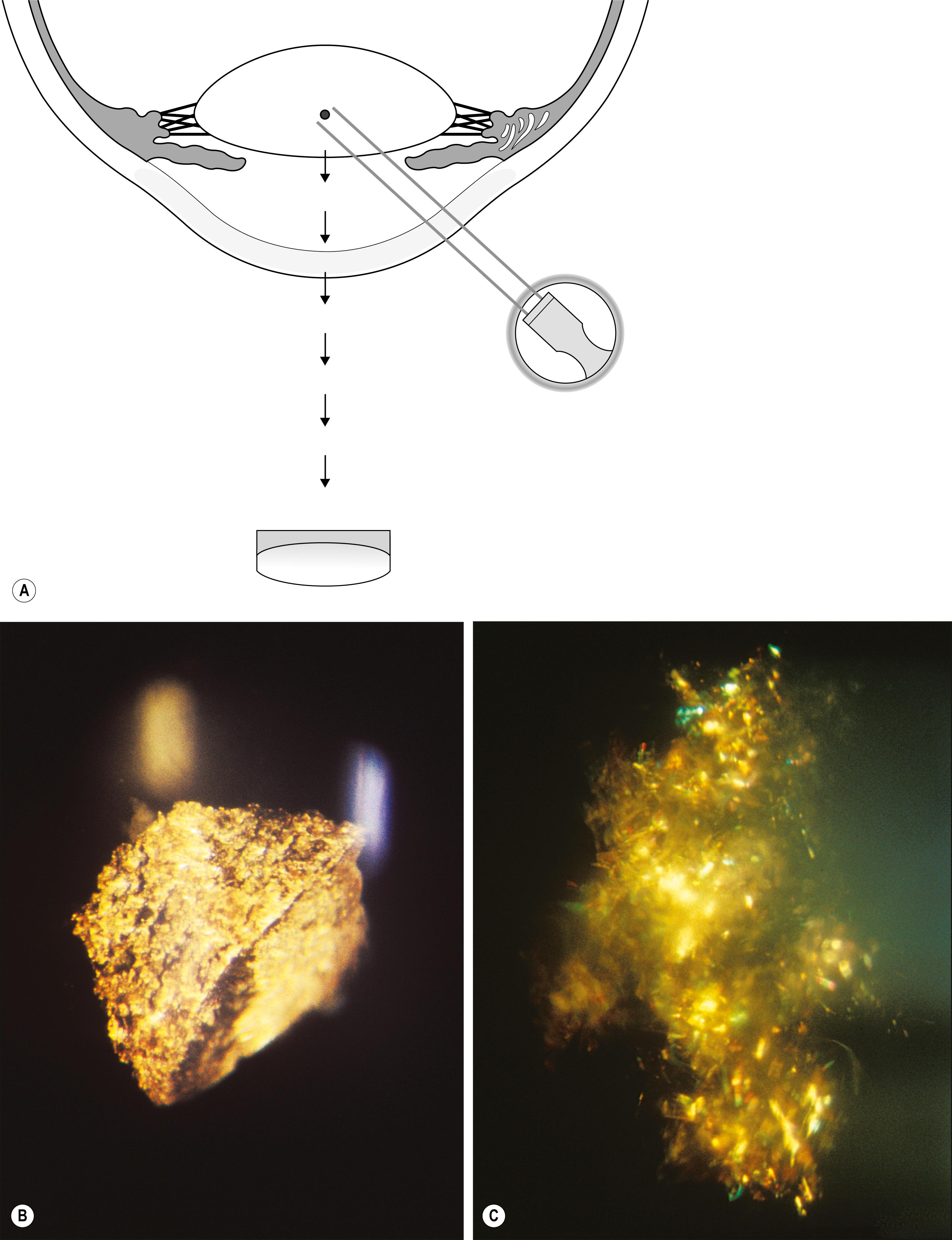
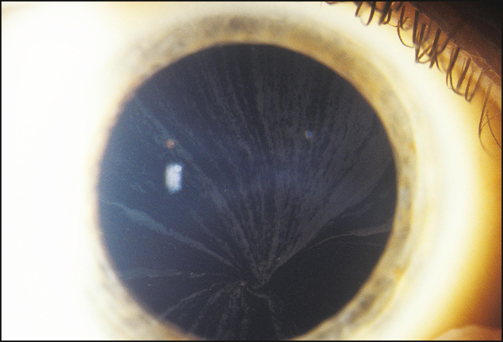
Using the light reflected by the retinal pigment epithelium, the anterior vitreous, lens, and cornea may be examined in retroillumination. The slit lamp illuminator is placed into an axial position with the biomicroscope, and the light is introduced through a dilated pupil to illuminate the fundus. With modest excursions of the illuminator to either side of center, the optimum position is established when the greatest retroillumination effect is achieved. A large pupil is required for maximum effectiveness. After configuring a moderately sized beam, the entire instrument can be moved from side to side to facilitate examination of most of the cornea. Decentering the slit to one side of the available pupil and then to the other facilitates a serial, uncompromised view of both sides of the subject stratum, and the area under study remains centered in the biomicroscope. Leaving the iris unilluminated ensures maximum visibility of the abnormality. Light striking the iris causes scatter and reduces the effectiveness of this valuable form of illumination.
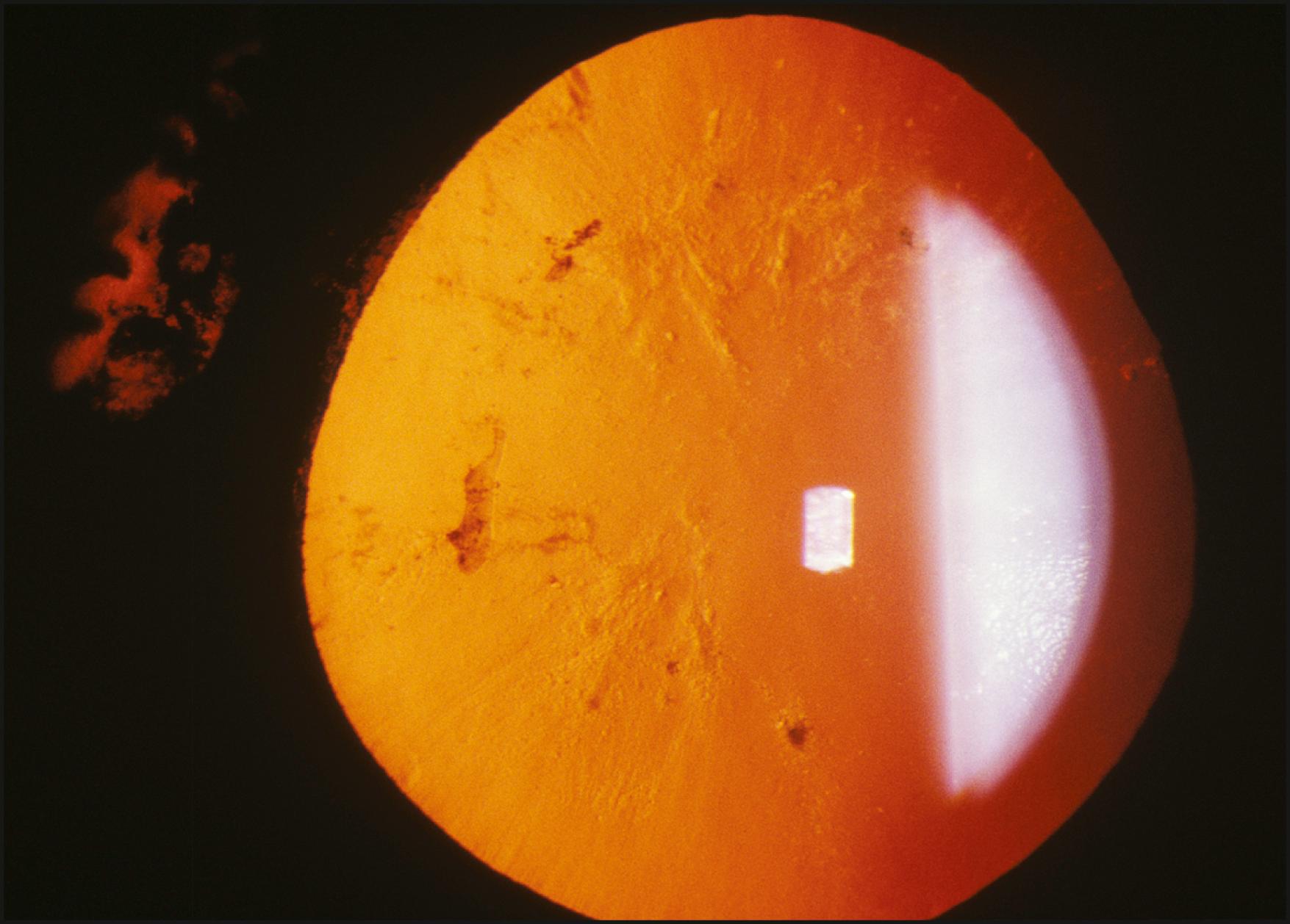
One major advantage of this modality is that it produces excellent delineation of subtle changes over a wide area of distribution. In that regard, it is similar to sclerotic scatter. The principal difference between the two is that sclerotic scatter produces dark-field illumination (objects illuminated against a dark background), whereas retroillumination from the fundus is a bright-field technique (objects silhouetted against a bright background). Dark-field illumination excels at demonstrating changes that primarily reflect light, and the bright-field technique produces best contrast for opaque changes and those that are refractile ( Box 7.6 ). Much of the cornea or lens may be visualized simultaneously, limited only by the size of the pupil and shallow depth of field. The classic findings in fingerprint dystrophy are beautifully displayed in this form of illumination ( Fig. 7.40 ). Similarly, many lens changes are most easily identified in this manner. Cataract formation and subluxation of the lens are dramatically demonstrated ( Fig. 7.41 ). The essentially colorless lens and cornea are transformed into structures seen in additional contrast by virtue of the color reflected by the retinal pigment epithelium.
Lattice dystrophy
Pseudoexfoliation
Keratic precipitates
Corneal scars
Meesmann dystrophy
Map-dot-fingerprint dystrophy
Lens vacuoles
Cataract
Corneal rejection lines
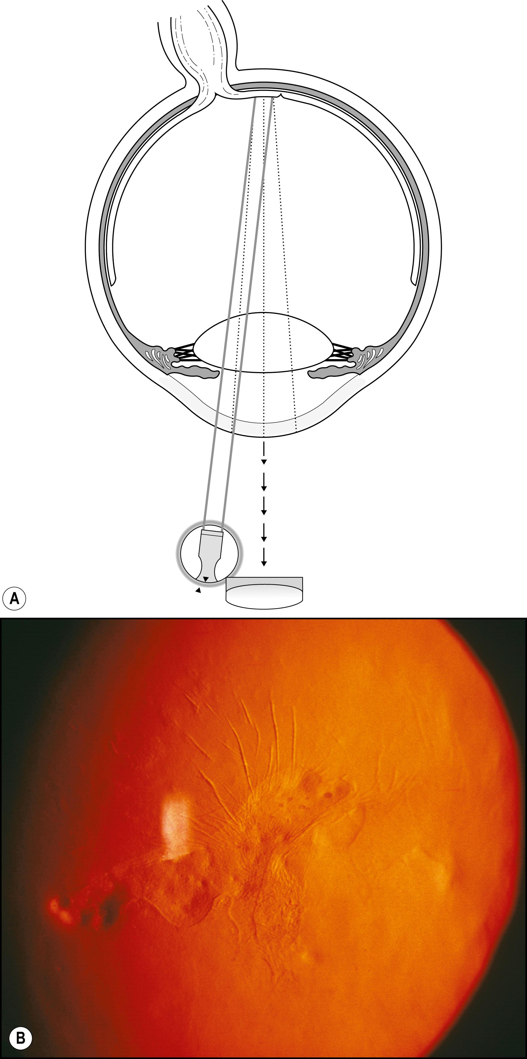
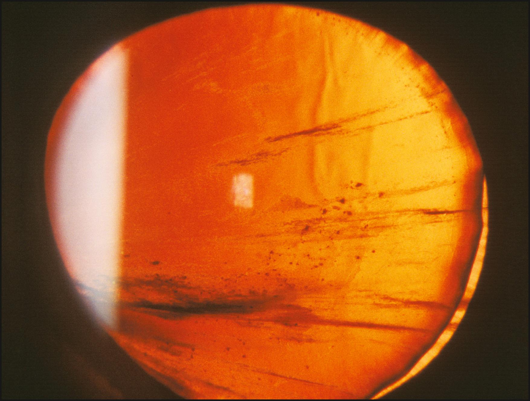
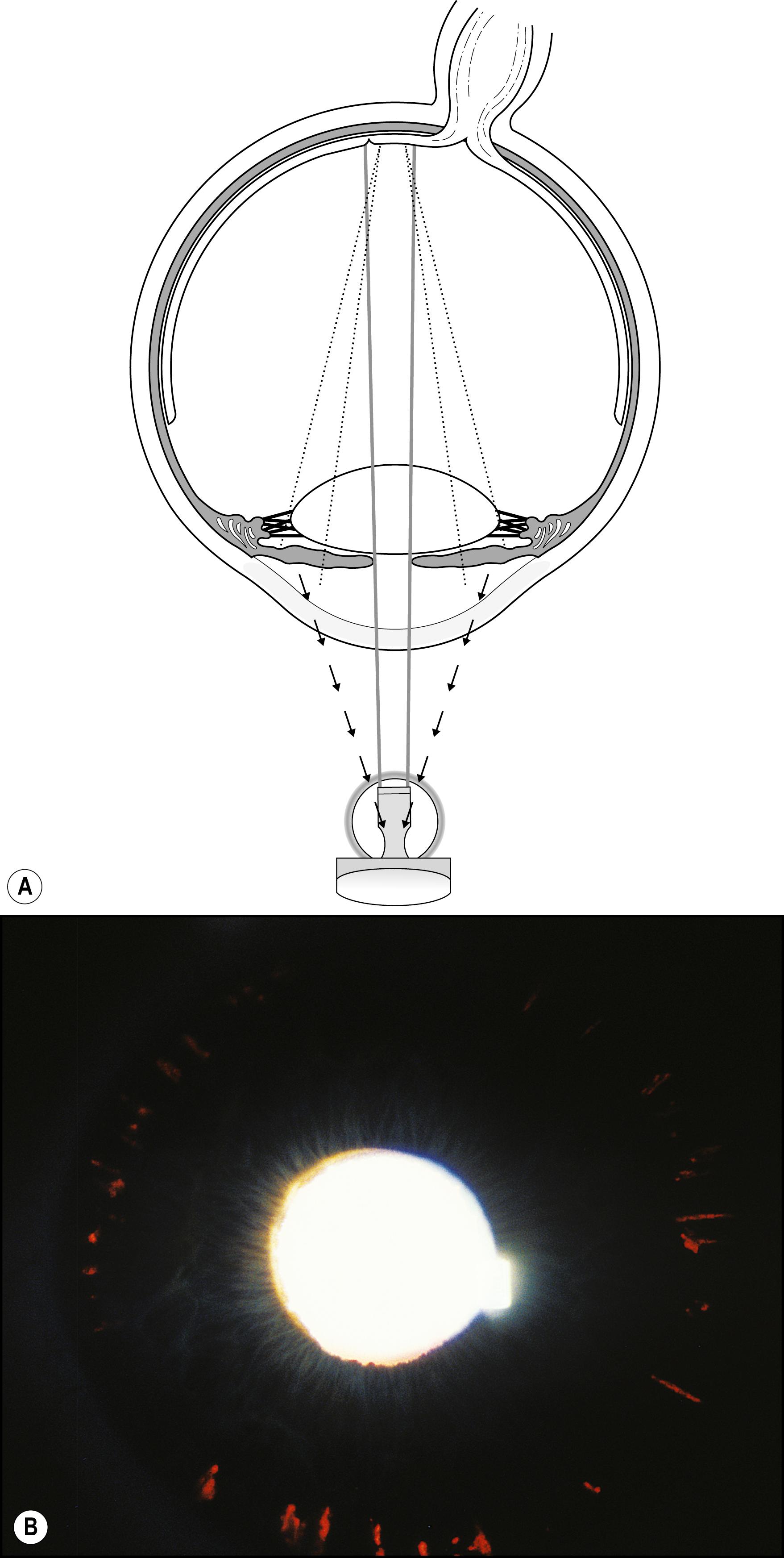
Iris transillumination is a simple extension of the technique just described ( Fig. 7.42 ). An important difference is the optimum pupil size. A completely dilated pupil is counterproductive to iris transillumination; a pupil size of 2–3 mm is ideal. Through such an opening, a moderate beam of high intensity can be introduced to illuminate the fundus. In that presentation, the iris is still sufficiently attenuated to demonstrate even subtle expressions of transillumination ( Fig. 7.43 ).
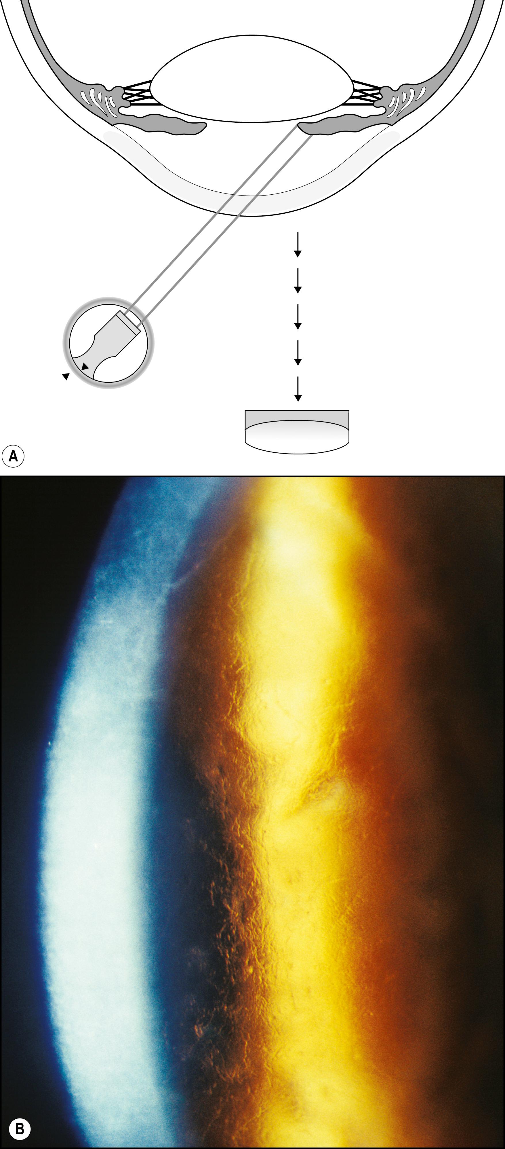
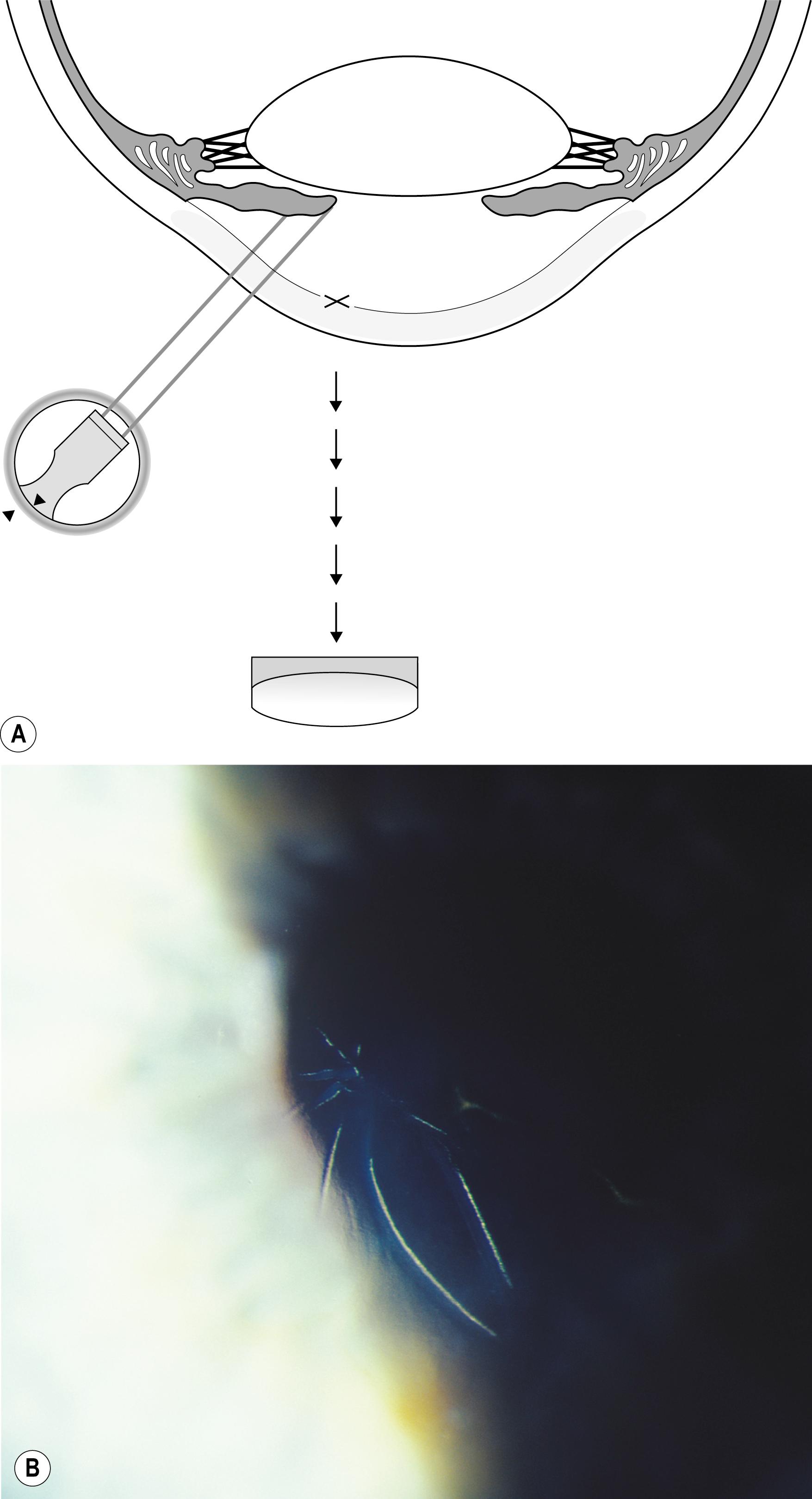
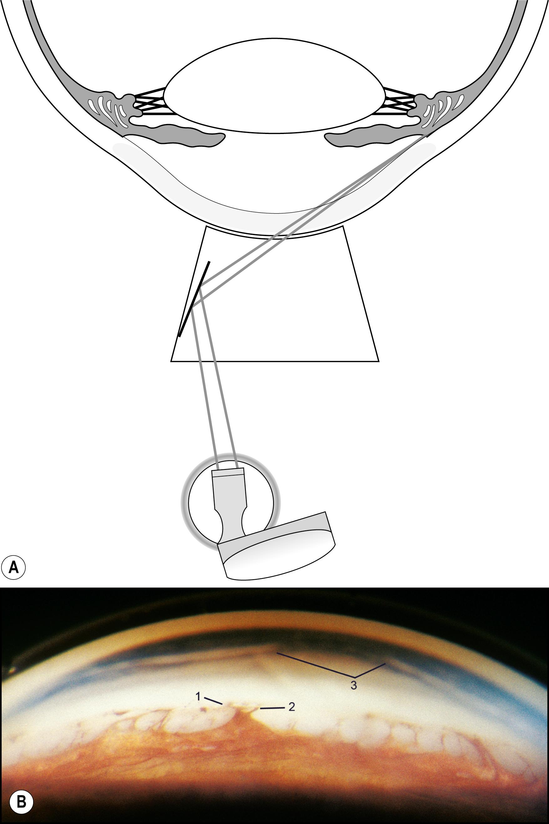
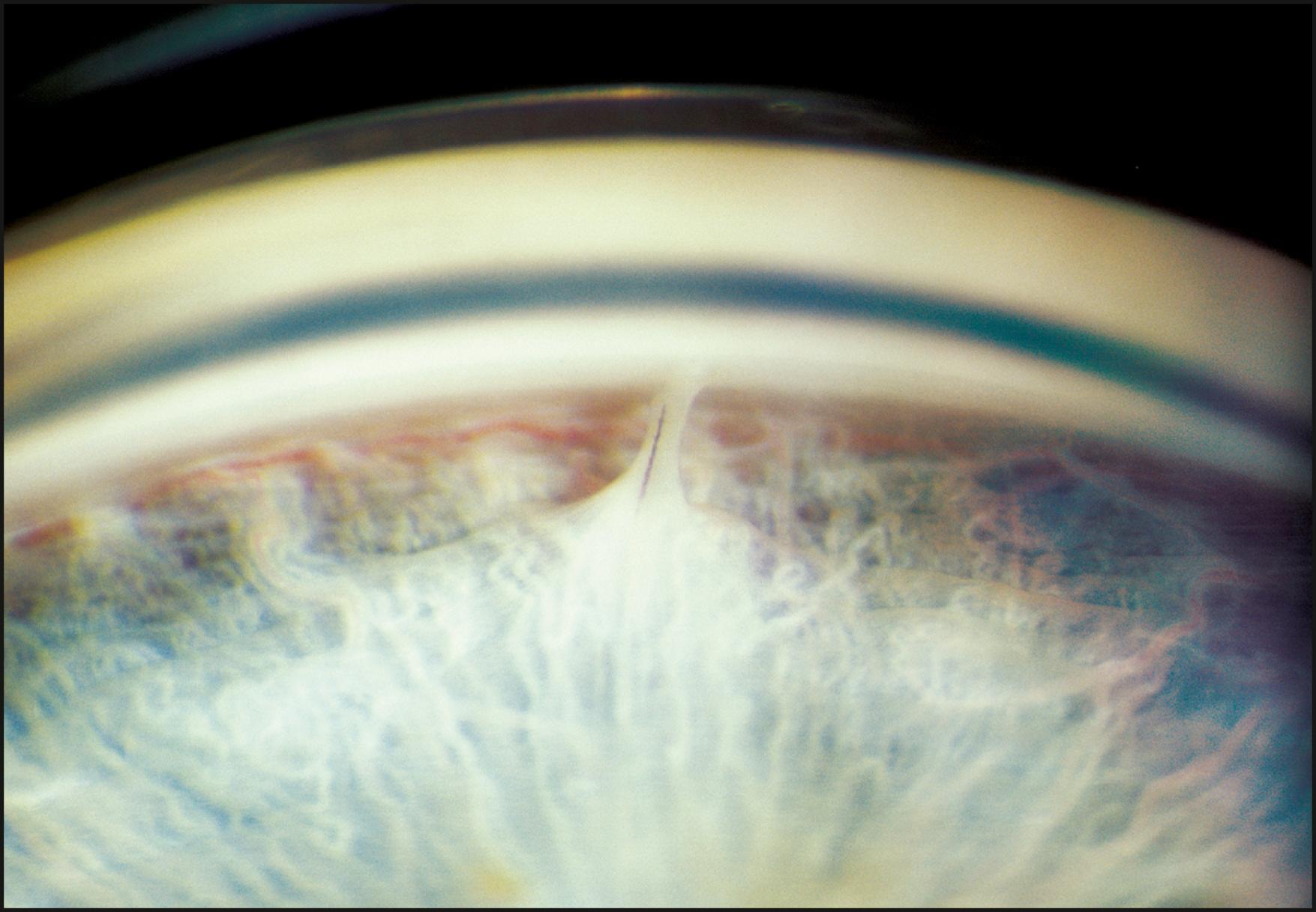
The peripheral cornea cannot be examined without the use of a gonioscope. Indirect lenses provide the ideal view with a choice of mirror angles and reduced light scatter. Once the lens is placed, the optical section can provide information regarding the posterior surface of the cornea and the condition of the angle. A wider beam, which is conformed to the area under study, is useful for the simultaneous view of a larger area to assess structural relationships further. Confining the beam to the zone of immediate attention minimizes distracting reflections that inevitably reduce contrast and detail ( Fig. 7.44 ). The anterior chamber angle is extremely reflective in most eyes, and moderate amounts of light are suggested for its examination ( Fig. 7.45 ).
Become a Clinical Tree membership for Full access and enjoy Unlimited articles
If you are a member. Log in here