Physical Address
304 North Cardinal St.
Dorchester Center, MA 02124
Total hip arthroplasty is the most commonly performed adult reconstructive hip procedure. This chapter discusses cemented and noncemented arthroplasties, bearing choices, and current trends in surgical approaches and less invasive techniques. In addition, revision hip arthroplasty, which comprises an enlarging segment of procedures performed, is reviewed.
The results of the Charnley total hip arthroplasty (THA) are the benchmark for evaluating the performance of other arthroplasties. The laboratory and clinical contributions of Charnley have improved the quality of life for many patients. Nevertheless, the history of hip arthroplasty has been dynamic, and research continues to improve results, especially in young patients. Investigation has proceeded along multiple paths, including (1) improvement in the durability of implant fixation, (2) reduction in the wear of the articulating surfaces, and (3) technical modifications in the operation to speed rehabilitation and reduce implant-positioning errors.
In response to the problem of loosening of the stem and cup based on the alleged failure of cement, press-fit, porous-coated, and hydroxyapatite-coated stems and cups have been investigated as ways to eliminate the use of cement and to use bone ingrowth or ongrowth as a means of achieving durable skeletal fixation. Although some initial cementless implant designs have proved very successful, others have been beset by premature and progressive failure because of inadequate initial fixation, excessive wear, and periprosthetic bone loss secondary to particle-induced osteolysis. As experience has accumulated, the importance of certain design parameters has become apparent and the use of cementless fixation for the femoral and acetabular components has become more common.
Many different techniques have evolved to improve cemented femoral fixation, including injection of low-viscosity cement, occlusion of the medullary canal, reduction of porosity, pressurization of the cement, and centralization of the stem. Similar techniques have been less successful in improving the results of acetabular fixation. Stem fracture has been largely eliminated by routine use of superalloys in their fabrication.
As technologic advances improve the longevity of implant fixation, problems related to wear of articulating surfaces have emerged. Highly crosslinked polyethylenes have demonstrated reduced wear and have now largely replaced conventional ultra-high-molecular-weight polyethylene. Ceramic-ceramic articulations have been used because of their low coefficient of friction and superior in vitro wear characteristics; these have also been successful. The initial enthusiasm for metal-on-metal articulations has been tempered by high failure rates caused by metal hypersensitivity reactions. The introduction of these more wear-resistant bearings has led to the use of larger component head sizes and modifications of postoperative regimens.
Consider the problems of previous materials and design modifications that did not become apparent until the results of a sufficient number of 5-year or more follow-up studies were available. There is little debate that the results of revision procedures are less satisfactory and that primary THA offers the best chance of success. Selection of the appropriate patient, the proper implants, and the technical performance of the operation are of paramount importance.
THA procedures require the surgeon to be familiar with the many technical details of the operation. To contend successfully with the many problems that occur and to evaluate new concepts and implants, a working knowledge of biomechanical principles, materials, and design also is necessary.
The biomechanics of THA are different from those of the screws, plates, and nails used in bone fixation because these latter implants provide only partial support and only until the bone unites. Total hip components must withstand many years of cyclic loading equal to at least three times body weight. A basic knowledge of the biomechanics of the hip and of THA is necessary to perform the procedure properly, to manage the problems that may arise during and after surgery successfully, to select the components intelligently, and to counsel patients concerning their physical activities.
To describe the forces acting on the hip joint, the body weight can be depicted as a load applied to a lever arm extending from the body’s center of gravity to the center of the femoral head ( Fig. 3.1 ). The abductor musculature, acting on a lever arm extending from the lateral aspect of the greater trochanter to the center of the femoral head, must exert an equal moment to hold the pelvis level when in a one-legged stance and a greater moment to tilt the pelvis to the same side when walking. Because the ratio of the length of the lever arm of the body weight to that of the abductor musculature is about 2.5:1, the force of the abductor muscles must approximate 2.5 times the body weight to maintain the pelvis level when standing on one leg. The estimated load on the femoral head in the stance phase of gait is equal to the sum of the forces created by the abductors and the body weight and has been calculated to be three times the body weight; the load on the femoral head during straight-leg raising is estimated to be about the same.
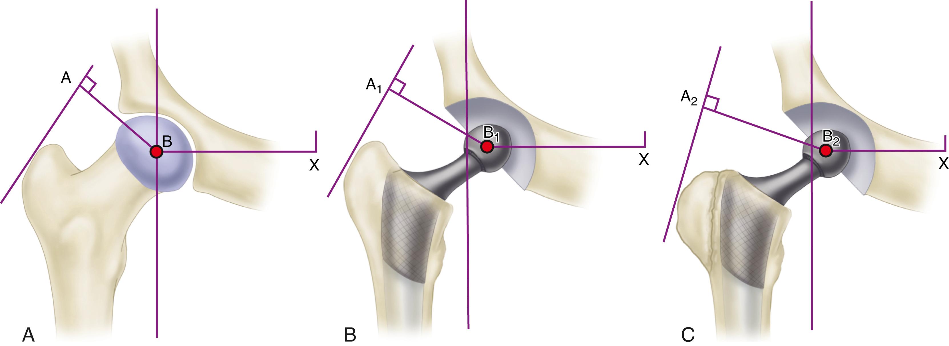
An integral part of the Charnley concept of THA was to shorten the lever arm of the body weight by deepening the acetabulum and to lengthen the lever arm of the abductor mechanism by reattaching the osteotomized greater trochanter laterally. The moment produced by the body weight is decreased, and the counterbalancing force that the abductor mechanism must exert is decreased. The abductor lever arm may be shortened in arthritis and other hip disorders in which part or all of the head is lost or the neck is shortened. It also is shortened when the trochanter is located posteriorly, as in external rotational deformities, and in many patients with developmental dysplasia of the hip. In an arthritic hip, the ratio of the lever arm of the body weight to that of the abductors may be 4:1. The lengths of the two lever arms can be surgically changed to make their ratio approach 1:1 (see Fig. 3.1 ). Theoretically, this reduces the total load on the hip by 30%. Femoral rotational alignment also plays a role in these changes in moment arms. In a finite element model, Terrier et al. found that changes in moment arms with cup medialization were inversely correlated with femoral anteversion, such that hips with less femoral anteversion gained more in terms of muscle moments.
Understanding the benefits derived from medializing the acetabulum and lengthening the abductor lever arm is important; however, neither technique is currently emphasized. The principle of medialization has given way to preserving subchondral bone in the pelvis and to deepening the acetabulum only as much as necessary to obtain bony coverage for the cup. Because most total hip procedures are now done without osteotomy of the greater trochanter, the abductor lever arm is altered only relative to the offset of the head to the stem. These compromises in the original biomechanical principles of THA have evolved to obtain beneficial tradeoffs of a biologic nature; to preserve pelvic bone, especially subchondral bone; and to avoid problems related to reattachment of the greater trochanter.
Calculated peak contact forces across the hip joint during gait range from 3.5 to 5.0 times the body weight and up to six times the body weight during single-limb stance. Experimentally measured forces around the hip joint using instrumented prostheses generally are lower than the forces predicted by analytical models, in the range of 2.6 to 3.0 times the body weight during single-limb stance phase of gait. When lifting, running, or jumping, however, the load may be equivalent to 10 times the body weight. Excess body weight and increased physical activity add significantly to the forces that act to loosen, bend, or break the femoral component.
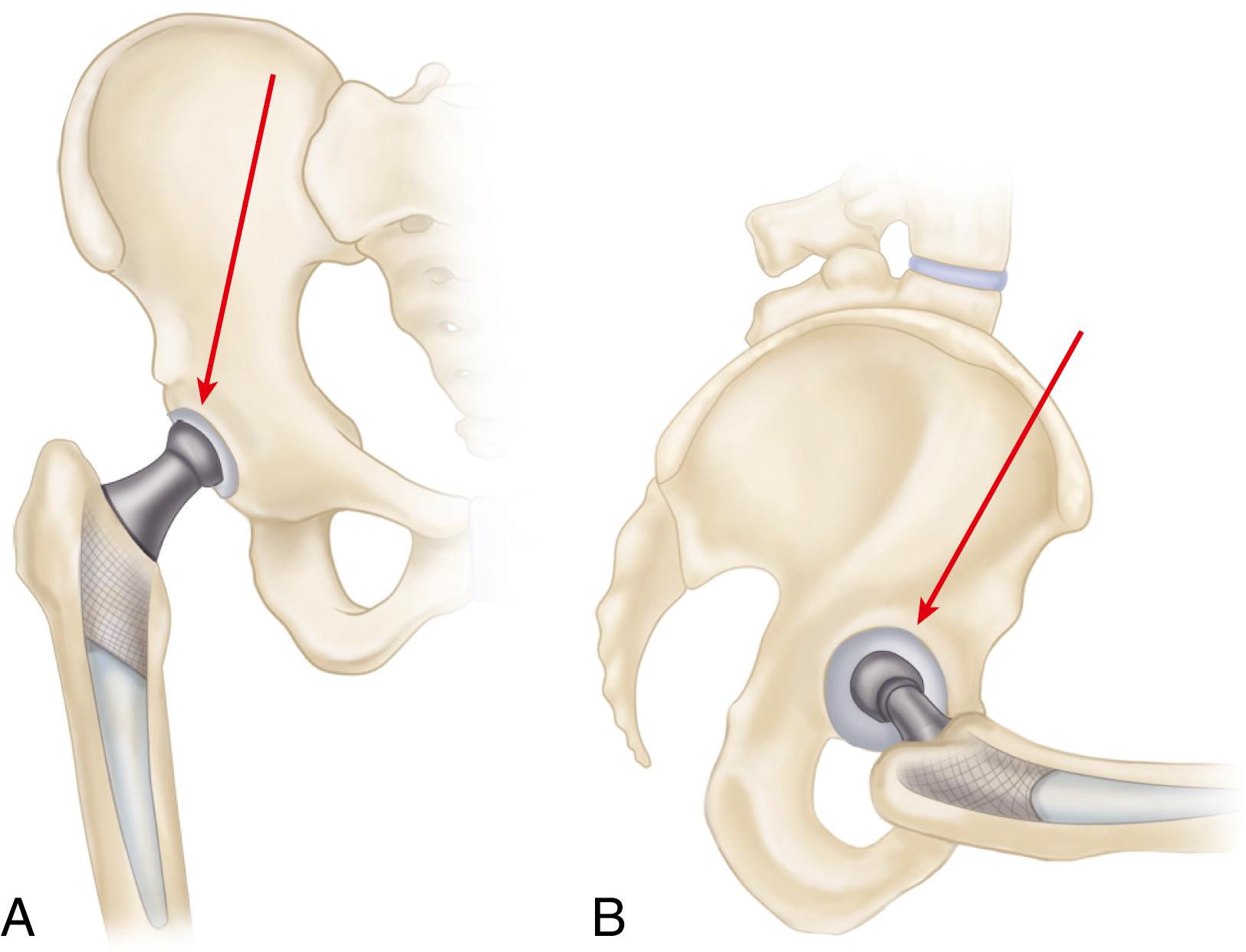
The forces on the joint act not only in the coronal plane but, because the body’s center of gravity (in the midline anterior to the second sacral vertebral body) is posterior to the axis of the joint, also in the sagittal plane to bend the stem posteriorly. The forces acting in this direction are increased when the loaded hip is flexed, as when arising from a chair, ascending and descending stairs or an incline, or lifting ( Fig. 3.2 ). During the gait cycle, forces are directed against the prosthetic femoral head from a polar angle between 15 and 25 degrees anterior to the sagittal plane of the prosthesis. During stair climbing and straight-leg raising, the resultant force is applied at a point even farther anterior on the head. Such forces cause posterior deflection or retroversion of the femoral component. These so-called out-of-plane forces have been measured at 0.6 to 0.9 times body weight.
Implanted femoral components must withstand substantial torsional forces even in the early postoperative period. Consequently, femoral components used without cement must be designed and implanted so that they are immediately rotationally stable within the femur. Similarly, the shape of a cemented implant must impart rotational stability within its cement mantle.
The location of the center of rotation of the hip from superior to inferior also affects the forces generated around the implant. In a mathematical model, the joint reaction force was lower when the hip center was placed in the anatomic location compared with a superior and lateral or posterior position. Isolated superior displacement without lateralization produces relatively small increases in stresses in the periacetabular bone. This has clinical importance in the treatment of developmental dysplasia and in revision surgery when superior bone stock is deficient. Placement of the acetabular component in a slightly cephalad position allows improved coverage or contact with viable bone. Nonetheless, clinical studies have documented a higher incidence of progressive radiolucencies and migration of components in patients with protrusion, dysplasia, and revision situations when the hip center was placed in a nonanatomic position.
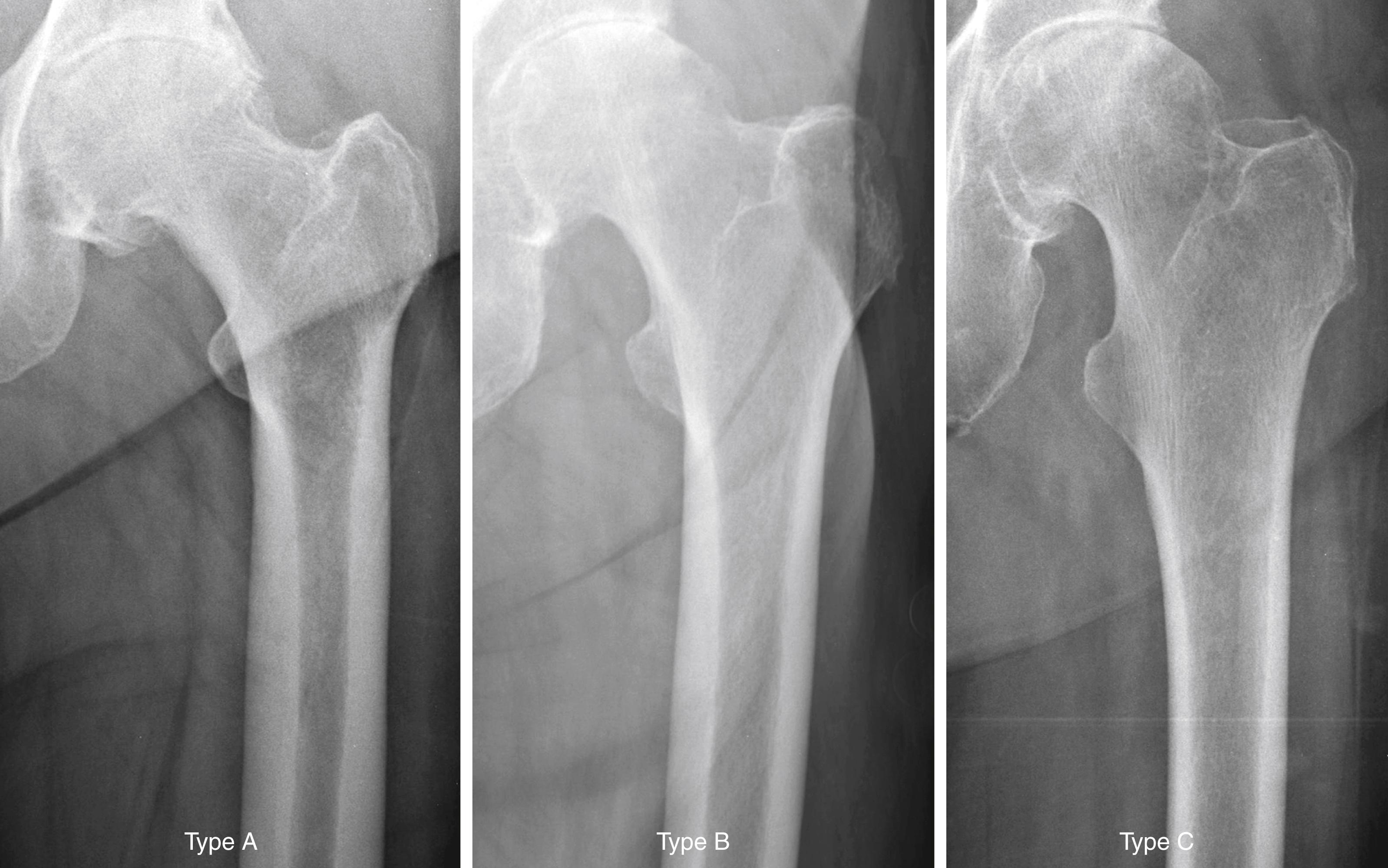
The quality of the bone before surgery is a determinant in the selection of the most appropriate implant, optimal method of fixation, response of the bone to the implant, and ultimate success of the arthroplasty. Dorr et al. proposed a radiographic categorization of proximal femurs based on their shape and correlated those shapes with measurements of cortical thickness and canal dimensions ( Fig. 3.3 ). Type A femurs have thick cortices on the anteroposterior view and a large posterior cortex seen on the lateral view. The narrow distal canal gives the proximal femur a pronounced funnel shape or “champagne flute” appearance. The type A femur is more commonly found in men and younger patients and permits good fixation of either cemented or cementless stems. Type B femurs exhibit bone loss from the medial and posterior cortices, resulting in increased width of the intramedullary canal. The shape of the femur is not compromised, and implant fixation is not a problem. Type C femurs have lost much of the medial and posterior cortex. The intramedullary canal diameter is very wide, particularly on the lateral radiograph. The “stovepipe”-shaped type C bone is typically found in older postmenopausal women and creates a less favorable environment for cementless implant fixation.
The material a stem is made of, the geometry, length, and size of the stem, and the method and extent of fixation dramatically alter the pattern in which stress is transferred to the femur. Adaptive bone remodeling arising from stress shielding compromises implant support and predisposes to fracture of the femur or the implant itself. Stress transfer to the femur is desirable because it provides a physiologic stimulus for maintaining bone mass and preventing disuse osteoporosis. A decrease in the modulus of elasticity of a stem decreases the stress in the stem and increases stresses to the surrounding bone. This is true of stems made of metals with a lower modulus of elasticity, such as a titanium alloy, particularly if the cross-sectional diameter is relatively small. Larger-diameter stems made of the same material are stronger, but they also are stiffer or less elastic, and the increased cross-sectional diameter negates any real benefits of the lower modulus of elasticity. The bending stiffness of a stem is proportional to the fourth power of the diameter, and small increases in stem diameter produce much larger increments of change in flexural rigidity. When the stem has been fixed within the femur by bone ingrowth, load is preferentially borne by the stiffer structure and the bone of the proximal femur is relieved of stress.
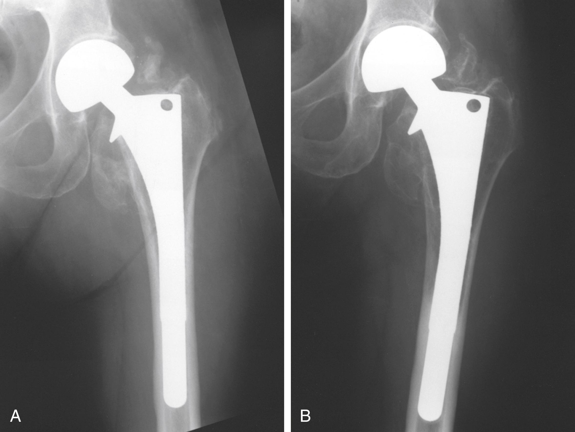
Detailed examinations of stress shielding of the femur after cementless total hip replacement found that almost all femurs showing moderate or severe proximal resorption involved stems 13.5 mm in diameter or larger. With a press-fit at the isthmus and radiographic evidence of bone ingrowth, more stress shielding was evident. Extensive porous coating in smaller size stems does not seem to produce severe stress shielding. More recent follow-up with larger stem sizes shows greater stress shielding, however, with more extensively coated stems ( Fig. 3.4 ). Localized bone hypertrophy can be seen in areas where an extensively porous-coated stem contacts the cortex. This is seen often at the distal end of the porous coating with an extensively coated stem. Such hypertrophy is less pronounced when the porous surface is confined to the proximal portion of the stem. In a meta-analysis of studies of femoral bone loss, Knutsen et al. found that cementless stems had more proximal bone loss than cemented implants and cobalt-chromium stems had nearly double the proximal bone loss seen with titanium alloy femoral stems.
Videodensitometry analysis of autopsy-retrieved femurs found that for cemented and cementless implants, the area of greatest decrease in bone mineral density occurred in the proximal medial cortex. Dual energy x-ray absorptiometry scans show bone loss in the proximal femur progresses over a period of at least 5 years after surgery. This loss of mineral density does not occur with resurfacing arthroplasty. Shorter length stem designs also aim to load the proximal femoral bone in a more physiological manner to reduce bone loss in this area.
If a prosthesis has a collar that is seated on the cut surface of the neck, it is postulated that axial loading of the bone would occur in this area. It is technically difficult, however, to obtain this direct contact of a collar or cement with the cut surface of bone. Although the role of a collar in preventing loosening of a cemented femoral component has not been clearly established, any loading of the proximal medial neck is likely to decrease bone resorption and reduce stresses in the proximal cement. The presence of a collar on cementless femoral components is more controversial because it may prevent complete seating of the stem, making it loose at implantation.
Cementless stems generally produce strains in the bone that are more physiologic than the strains caused by fully cemented stems, depending on the stem size and the extent of porous coating. Proximal medial bone strains have been found to be 65% of normal with a collarless press-fit stem and 70% to 90% with a collared stem with an exact proximal fit. A loose-fitted stem with a collar can produce proximal strains greater than in the intact femur, although the consequences of a loose stem negate any potential benefits in loading provided by the collar. When a stem is loaded, it produces circumferential or hoop stresses in the proximal femur. Proximal wedging of a collarless implant may generate excessive hoop strains that cause intraoperative and postoperative fractures of the proximal femur. Prophylactic cerclage wire placement increases energy to failure and may reduce the risk of periprosthetic fracture, particularly when the femur is osteopenic or bony defects are present.
Stem shape also seems to affect stress transfer to bone. In a review of three different types of titanium stems with tapered geometries, an overall incidence of radiographic proximal femoral bone atrophy of only 6% was found in the 748 arthroplasties studied. In no patient was the proximal bone loss as severe as that seen in patients with stems of a cylindrical distal geometry that filled the diaphysis.
Cadaver studies have identified a wide variability in the degree and location of bone remodeling between individuals in clinically successful arthroplasties with solid fixation. A strong correlation was shown, however, between the bone mineral density in the opposite femur and the percentage of mineral loss in the femur that had been operated on, regardless of the method of implant fixation; it seems that patients with diminished bone mineral density before surgery are at greatest risk for significant additional bone loss after cemented and cementless THA.
The amount of stress shielding that is acceptable in the clinical setting is difficult to determine. In a series of 208 hip arthroplasties followed for a mean 13.9 years, Engh et al. reported patients with radiographically evident stress shielding had lower mean walking scores but no increase in other complications and were less likely to require revision for stem loosening or osteolysis. Although proximal femoral stress shielding does not seem to affect adversely early or midterm clinical results, experience with failed cemented implants has also shown that revision surgery becomes more complex when femoral bone stock has been lost. Ongoing investigations into materials and stem design are likely to be beneficial in reducing adverse femoral remodeling.
On the pelvic side, finite analysis has indicated that with the use of a cemented polyethylene cup, peak stresses develop in the pelvic bone. A metal-backed cup with a polyethylene liner reduces the high areas of stress and distributes the stresses more evenly. Similar studies have indicated that increased peak stresses develop in the trabecular bone when the subchondral bone is removed and that decreased peak stresses develop when a metal-backed component is used. The highest stresses in the cement and trabecular bone develop when a thin-walled, polyethylene acetabular component is used and when the subchondral bone has been removed. Stress on the cement-bone interface may also be increased up to 9% when a larger diameter femoral head is utilized. A thick-walled polyethylene cup of 5 mm or more, as opposed to a thin-walled polyethylene cup, tends to reduce the stresses in the trabecular bone, similar to the effect of the metal-backed cup. The preservation of subchondral bone in the acetabulum and the use of a metal-backed cup or thick-walled polyethylene cup decrease the peak stress levels in the trabecular bone of the pelvis.
Favorable early results with metal-backed, cemented acetabular components led to their widespread use in the past. Longer follow-up has shown no sustained benefit, however, from the use of metal backing, and in some series survivorship of the cemented metal-backed acetabular components has been worse than that of components without metal backing. Using a thick-walled, all-polyethylene component and retaining the subchondral bone of the acetabulum are two steps that seem to provide a satisfactory compromise without excessive stress shielding or stress concentration.
When cementless acetabular fixation is used, metal backing is required for skeletal fixation. Ideally, the metal should contact acetabular subchondral bone over a wide area to prevent stress concentration and to maximize the surface area available for biologic fixation. The accuracy of acetabular preparation and the shape and size of the implant relative to the prepared cavity dramatically affect this initial area of contact and the transfer of stress from the implant to the pelvis. If a hemispherical component is slightly undersized relative to the acetabulum, stress is transferred centrally over the pole of the component, with the potential for peripheral gaps between the implant and bone. Conversely, if the component is slightly larger than the prepared cavity, stress transfer occurs peripherally, with the potential for fracture of the acetabular rim during implantation (see section on implantation of cementless acetabular components). Polar gaps also may remain from incomplete seating of the component.
The manner of stress transfer from a cementless acetabular component to the surrounding acetabular bone dictates its initial stability. As the cup is impacted into the acetabulum, forces generated by elastic recoil of the bone stabilize the implant. Peripheral strains acting on a force vector perpendicular to the tangent at the rim stabilize the cup. Strains medial to the rim generate a force vector that pushes laterally and destabilizes the cup ( Fig. 3.5 ).
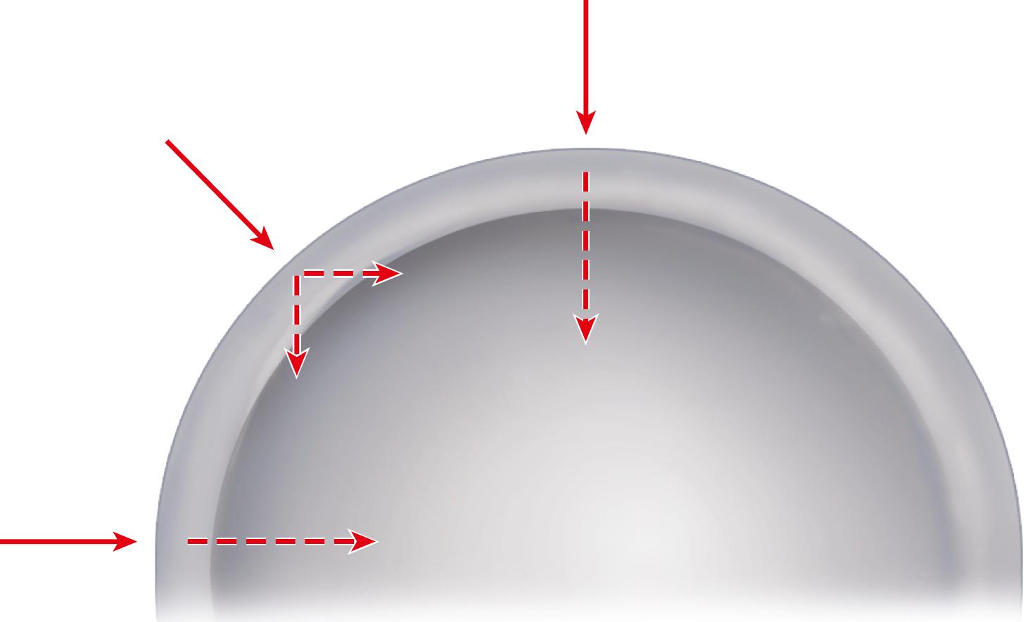
Stress shielding of the periacetabular bone by cementless implants has received less attention than with femoral components but does occur. Using a novel method of CT-assisted osteodensitometry, Mueller et al. assessed bone density around cementless titanium acetabular components at 10 days and 1 year postoperatively. Cortical bone density cephalad to the implant increased by 3.6%. Conversely, cancellous bone density decreased by 18%, with the area of greatest loss anterior to the cup. The clinical importance of acetabular stress shielding has not been determined.
Total hip femoral and acetabular components of various materials and a multitude of designs are currently available. Few implant designs prove to be clearly superior or inferior to others. Certain design features of a given implant may provide an advantage in selected situations. Properly selected and implanted total hip components of most designs can be expected to yield satisfactory results in a high percentage of patients. No implant design or system is appropriate for every patient, and a general knowledge of the variety of component designs and their strengths and weaknesses is an asset to the surgeon. Selection is based on the patient’s needs, the patient’s anticipated longevity and level of activity, the bone quality and dimensions, the ready availability of implants and proper instrumentation, and the experience of the surgeon.
We routinely use many total hip systems from different manufacturers; we present here an overview of the available systems, emphasizing similar and unique features. Numerous investigators and manufacturers have changed their designs within a relatively short time to incorporate newer concepts, and this confuses many orthopaedic surgeons and patients. The surgeon’s recommendations should be tempered by the knowledge that change does not always bring about improvement and that radical departure from proven concepts of implant design yields unpredictable long-term results.
Total hip femoral and acetabular components are commonly marketed together as a total hip system. While the practice is off-label, the variety of modular head sizes with most femoral components allows use with other types of acetabular components if necessary. Femoral and acetabular components are discussed separately.
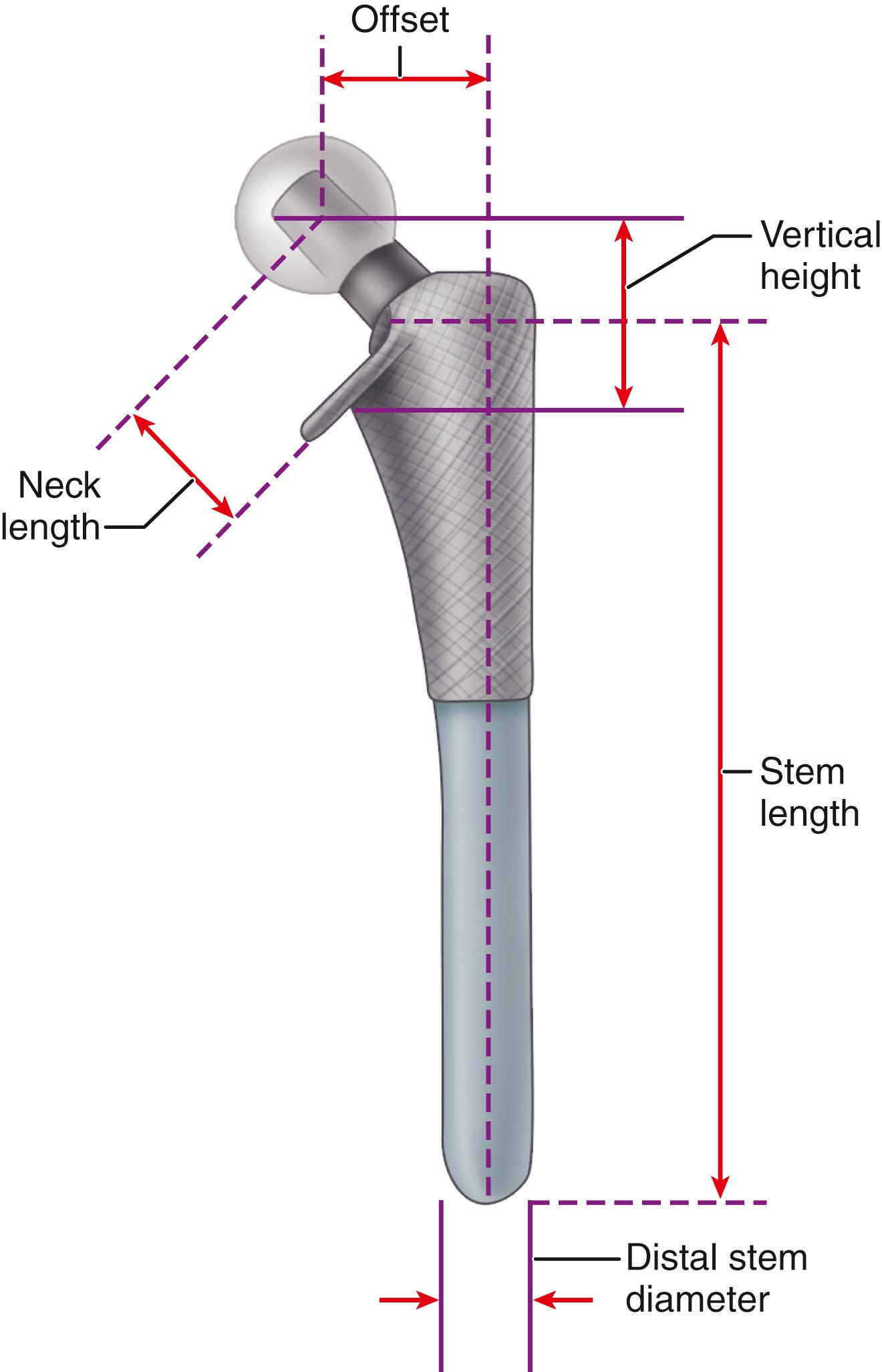
The primary function of the femoral component is the replacement of the femoral head and neck after resection of the arthritic or necrotic segment. The ultimate goal of a biomechanically sound, stable hip joint is accomplished by careful attention to restoration of the normal center of rotation of the femoral head. This location is determined by three factors: (1) vertical height (vertical offset), (2) medial offset (horizontal offset or, simply, offset), and (3) version of the femoral neck (anterior offset) ( Fig. 3.6 ). Vertical height and offset increase as the neck is lengthened, and proper reconstruction of both features is the goal when selecting the length of the femoral neck.
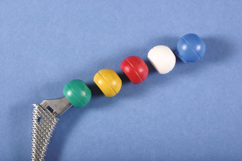
In most modern systems, neck length is adjusted by using modular heads with variable internal bores that mate with a uniformly tapered trunnion on the femoral component ( Fig. 3.7 ). The taper is commonly referred to as a Morse taper, although there is no defined standard across all manufacturers. A Morse taper is approximately 3 degrees on each side and the size is typically designated by the diameters at the upper and lower ends. The most common taper used presently is 12 mm/14 mm, but this has varied over time even within the implant offerings of a given manufacturer. It should also be noted that each manufacturer has unique specifications for their tapers and they vary by diameter at the smaller and larger ends, length, taper angle, and surface finish. Consequently, femoral heads from one manufacturer are not compatible with femoral trunnions of another even if the nominal size is the same. Toggling of the head on the trunnion, dissociation, material loss, and corrosion may result from such a mismatch.
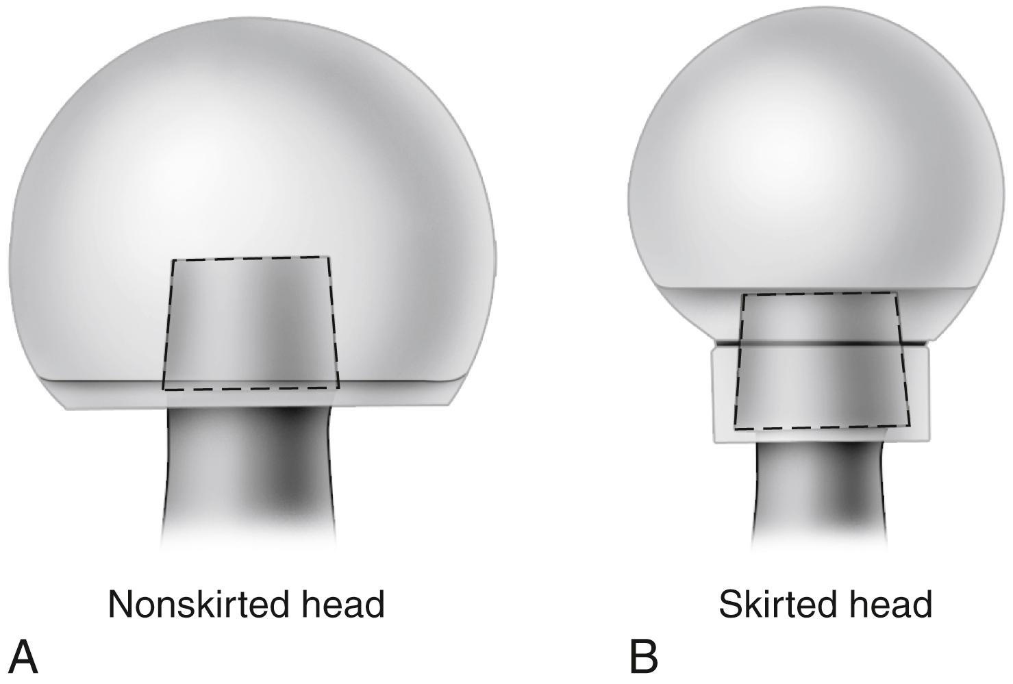
Neck length typically ranges from 25 to 50 mm, and adjustment of 8 to 12 mm for a given stem size routinely is available. When a long neck length is required for a head diameter up to 32 mm, a skirt extending from the lower aspect of the head may be required to fully engage the Morse taper ( Fig. 3.8 ). For heads larger than 32 mm a skirt is unnecessary even for longer neck lengths.
Vertical height (vertical offset) is determined primarily by the base length of the prosthetic neck plus the length gained by the modular head used. In addition, the depth the implant is inserted into the femoral canal alters vertical height. When cement is used, the vertical height can be adjusted further by variation in the level of the femoral neck osteotomy. This additional flexibility may be unavailable when a cementless femoral component is used because depth of insertion is determined more by the fit within the femoral metaphysis than by the level of the neck osteotomy.
Offset (i.e., horizontal offset) is the distance from the center of the femoral head to a line through the axis of the distal part of the stem and is primarily a function of stem design. Inadequate restoration of offset shortens the moment arm of the abductor musculature and results in increased joint reaction force, limp, and bone impingement, which may result in dislocation. Offset can be increased by simply using a longer modular neck, but doing so also increases vertical height, which may result in overlengthening of the limb. To address individual variations in femoral anatomy, many components are now manufactured with standard and high offset versions. This is accomplished by reducing the neck-stem angle (typically to about 127 degrees) or by attaching the neck to the stem in a more medial position ( Fig. 3.9 ). Reduction of the neck-stem angle increases offset but also reduces vertical height slightly. When the neck is attached in a more medial position, offset is increased without changing height; leg length is therefore unaffected.
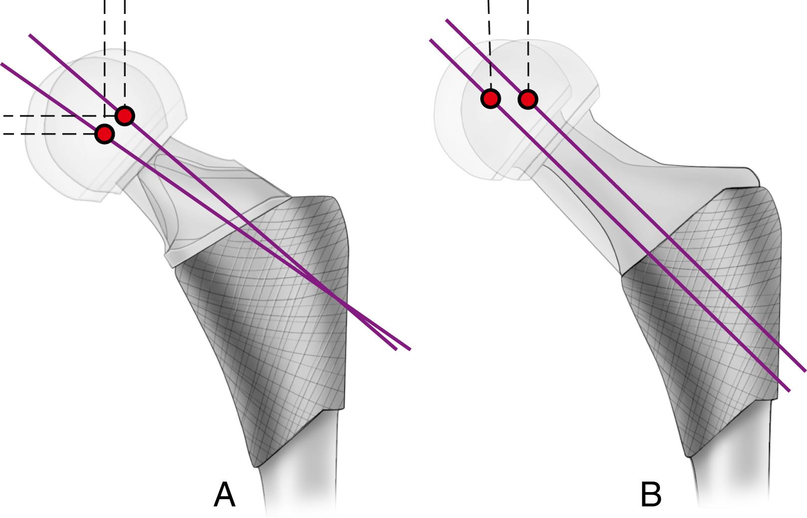
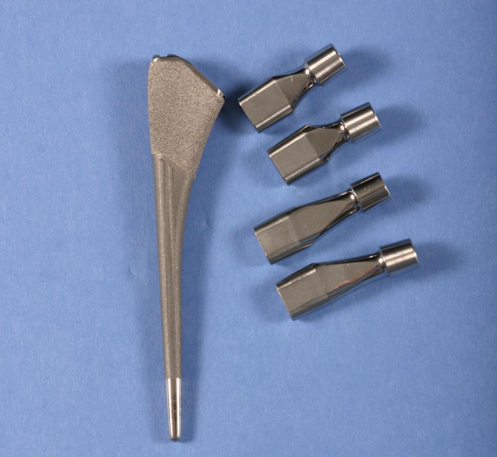
Version refers to the orientation of the neck in reference to the coronal plane and is denoted as anteversion or retroversion. Restoration of femoral neck version is important in achieving stability of the prosthetic joint. The normal femur has 10 to 15 degrees of anteversion of the femoral neck in relation to the coronal plane when the foot faces straight forward, and the prosthetic femoral neck should approximate this. Proper neck version usually is accomplished by rotating the component within the femoral canal. This presents little problem when cement is used for fixation; however, when press-fit fixation is used, the femoral component must be inserted in the same orientation as the femoral neck to maximize the fill of the proximal femur and achieve rotational stability of the implant. This problem can be circumvented by the use of a modular femoral component in which the stem is rotated independent of the metaphyseal portion. So-called anatomic stems have a slight proximal posterior bow to reproduce the contour of the femoral endosteum, predetermining the rotational alignment of the implant. Most such stems have a few degrees of anteversion built into the neck to compensate for this, and separate right and left stems are required. Finally, femoral components have been produced with dual modular necks in different geometries and lengths to allow the adjustment of length, offset, and version independently ( Fig. 3.10 ). However, tribocorrosion at the taper junction between the neck and stem has been reported with these dual modular necks, and several of the designs have been either recalled or voluntarily withdrawn from the market. Consequently, their use has declined markedly over the past few years.
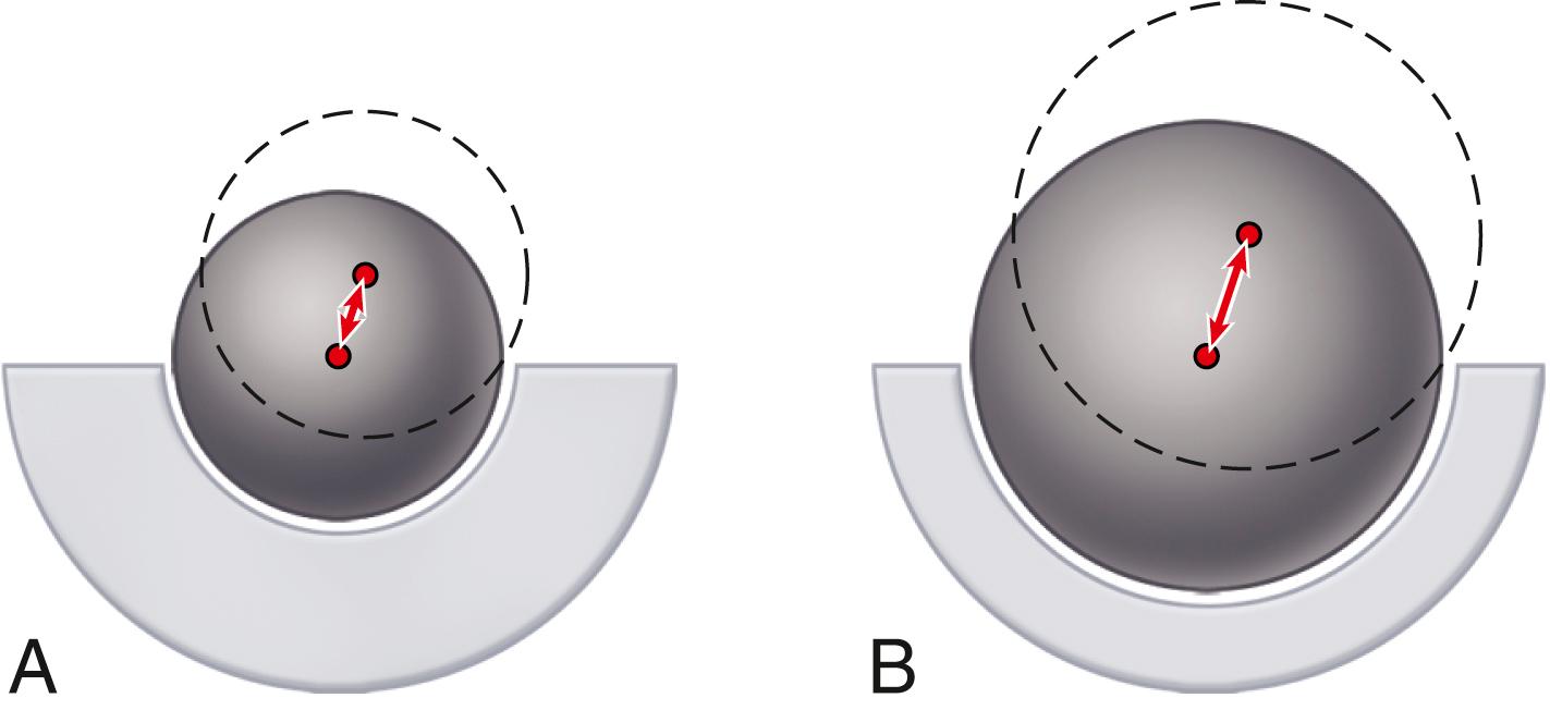
The size of the femoral head, the ratio of head and neck diameters, and the shape of the neck of the femoral component have a substantial effect on the range of motion of the hip, the degree of impingement between the neck and rim of the socket, and the stability of the articulation. This impingement can lead to dislocation, accelerated polyethylene wear, acetabular component loosening, and liner dislodgment or fracture. For a given neck diameter, the use of a larger femoral head increases the head-neck ratio and the range of motion before the neck impinges on the rim of the socket will be greater ( Fig. 3.11 ). When this impingement does occur, the femoral head is levered out of the socket. The “jump distance” is the distance the head must travel to escape the rim of the socket and is generally approximated to be half the diameter of the head ( Fig. 3.12 ). For both of these reasons, a larger-diameter head is theoretically more stable than a smaller one. In a large series of total hips performed with a head size of 36 mm or larger, Lombardi et al. reported a dislocation rate of only 0.05%. The introduction of advanced bearing surfaces has allowed the use of larger head sizes than those traditionally used in the past. In practical terms, the femoral head diameter is limited by the size of the acetabulum, regardless of the bearing materials used for the femoral head and acetabulum.
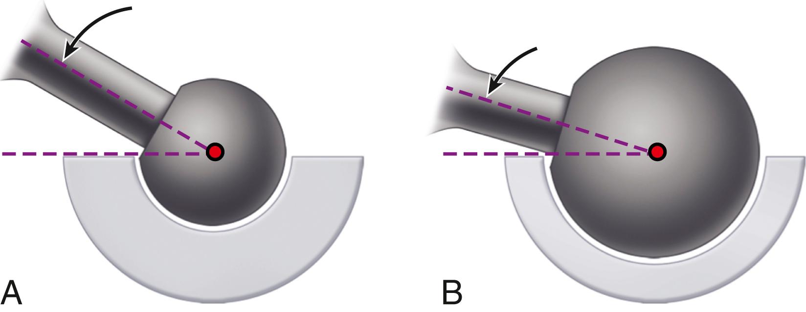
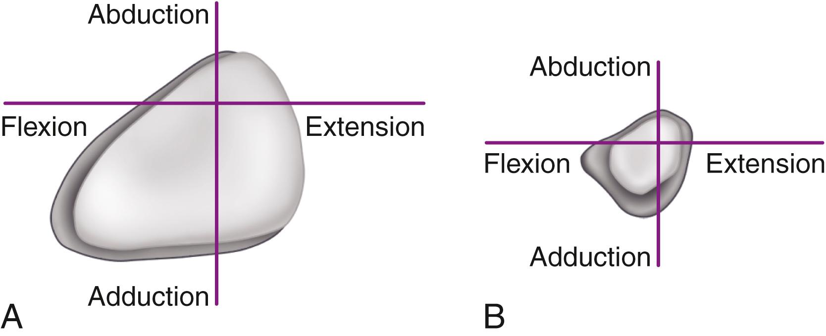
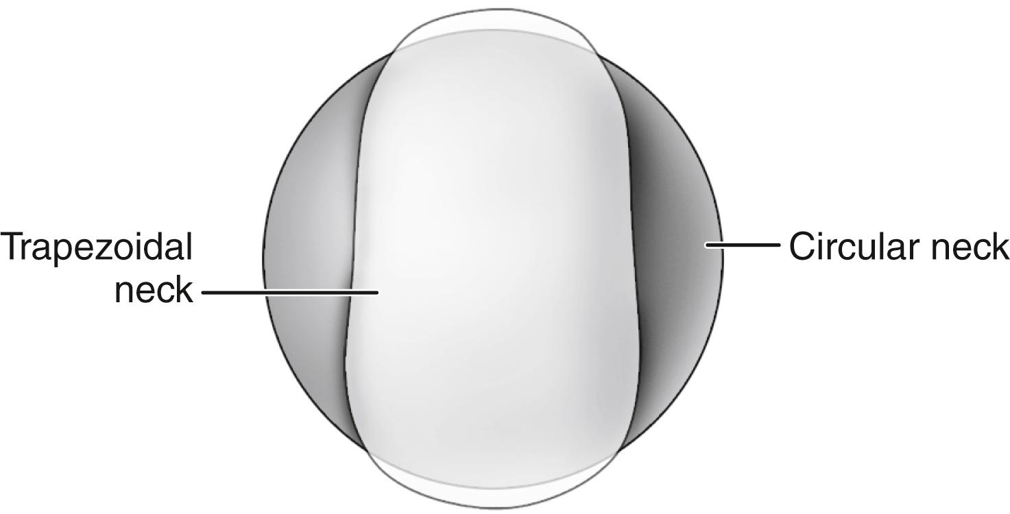
In a range-of-motion simulation with digitized implants and virtual reality software, Barrack et al. found an improvement of 8 degrees of hip flexion when head size was increased from 28 to 32 mm. Range of motion was dramatically reduced by the use of a circular neck, especially when combined with a skirted modular head, which increases the diameter of the femoral neck ( Fig. 3.13 ). A trapezoidal neck yielded greater range of motion without impingement than a circular one ( Fig. 3.14 ). In an experimental range-of-motion model with head sizes larger than 32 mm, Burroughs et al. found that impingement between prosthetic components could be largely eliminated. When a head size larger than 38 mm was used, however, the only impingement was bone on bone and was dependent on bony anatomy and independent of head size. The ideal configuration of the prosthetic head and neck segment includes a trapezoidal neck and a larger diameter head without a skirt.
All total hip systems in current use achieve fixation of the femoral prosthesis with a metal stem that is inserted into the medullary canal. Much of the design innovation to increase prosthetic longevity has been directed toward improvement in fixation of the implant within the femoral canal. Many femoral stems have been in clinical use for variable periods since the 1990s. Recognition of the radiographic profile of a stem is often beneficial, however, in planning revision surgery. Readers are directed to previous editions of this text and other historical references for this information.
Femoral components are available in both cemented and cementless varieties.
With the introduction of the Charnley low-friction arthroplasty, acrylic cement became the standard for femoral component fixation. Advances in stem design and in the application of cement have dramatically improved the long-term survivorship of cemented stems. Despite these advances, the use of cement for femoral fixation has declined precipitously over the past decade and there has been little recent innovation in implant design. Nonetheless, worldwide registry data suggest that in patients older than 75 years outcomes are better with cemented femoral fixation, owing mainly to a lower risk of periprosthetic fracture.
Certain design features of cemented stems have become generally accepted. The stem should be fabricated of high-strength superalloy. Most designers favor cobalt-chrome alloy because its higher modulus of elasticity may reduce stresses within the proximal cement mantle. The cross section of the stem should have a broad medial border and preferably broader lateral border to load the proximal cement mantle in compression. Sharp edges produce local stress risers that may initiate fracture of the cement mantle and should be avoided. A collar aids in determining the depth of insertion at implantation.
Mounting evidence suggests that failure of cemented stems is initiated at the prosthesis-cement interface with debonding and subsequent cement fracture. Various types of surface macrotexturing can improve the bond at this interface ( Figs. 3.15 to 3.17 ). The practice of precoating the stem with polymethyl methacrylate (PMMA) has been associated with a higher than normal failure rate with some stem designs and has largely been abandoned. Noncircular shapes, such as a rounded rectangle or an ellipse, and surface irregularities, such as grooves or a longitudinal slot, also improve the rotational stability of the stem within the cement mantle (see Fig. 3.17 ).
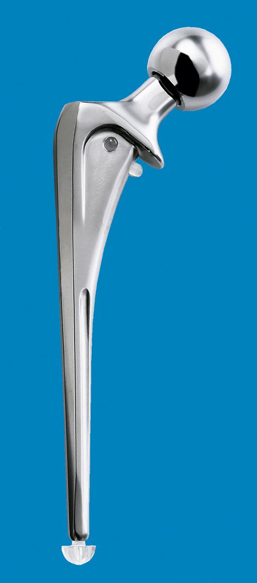
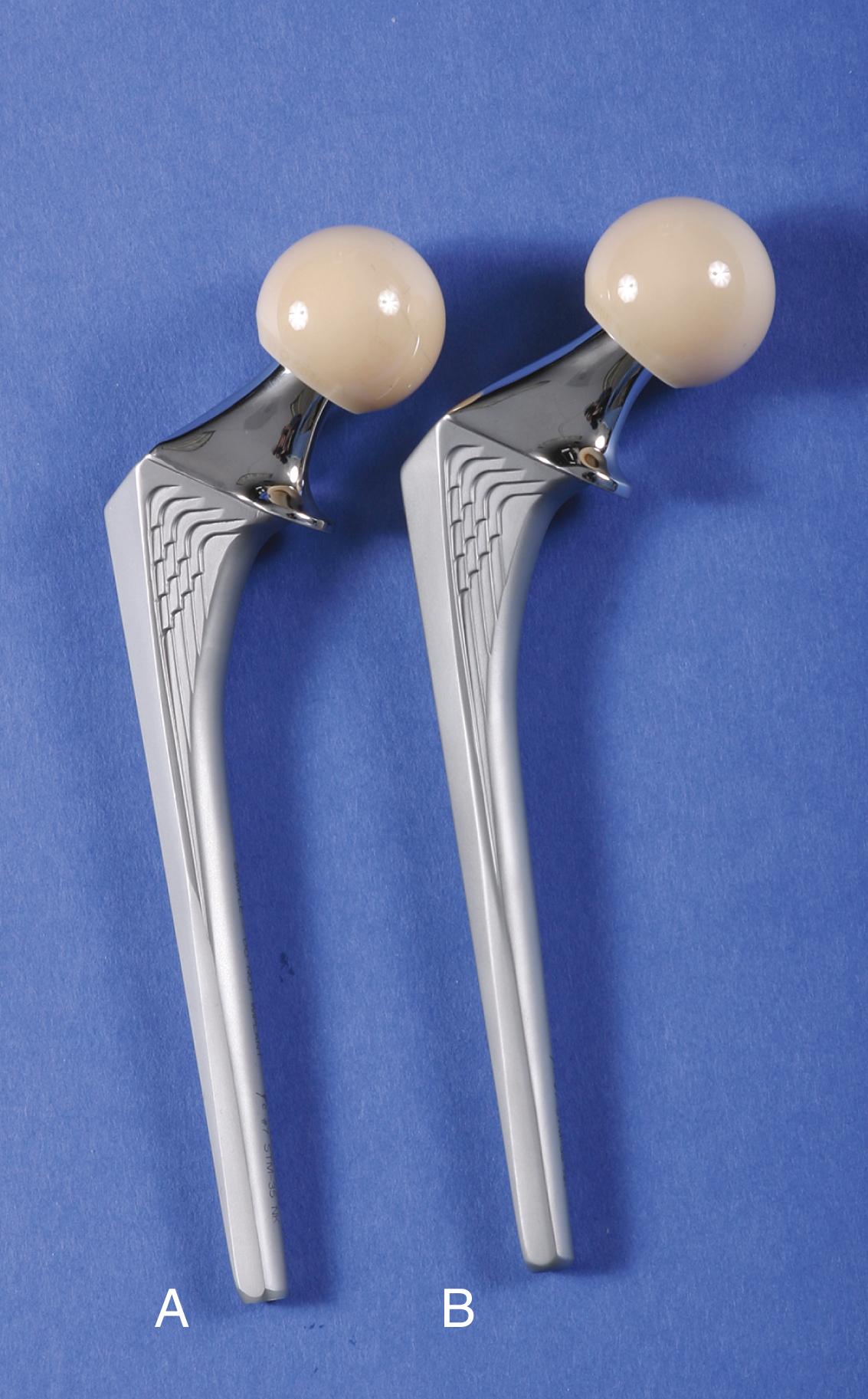
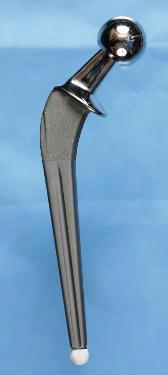
There is concern that even with surface modifications the stem may not remain bonded to the cement. If debonding does occur, a stem with a roughened or textured surface generates more debris with motion than a stem with a smooth, polished surface. Higher rates of loosening and bone resorption were found with the use of an Exeter stem with a matte surface than with an identical stem with a polished surface. Similar findings have been reported when comparing the original polished Charnley stem with its subsequent matte-finish modification. For this reason, interest has been renewed in the use of polished stems for cemented applications. Ling recommended a design that is collarless, polished, and tapered in two planes ( Fig. 3.18 ) to allow a small amount of subsidence and to maintain compressive stresses within the cement mantle. Such implants are often referred to as taper-slip or force-closed devices. A collar on a polished stem is to be avoided since it may prevent this controlled subsidence. Registry data support a lower rate of loosening in the long term with polished stems than with matte finished stems.
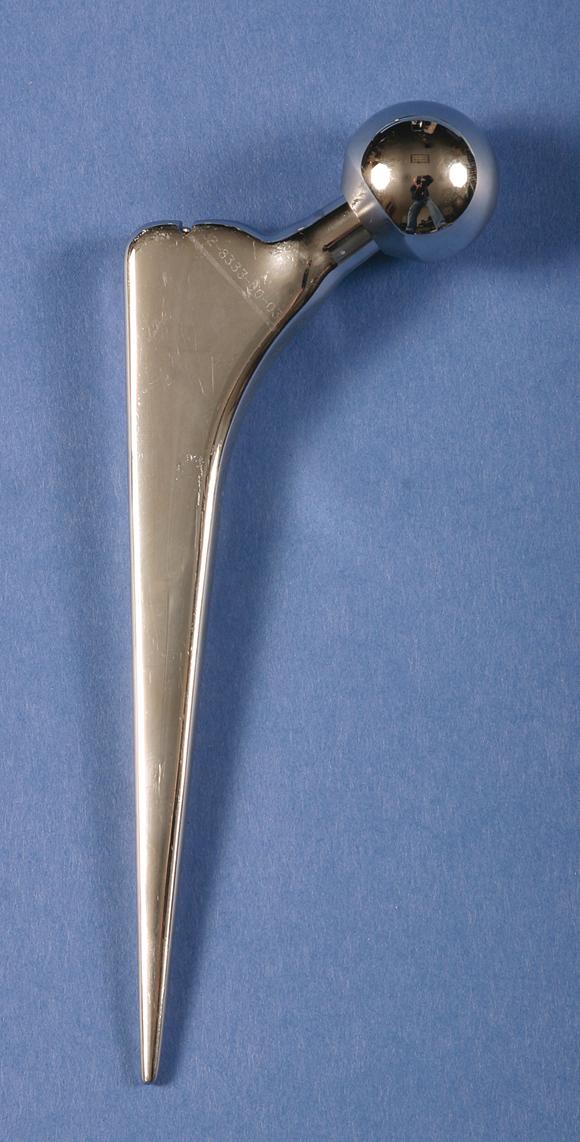
Stems should be available in a variety of sizes (typically four to six) to allow the stem to occupy approximately 80% of the cross section of the medullary canal with an optimal cement mantle of approximately 4 mm proximally and 2 mm distally. Neutral stem placement within the canal lessens the chance of localized areas of thin cement mantle, which may become fragmented and cause loosening of the stem. Some designs have preformed PMMA centralizers that are affixed to the distal or proximal aspects, or both, of the stem before implantation to centralize the stem within the femoral canal and provide a more uniform cement mantle (see Fig. 3.15 ). The centralizers bond to the new cement and are incorporated into the cement mantle.
Finally, the optimal length of the stem depends on the geometry and size of the femoral canal. The stem of the original Charnley component was about 13 cm long. This was long enough to obtain secure fixation in the metaphysis and proximal diaphysis of the femur. A stem of longer length, which engages the isthmus, makes it more difficult to err and place the stem in a varus position. As a result of the normal anterior bow of the femoral canal, however, the tip of the stem may impinge on the anterior cortex or even perforate it when the cortex is thin. In addition, it is technically difficult to occlude the canal below the level of the isthmus adequately, and the result may be an inadequate column of cement around the stem and beyond the tip. The lengths of current stem designs range from 120 to 150 mm. Longer stems are available if the cortex has been perforated, fractured, or weakened by screw holes or other internal fixation devices and particularly for revision procedures.
In the mid-1970s, problems related to the fixation of femoral components with acrylic cement began to emerge. As a result, considerable laboratory and clinical investigations have been performed in an effort to eliminate cement and provide for biologic fixation of femoral components. The two prerequisites for biologic fixation are immediate mechanical stability at the time of surgery and intimate contact between the implant surface and viable host bone. To fulfill these requirements, implants must be designed to fit the endosteal cavity of the femur as closely as possible. Still, the femur must be prepared to some degree to match accurately the stem that is to be inserted. In general, the selection of implant type and size must be more precise than with their cemented counterparts. Current cementless stem designs differ in their materials, surface coating, and shape.
Experience has been confined largely to the use of two materials: (1) titanium alloy with one of a variety of surface enhancements and (2) cobalt-chromium alloy with a sintered beaded surface. Both materials have proved to be satisfactory. Titanium has been recommended by many designers because of its superior biocompatibility, high fatigue strength, and lower modulus of elasticity. Titanium is more notch-sensitive than cobalt-chrome alloy, however, predisposing it to initiation of cracks through metallurgic defects and at sites of attachment of porous coatings. When the stem is of a titanium substrate, the porous surface must be restricted to the bulkier proximal portions of the stem and away from areas that sustain significant tensile stresses, such as on the lateral border of the stem. Titanium alloy has been recommended as the material of choice because its modulus of elasticity is approximately half that of cobalt-chromium alloy and therefore less likely to be associated with thigh pain. However, Lavernia et al. reported titanium alloy and cobalt-chromium alloy stems of an identical tapered design in 241 patients. Thigh pain was unrelated to the material composition of the stem but was more common in patients with a larger stem size.
A variety of surface modifications including porous coatings, grit blasting, plasma spraying, and hydroxyapatite coating have been used to enhance implant fixation. Many cementless femoral component designs feature combinations of these surface enhancements. Although the type and extent of coating necessary is controversial, most experts agree that it should be circumferential at its proximal boundary. Some early porous stem designs used patches or pads of porous coating with intervening smooth areas, which allowed joint fluid to transport particulate debris to the distal aspect of the stem. Schmalzried et al. referred to these extensions of joint fluid as the “effective joint space.” This design feature has been associated with early development of osteolysis around the tip of the stem despite bone ingrowth proximally. Circumferential porous coating of the proximal aspect of the stem provides a more effective barrier to the ingress of particles and limits the early development of osteolysis around the distal aspect of the stem.
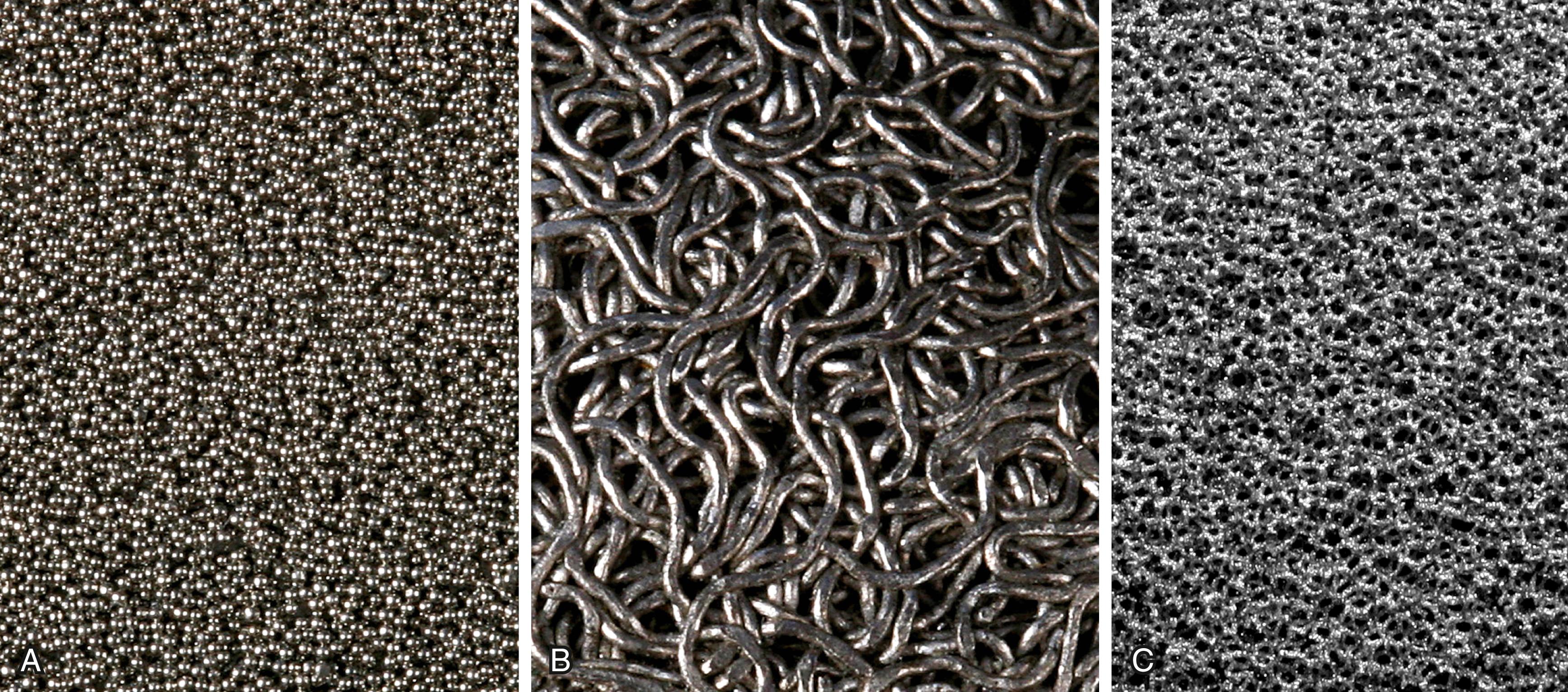
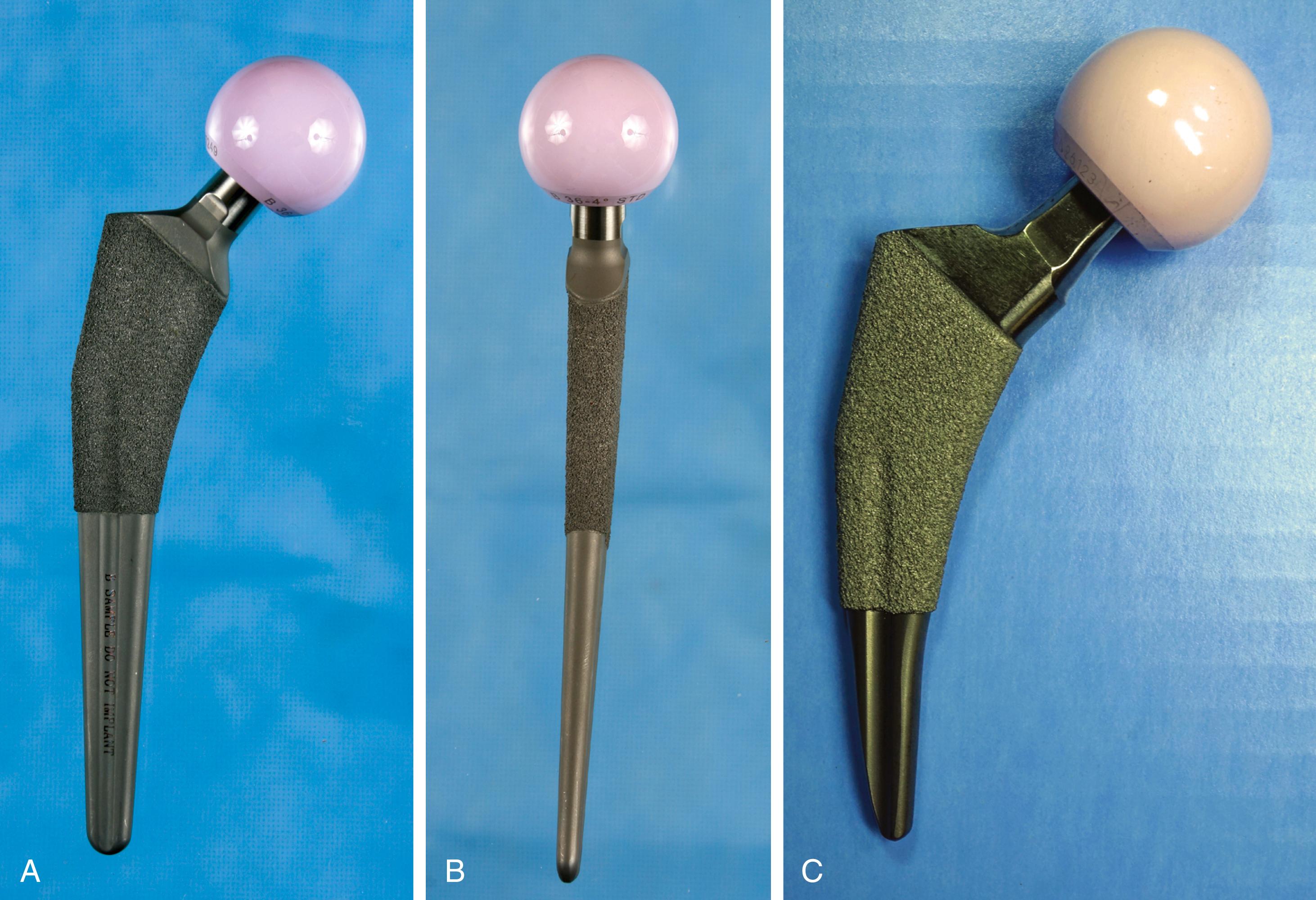
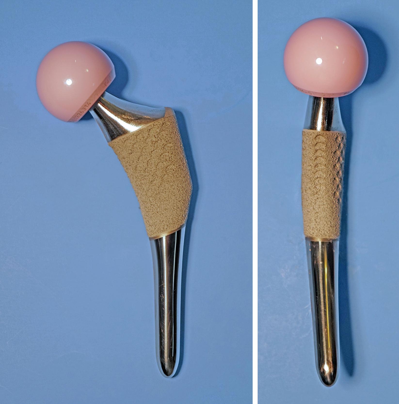
Bone ingrowth into a porous coating has demonstrated durable fixation for a multitude of cementless stem designs. Porous coatings have historically been created by either beads or fiber mesh ( Fig. 3.19A and B ) applied to the stem by sintering or diffusion bonding processes. Both processes require heating of the underlying substrate and can cause significant reduction in the fatigue strength of the implant. A considerable volume of research has determined the optimal pore size for bone ingrowth into a porous surface to be between 100 and 400 μm. Most porous-coated implants currently available have pore sizes in this range. Highly porous metals such as tantalum were initially utilized for cementless fixation of acetabular components but have more recently been applied to femoral stems also ( Fig. 3.19C ). Porous metals have higher porosity than traditional porous coatings, and their high coefficient of friction against cancellous bone may improve their initial stability. Porous tantalum closely resembles the structure of cancellous bone. Rapid and extensive bone ingrowth into this implant surface has been reported.
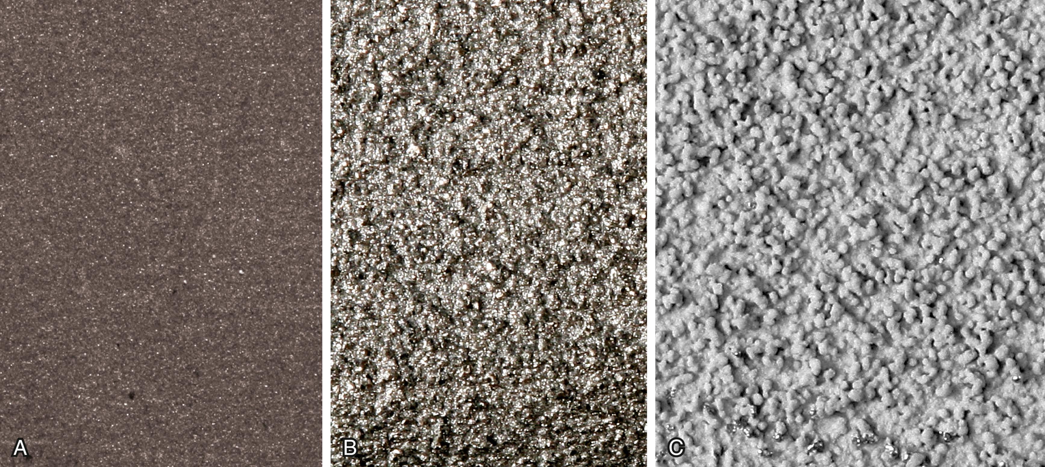
Bone ongrowth implies growth of bone onto a roughened (albeit nonporous) surface. Ongrowth surfaces are created by grit blasting or plasma spray techniques. Grit blasting involves the use of a pressurized spray of aluminum oxide particles to produce an irregular surface ranging from 3 to 8 μm in depth ( Fig. 3.20A ). Plasma spray techniques use high-velocity application of molten metal onto the substrate in a vacuum or argon gas environment and produce a highly textured surface ( Fig. 3.20B ). Heating of the implant is not required, and, consequently, there is little reduction in fatigue strength compared with the application of porous coatings. Hydroxyapatite and other osteoconductive calcium phosphate coatings can also be applied to implants by plasma spray ( Fig. 3.20C ). The thickness of the coating is typically 50 to 155 μm. Although the literature reports mixed results with regard to whether hydroxyapatite coating improves outcomes, there is no evidence that it is deleterious.
The evolution of cementless femoral fixation has resulted in a variety of implants. The shape of a cementless stem determines the areas of the femoral canal where fixation is obtained and the surgical technique required for implantation. Outcomes are also generally more dependent on stem geometry than on either materials or surface enhancements. Khanuja, Vakil, Goddard, and Mont proposed a classification system for cementless stems based on shape. Types 1 through 5 are straight stems, and fixation area increases with type. Type 6 is an anatomic shape.
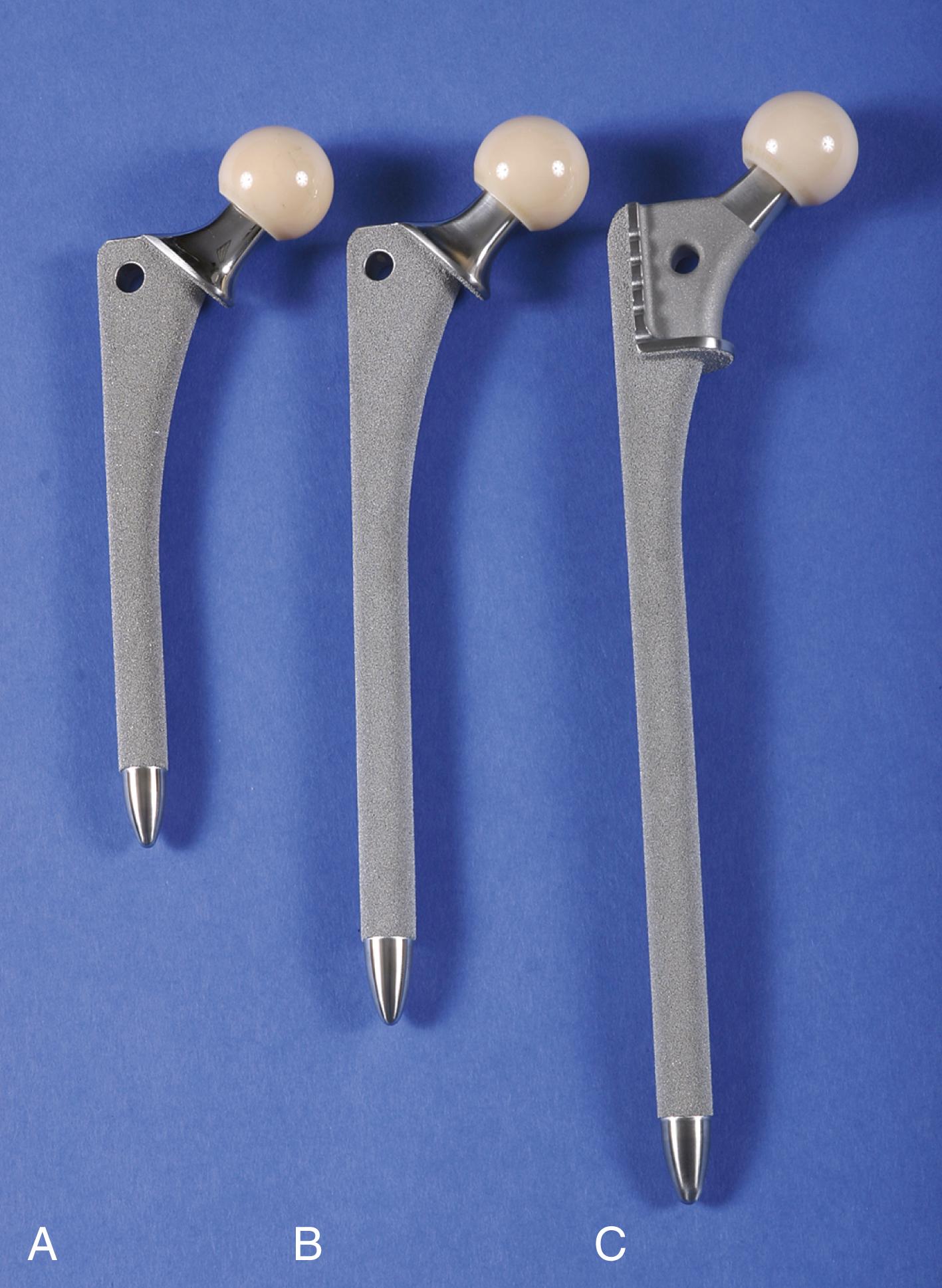
Type 1 stems are so-called single-wedge stems. They are flat in the anteroposterior plane and tapered in the mediolateral plane ( Fig. 3.21 ). Fixation is by cortical engagement only in the mediolateral plane and by three-point fixation along the length of the stem. The femoral canal is prepared by broaching alone, with no distal reaming. Consequently, it is important to ensure that the stem is wedged proximally. In Dorr type A femurs, distal engagement alone risks fracture or rotational instability. Consequently, many of these designs have been modified with reduced distal sizing to avoid this problem. These stems have performed well in Dorr type B and C femurs.
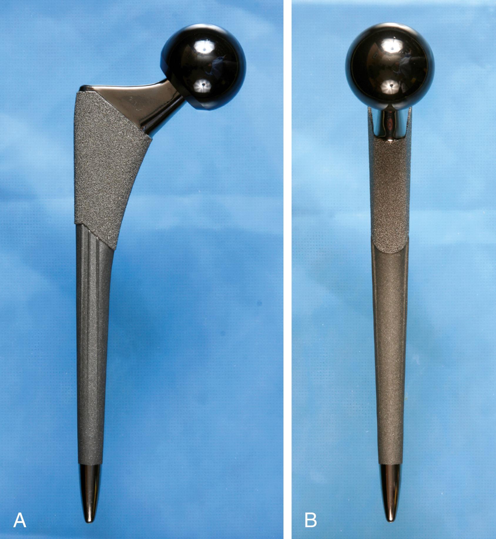
Type 2 stems engage the proximal femoral cortex in both mediolateral and anteroposterior planes. So-called dual-wedge designs fill the proximal femoral metaphysis more completely than type 1 stems ( Fig. 3.22 ). Femoral preparation typically requires distal reaming followed by broaching of the proximal femur. They can be used safely in Dorr type A femurs.
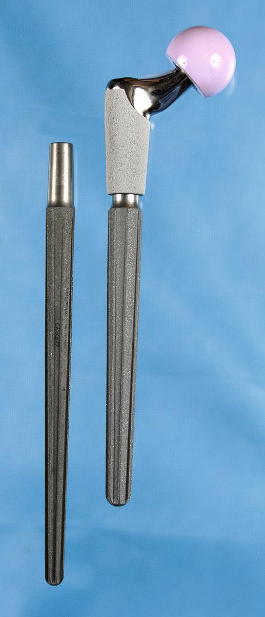
Type 3 represents a more disparate group of implants. These stems are tapered in two planes, but fixation is achieved more at the metaphyseal-diaphyseal junction than proximally as with types 1 and 2. Type 3A stems are tapered with a round conical distal geometry. Longitudinal cutting flutes are added to type 3B stems ( Fig. 3.23 ). These implants have recently gained popularity in complex revision cases. Type 3C implants are rectangular and thus provide four-point rotational support ( Fig. 3.24 ). Such implants have been used extensively in Europe with success.
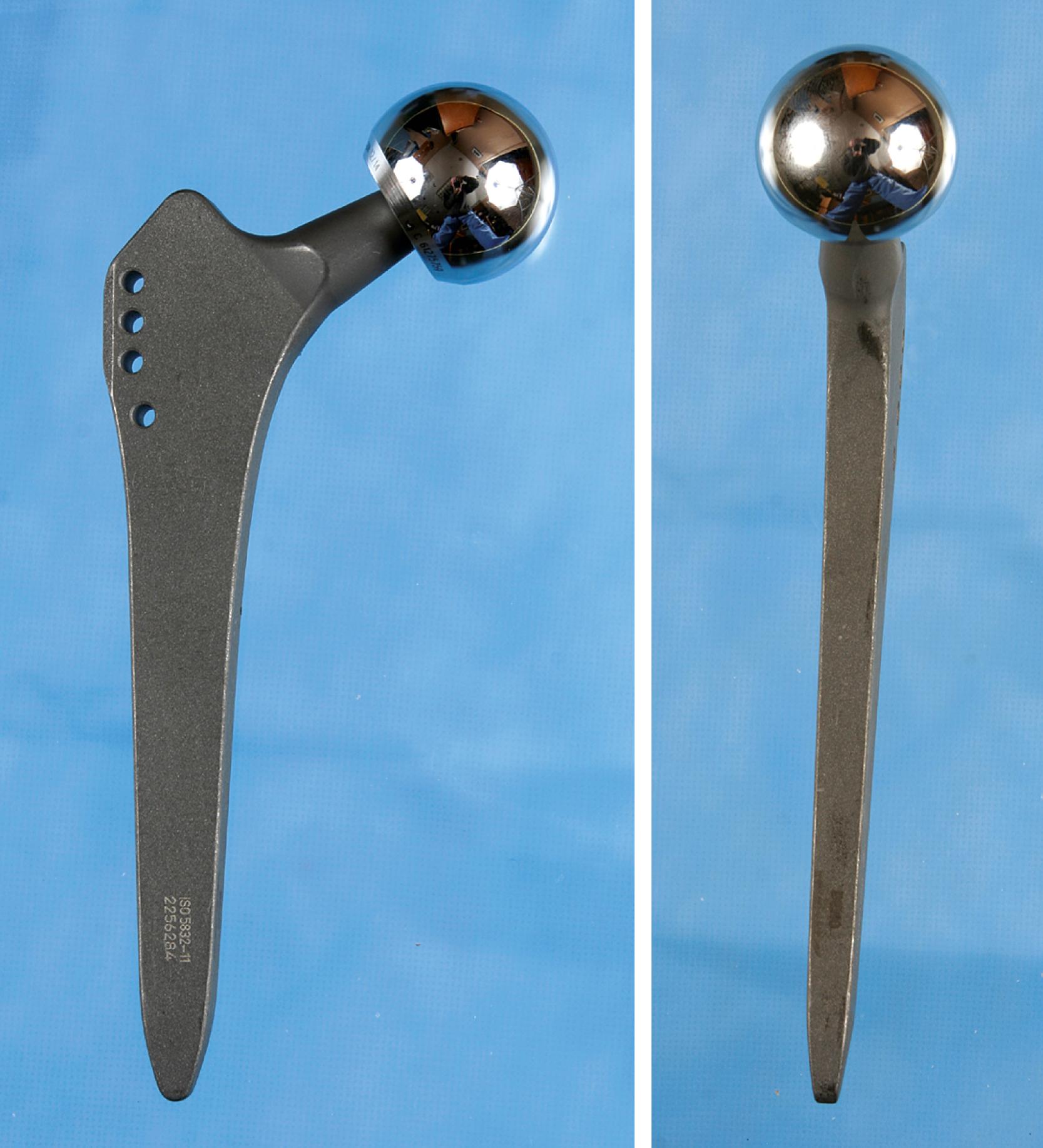
Type 4 are extensively coated implants with fixation along the entire length of the stem. Canal preparation requires distal cylindrical reaming and proximal broaching ( Fig. 3.25 ). Excellent long-term results have been achieved with these implants. Femoral stress shielding and thigh pain have been reported with various designs. Their use in Dorr type C femurs can be problematic because of the large stem diameter required.
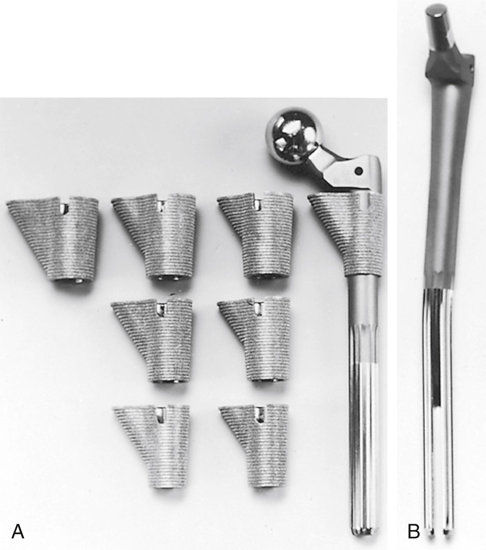
Type 5 or modular stems have separate metaphyseal sleeves and diaphyseal segments that are independently sized and instrumented. Such implants often are recommended for patients with altered femoral anatomy, particularly those with rotational malalignment such as developmental dysplasia. Both stem segments are prepared with reamers, leading to a precise fit with rotational stability obtained both proximally and distally. This feature makes modular stems an attractive option when femoral osteotomy is required ( Fig. 3.26 ). Modular stems can be used for all Dorr bone types, but increased cost and potential problems with modular junctions should be taken into account.
Type 6 or anatomic femoral components incorporate a posterior bow in the metaphyseal portion and variably an anterior bow in the diaphyseal portion, corresponding to the geometry of the femoral canal ( Fig. 3.27 ). Right and left stems are required, and anteversion must be built into the neck segment. Anatomic variability in the curvature of the femur usually requires some degree of overreaming of the canal; if the tip of the stem is eccentrically placed, it impinges on the anterior cortex. This point loading has been suggested to be a source of postoperative thigh pain. The popularity of anatomic stems has declined over the past decade in favor of straight designs.
With cementless devices, the requirements for canal filling often mean the stem must be of sizable diameter. Because stiffness of a stem is proportional to the fourth power of the diameter, an increased prevalence of femoral stress shielding can be seen with larger stems. The mismatch in stiffness between implant and bone also has been cited as a cause of postoperative thigh pain. Current stem designs deal with this problem in several ways. The section modulus of the stem can be changed to allow greater flexibility while leaving the implant diameter unchanged so that stability is not compromised. The addition of deep, longitudinal grooves reduces bending and torsional stiffness. The bending stiffness in the distal third of the stem also can be reduced substantially by splitting the stem in the coronal plane, similar to a clothespin (see Fig. 3.26 ). Tapered distal stem geometries are inherently less stiff than cylindrical ones (see Fig. 3.22 ) and have been associated with minimal thigh pain.
A considerable amount of data supports a superiority of cementless femoral fixation in younger patients. Takenaga et al. reported a series of extensively porous-coated stems in patients 59 years of age or younger. At a minimum of 10 years after surgery no stems showed radiographic signs of loosening or had undergone revision for loosening. Survivorship was better than in a cohort of cemented stems from the same institution. McLaughlin and Lee reported a series of single-wedge design stems in patients younger than 50 years. At a minimum follow-up of 20 years, no stems were revised for aseptic loosening. Costa, Johnson, and Mont reported 96% survivorship at mean follow-up of 5 years in a series of patients who had arthroplasty at a mean age of 20 years. Using a stem fully coated with hydroxyapatite, Jacquot et al. reported a 30-year survival of 93.6% with stem revision as the endpoint. Evidence supporting the use of cementless femoral fixation in patients over the age of 75 is less compelling. Registry data and individual series both call attention to a higher rate of revision for periprosthetic fractures in this population.
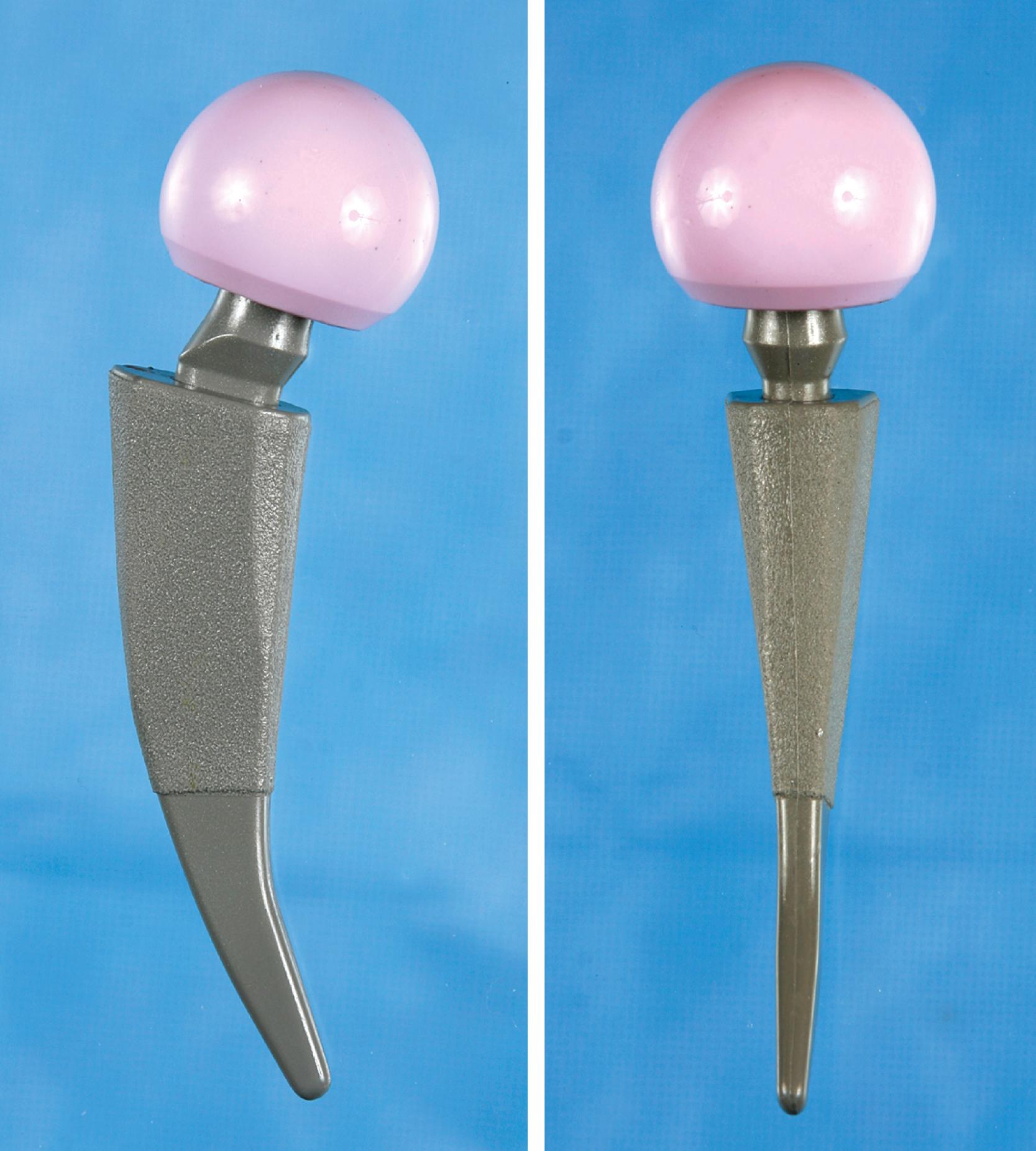
The adoption of minimally invasive surgical techniques has generated interest in shorter bone-sparing femoral implants. Some are novel implants designed to fit within the intact ring of bone of the femoral neck ( Fig. 3.28 ). Others are shortened versions of existing designs described previously (see Fig. 3.21C ). These implants have been used most commonly in minimally invasive anterior approaches where access to the femoral canal is more difficult. A shorter stem also avoids the problem of proximal-distal mismatch encountered with conventional length stems in Dorr type A femurs. Ideally, short femoral stems should allow retention of a longer segment of the femoral neck and increased physiologic load transfer in the proximal femur to reduce bone loss. Data supporting the use of these implants are limited. The surgical technique must be more precise to avoid varus malalignment and undersizing. Subsidence has been reported more commonly with some designs.
Despite the large array of femoral components available, deformity or bone loss from congenital conditions, trauma, tumors, or previous surgery may make it impossible for any standard stem to fit the femur or restore adequately the position of the femoral head. Several types of calcar replacement femoral components (see Fig. 3.25C ) are available for patients with loss of varying amounts of the proximal femur in lieu of the use of bone grafts. Limb salvage procedures for some malignant or aggressive benign bone and soft-tissue tumors may require a customized component. Modular segmental replacement stems also are used in patients with extensive femoral bone loss from multiple failed arthroplasty procedures and periprosthetic fractures ( Fig. 3.29 ). Rarely, a prosthesis may be required to replace the entire femur, incorporating hip and knee arthroplasties.
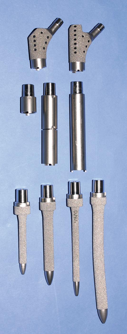
Customized, cementless, CT-generated computer-assisted design/computer-assisted manufacturing (CAD/CAM) prostheses have been recommended when preoperative planning indicates that an off-the-shelf prosthesis cannot provide optimal fit or when excessive bone removal would be required. Such implants require a carefully made preoperative CT scan of the acetabulum, hip joint, and femur. An identical broach is supplied with the implant to prepare the femur. Customized femoral components also have been recommended for revision surgery with proximal femoral osteolysis, congenital hip dislocation, excessively large femurs, and grossly abnormal anatomy and when a fracture has occurred below the tip of a femoral stem. With the proliferation of newer revision stem designs and techniques of femoral osteotomy for revision procedures, custom stems are seldom needed in our practice.
Acetabular components can be broadly categorized as cemented or cementless. Acetabular reconstruction rings also are discussed in this section.
The original sockets for cemented use were thick-walled polyethylene cups. Vertical and horizontal grooves often were added to the external surface to increase stability within the cement mantle, and wire markers were embedded in the plastic to allow better assessment of position on postoperative radiographs. Many of these designs are still in regular use. More recent designs have modifications that ensure a more uniform cement mantle. PMMA spacers, typically 3 mm in height, ensure a uniform cement mantle and avoid the phenomenon of “bottoming out,” which results in a thin or discontinuous cement mantle ( Fig. 3.30 ). A flange at the rim of the component aids in pressurization of the cement as the cup is pressed into position.
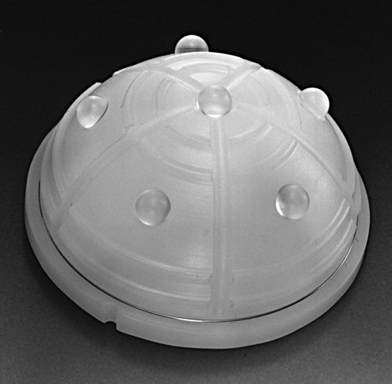
Despite such changes in implant design, the long-term survivorship of cemented acetabular components has not substantially improved. Consequently, there has been a trend toward cementless fixation of acetabular components in most patients. The simplicity and low cost of all-polyethylene components make them a satisfactory option in older, low-demand patients.
At times, cement is also used as the means of fixation of a polyethylene insert into an acetabular component that lacks an intrinsic locking mechanism for the polyethylene or when a dedicated insert is not available for a cementless acetabular component that is to be retained during revision surgery. Cemented acetabular fixation also is used in some tumor reconstructions and when operative circumstances indicate that bone ingrowth into a porous surface is unlikely, as in revision arthroplasty in which extensive acetabular bone grafting has been necessary. In these instances, a cemented acetabular component often is used with an acetabular reconstruction ring (see Fig. 3.36 ).
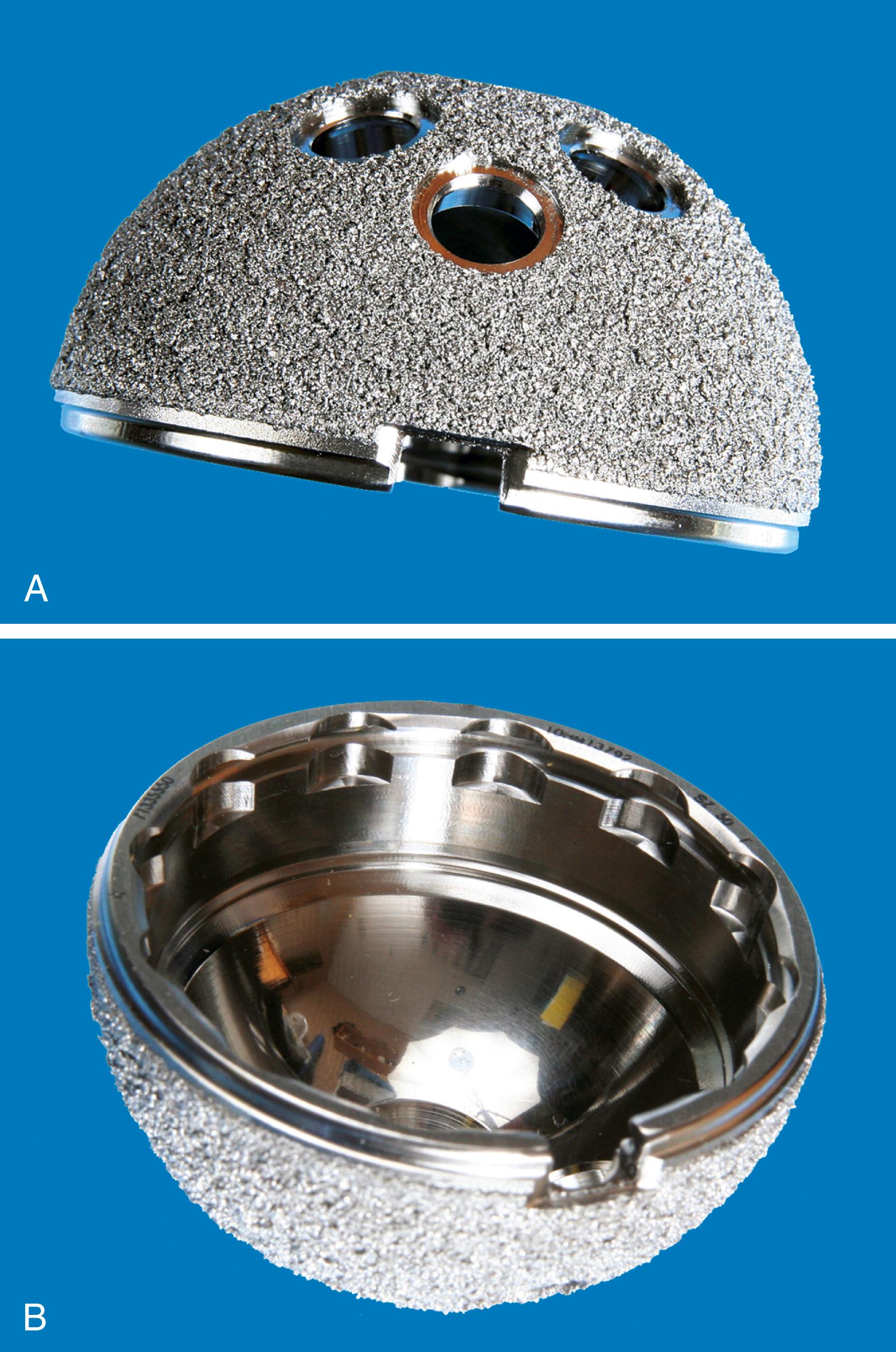
Most cementless acetabular components are porous-coated over their entire circumference for bone ingrowth. Instrumentation typically provides for oversizing of the implant 1 to 2 mm larger than the reamed acetabulum as the primary method of press-fit fixation. Fixation of the porous shell with transacetabular screws has become commonplace but carries some risk to intrapelvic vessels and viscera and requires flexible instruments for screw insertion. Analyses of retrieved porous acetabular components showed that bone ingrowth occurs most reliably in the vicinity of the fixation devices, such as pegs or screws. The most extensive ingrowth has been reported in components initially fixed with one or more screws. Pegs, fins, and spikes driven into prepared recesses in the bone provide some rotational stability, but less than that obtained with screws. The use of these other types of supplemental fixation devices has declined as manufacturers have incorporated highly porous metal coatings with improved initial press-fixation ( Figs. 3.31 and 3.32 ). Solid metal shells without screw holes have not proven beneficial in reducing the presence or size of osteolytic lesions; their use has consequently diminished.
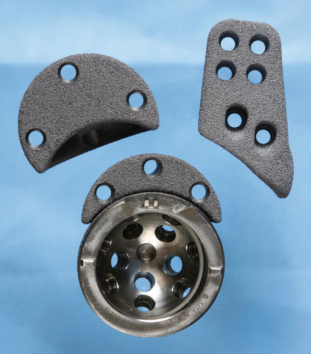
Hydroxyapatite coating has been advocated in the past to enhance bone ingrowth into the porous coating of cementless acetabular components. The process has not demonstrated improved survivorship, and with the introduction of newer porous surfaces, the use of hydroxyapatite coating has declined.
Most systems feature a metal shell with an outside diameter of 40 to 75 mm that is used with a modular insert, also called a liner. With this combination, a variety of femoral head sizes, typically 22 to 40 mm, can be accommodated according to the patient’s need and the surgeon’s preference. The liner must be fastened securely within the metal shell. These mechanisms of fixation have been under increasing scrutiny because in vivo dissociation of polyethylene liners from their metal backings has been reported. In addition, micromotion between the nonarticulating side of the liner and the interior of the shell may be a source of polyethylene debris generation, or “backside wear.” Recognition of this problem has led to improvements in the fixation of the liner within the metal shell, and some designs also have included polishing the interior of the shell. Monoblock acetabular components with nonmodular polyethylene also have been produced to alleviate the problem of backside wear but have not proven to be superior to modular implants.
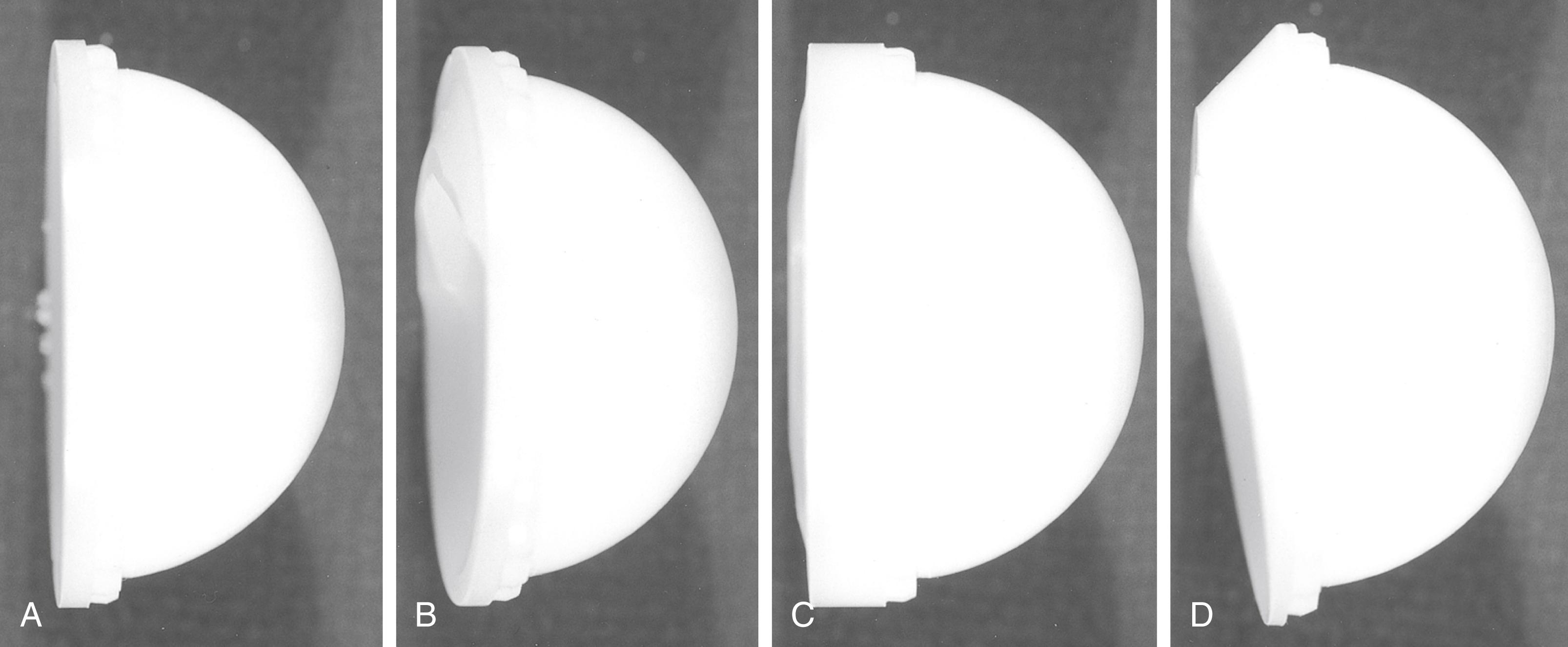
With the adoption of newer bearing surfaces and dual mobility implants (see Fig. 3.35 ), manufacturers have introduced acetabular components that will accept any of a variety of insert types. Newer locking mechanisms typically incorporate a taper junction near the rim for hard bearings. The polyethylene locking mechanism may be recessed within the shell where it is less susceptible to damage if impingement from the femoral neck occurs ( Fig. 3.32B ).
Finally, the issue of excessive wear of thin shells of polyethylene is a major concern. The metal backing must be of sufficient thickness to avoid fatigue failure, and there must be a corresponding decrease in thickness of the polyethylene insert for a component of any given outer diameter. High stresses within the polyethylene are likely when the thickness of the plastic is less than 5 mm, leaving the component at risk for premature failure as a result of wear. To maintain sufficient thickness of the polyethylene, a smaller head size must be used with an acetabular component that has a small outer diameter.
Most modern modular acetabular components are supplied with a variety of polyethylene insert choices. Some designs incorporate an elevation over a portion of the circumference of the rim, whereas others completely reorient the opening face of the socket up to 20 degrees. Still other designs simply lateralize the hip center without reorienting its opening face ( Fig. 3.33 ). Lateralization also allows for the use of a larger-diameter head while maintaining adequate polyethylene thickness. Such designs can compensate for slight aberrations in the placement of the metal shell and improve the stability of the articulation; however, with elevated rim liners, motion can be increased in some directions but decreased in others. An improperly positioned elevation in the liner can cause impingement rather than relieve it, rendering the joint unstable. With larger-diameter femoral heads, elevated rim liners are being used less frequently.
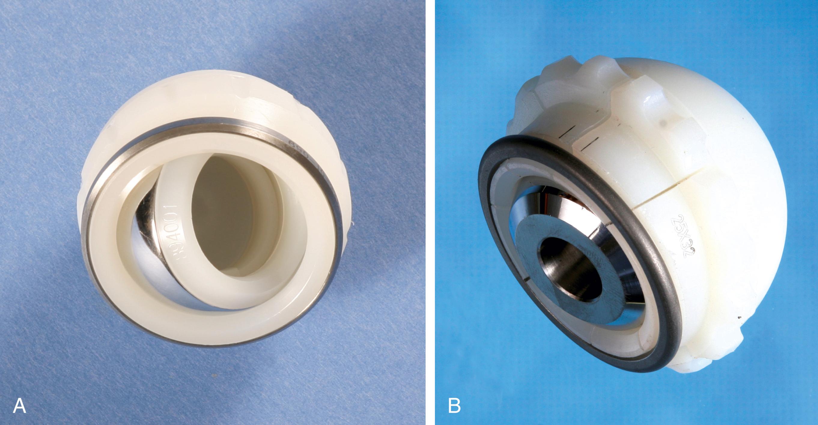
A constrained acetabular component includes a mechanism to lock the prosthetic femoral head into the polyethylene liner. The tripolar-style mechanism features a small inner bipolar bearing that articulates with an outer true liner ( Fig. 3.34A ). The bipolar segment is larger than the introitus of the outer liner, preventing dislocation. Other designs use a liner with added polyethylene at the rim that deforms to capture the femoral head. A locking ring is applied to the rim to prevent escape of the head ( Fig. 3.34B ). Other unique designs are also available from individual manufacturers. Indications for constrained liners include insufficient soft tissues, deficient hip abductors, neuromuscular disease, and hips with recurrent dislocation despite well-positioned implants. Constrained acetabular liners have reduced range of motion compared with conventional inserts. Consequently, they are more prone to failure because of prosthetic impingement. A constrained liner should not be used to compensate for an improperly positioned shell, and skirted femoral heads should be avoided in combination with constrained inserts.
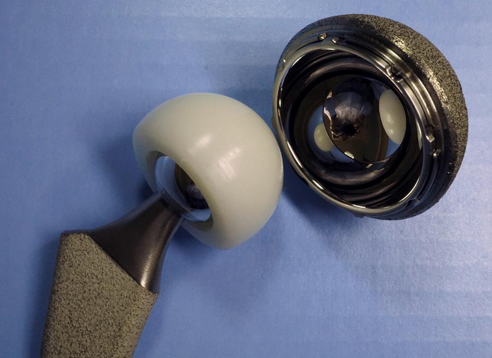
A dual mobility acetabular component is an unconstrained tripolar design. The implant consists of a porous-coated metal shell with a polished interior that accepts a large polyethylene ball into which a smaller metal or ceramic head is inserted ( Fig. 3.35 ) . The two areas of articulation share the same motion center. The design effectively increases the head size and the head-neck ratio of the construct. Implant impingement is reduced and stability is improved without reducing the range of motion as with constrained implants. A modular metal shell and insert are available for cases in which screw fixation may be required. In a large series of primary total hip arthroplasties using a dual mobility implant, Combes et al. reported a dislocation rate of 0.88%. Wegrzyn et al. reported dislocations in 1.5% of revision cases. Also reported are intraprosthetic dislocations between the small head and polyethylene ball. As with constrained acetabular devices, dual mobility components cannot be relied on to compensate for technical errors in implant positioning.
Custom components for acetabular reconstruction rarely are indicated. Most deficient acetabula can be restored to a hemispherical shape, and a standard, albeit large, acetabular component can be inserted. In patients with a large superior segmental bone deficiency, the resulting acetabular recess is elliptical rather than hemispherical. A cementless acetabular component with modular porous metal augments (see Fig. 3.31 ) can be used instead of a large structural graft or excessively high placement of a hemispherical component. Augments of various sizes are screwed into bony defects to support the acetabular component. The augments are joined to the implant with the use of bone cement.
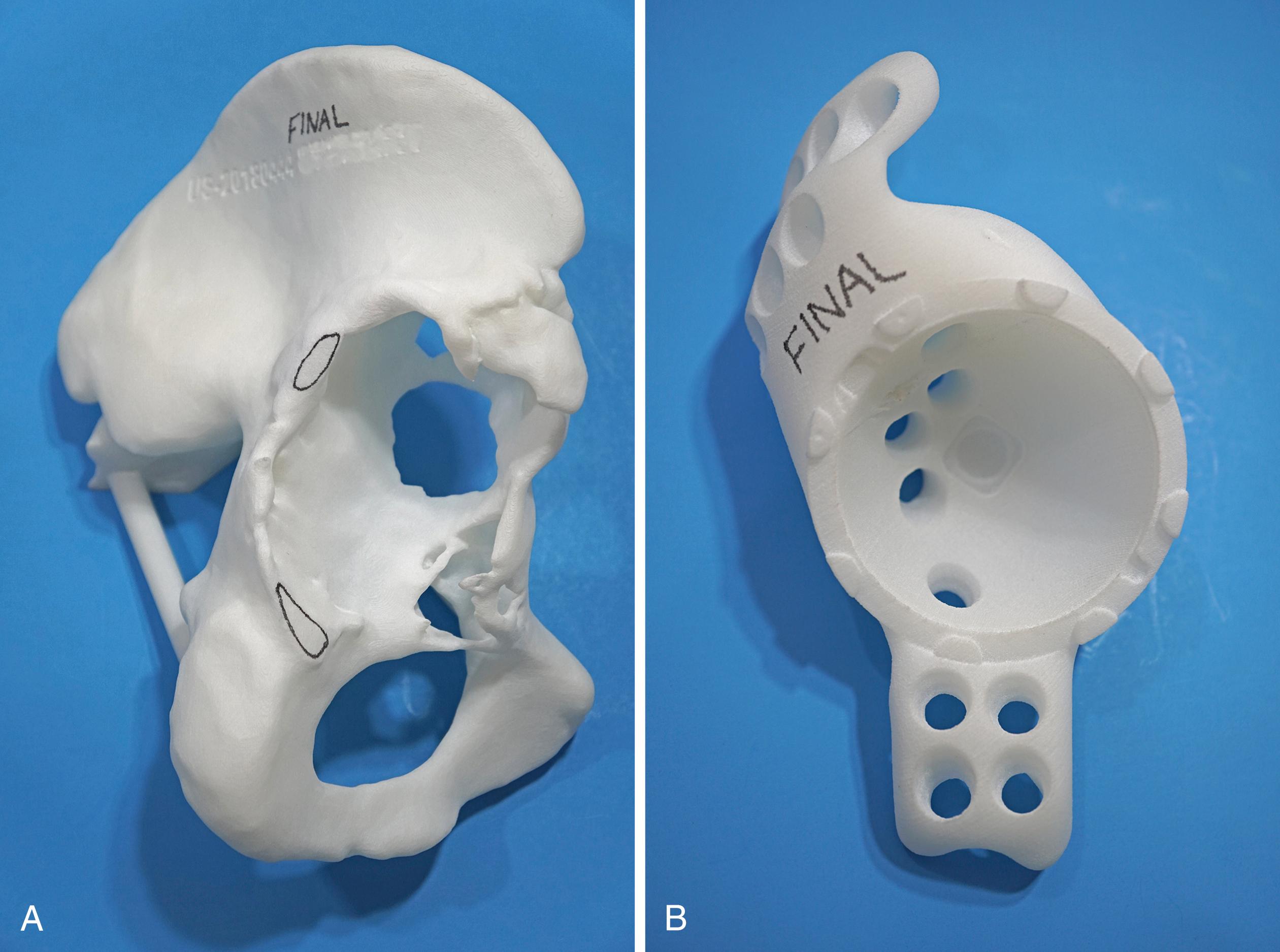
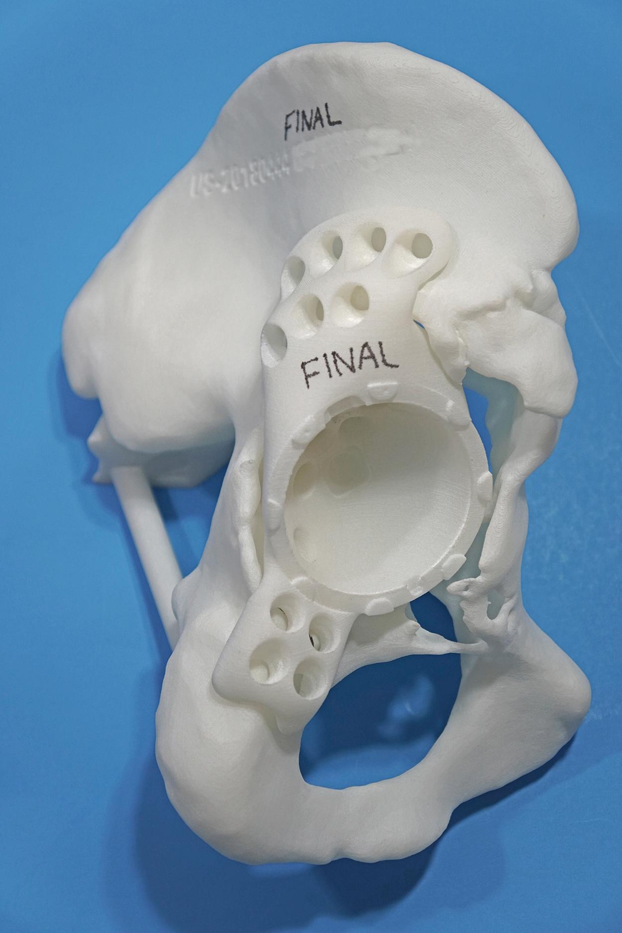
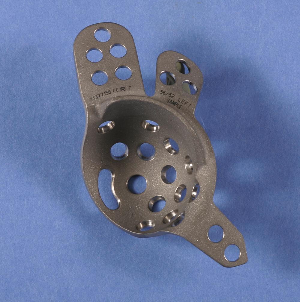
With the introduction of revision implants with augments, custom components for acetabular reconstruction rarely are indicated. When bony deficits are massive, a custom implant can be produced based on a CT scan with subtraction of the metal artifacts. The imaging requirements vary according to the manufacturer. Such implants typically have both superior and inferior flanges that rest on intact bone and provide for additional screw fixation. The placement of the flanges, screw locations, and trajectories can all be built into the plan. Typically, a detailed 3D-printed model of the bony pelvis ( Fig. 3.36 ) and proposed implant are produced before the actual implant is manufactured ( Fig. 3.37 ).
Historically, metal rings, wire mesh, and other materials have been used to improve acetabular fixation. These devices were intended to reinforce cement, and generally their long-term performance was poor. More recently, numerous acetabular reconstruction rings have been introduced to allow bone grafting of the deficient acetabulum behind the ring, rather than relying on cement on both sides of the device. (Cement is used only to secure an all-polyethylene acetabular component to the ring.) The reconstruction ring provides immediate support for the acetabular component and protects bone grafts from excessive early stresses while union occurs. These devices are commonly referred to as antiprotrusio rings and cages.
The preferred devices are those with superior and inferior plate extensions that provide fixation into the ilium and the ischium ( Fig. 3.38 ). Success with these devices depends on selection of the proper device and careful attention to technique. Implantation of the antiprotrusio cage requires full exposure of the external surface of the posterior column for safe positioning and screw insertion. Alternatively, the inferior plate can be inset into a prepared recess in the ischium without the need for inferiorly placed screws. For all types of devices, dome screws are placed before the plates are attached to the external surface of the ilium. Results to date seem to be best when the device is supported superiorly by intact host bone rather than by bone grafts. These implants do not provide for long-term biologic fixation and are prone to fracture and loosening. The advent of highly porous metal implants has reduced the need for cages in current practice. Rarely, an antiprotrusio cage may be used in tandem with a revision acetabular shell. This “cup-cage” construct has greater potential for biologic fixation.
Osteolysis secondary to polyethylene particulate debris has emerged as a notable factor endangering the long-term survivorship of total hip replacements. Several alternative bearings have been advocated to diminish this problem, particularly in younger, more active patients who are at higher risk for rapid polyethylene wear. Newer highly crosslinked polyethylenes have now largely replaced traditional ultra-high molecular weight polyethylene (UHMWPE) in hip arthroplasty. The material is mated with a femoral head of either cobalt-chromium alloy or ceramic. This has become the dominant bearing couple used in hip arthroplasty today. Investigation continues on ceramic-on-ceramic bearings. The initial enthusiasm for large-head metal-on-metal bearings has waned with reports of adverse local tissue response (ALTR) with these implants, and their use has largely been abandoned. Metal-on-metal resurfacing arthroplasty remains a viable option in younger, male patients.
Historically, polyethylene implants have been sterilized by subjecting them to 2.5 Mrad of either electron-beam or gamma radiation. These processes produce free radicals in the material, however, predisposing the polyethylene to oxidation and rendering it more susceptible to wear. Higher doses of radiation can produce polyethylene with a more highly crosslinked molecular structure. Initial testing of this material has shown remarkable wear resistance. Crosslinking is accomplished by either gamma or electron-beam radiation at a dose between 5 and 10 Mrad. However, the radiation process also generates uncombined free radicals. If these are allowed to remain, the material is rendered more susceptible to severe oxidative degradation. The concentration of these free radicals can be reduced by a postirradiation heating process, either remelting or annealing. Remelting entails heating the material above its melting point (approximately 135°C). Free radicals are virtually eliminated with remelting, but the crystallinity of the resulting material is also reduced. The decrease in crystallinity diminishes the material properties of polyethylene, particularly fracture toughness and ultimate tensile strength. Annealing refers to a process of heating the material just below the melting point. This avoids the reduction in crystallinity and consequent reduction in mechanical properties, but annealing is less effective than remelting in extinguishing residual free radicals. Newer manufacturing methods have sought to mitigate the deleterious effects of remelting. Soaking the radiated polyethylene in vitamin E (or vitamin E “doping”) appears to be effective in scavenging free radicals without a remelting stage. Another process applies the radiation in three smaller doses with annealing after each stage. Terminal sterilization is most commonly done with either gas plasma or ethylene oxide because gamma radiation would generate additional free radicals. The processes used by individual manufacturers for production of highly crosslinked polyethylenes are proprietary and differ in the initial resin used, the amount and type of radiation used, the use of postirradiation thermal processing, and the method of terminal sterilization. Although early clinical results for all methods are encouraging, the long-term performance of these materials may vary and will need to be studied individually.
Test data from contemporary hip simulators have shown an 80% to 90% reduction in wear with highly crosslinked polyethylenes. When tested in conditions of third-body wear with abrasive particulates or against a roughened counterface, crosslinked polyethylene has improved wear performance substantially compared with conventional polyethylene. Muratoglu et al. showed that the wear rate of this material is not related to the size of the femoral head, within the range of 22 to 46 mm in diameter. Consequently, larger femoral head sizes can be used. Highly crosslinked polyethylenes remain within current American Society for Testing and Materials standards, but concerns have been raised over the potential for fatigue, delamination, and implant fracture when a thin liner is used to accommodate a large-diameter head. Prior attempts to improve the performance of polyethylene have universally failed. Carbon fiber reinforcement, heat pressing, and Hylamer (DePuy, Warsaw, IN) are notable examples.
Early clinical results have shown reductions in wear that are less dramatic than those predicted in hip simulators. The bedding-in process is similar with highly crosslinked and conventional polyethylenes and affects calculations of wear rates using short-term clinical studies. Longer follow-up is needed to assess the true wear reduction after the bedding-in process is complete and a steady state of wear is reached. It also is important to view reports of wear “reduction” in the context of the quality and performance of the material used as the control.
There are now a sufficient number of studies with 10-year follow-up to conclude that the performance of highly crosslinked polyethylenes surpasses that of conventional polyethylene. Snir et al. found that after an initial bedding-in period, there was an annual mean wear rate of 0.05 mm/year with a first-generation highly crosslinked polyethylene. Using precision radiostereometric analysis, Glyn-Jones et al. measured steady-state wear of only 0.003 mm/year at 10 years. In a series of patients younger than 50 years, Rames et al. observed survivorship of 97.8% at 15 years with no wear-related revisions and a liner wear rate of 0.0185 mm/year. The available data indicate a wear rate for highly crosslinked polyethylenes as well below the generally accepted osteolysis threshold of 0.1 mm/year. Using data from the Australian Orthopaedic Association National Joint Replacement Registry, de Steiger found the 16-year cumulative percentage of revisions for all causes was 6.2% for highly crosslinked polyethylene compared to 11.7% for conventional polyethylene.
Femoral head size appears to have less of an effect on highly crosslinked polyethylene than on conventional material. Allepuz et al. published data aggregated from six national and regional registries that showed no difference in wear rates with 32-mm heads compared with smaller diameter sizes. Lachiewicz, Soileau, and Martell reported no difference in liner wear rates with 36- to 40-mm heads compared with smaller sizes; however, volumetric wear was higher in patients with larger diameter heads. Most of the published data involve head sizes of 32 mm and smaller. Tower et al. reported four fractures of a highly crosslinked polyethylene liner in a design with thin polyethylene at the rim and a relatively vertical position of the acetabular component. Using an excessively thin polyethylene liner purely to accommodate a larger head is still to be avoided.
Highly crosslinked polyethylene liners from most manufacturers are compatible with existing modular acetabular components. The liner can be replaced with the newer material without revising the shell in the event of reoperation for osteolysis, dislocation, or at the time of revision of the femoral component. An array of liner options is available as has been the case with conventional polyethylene (see Fig. 3.33 ).
Alumina ceramic has many properties that make it desirable as a bearing surface in hip arthroplasty. Because of its high density, implants have a surface finish smoother than metal implants. Ceramic is harder than metal and more resistant to scratching from third-body wear particles. The liner wear rate of alumina-on-alumina has been shown to be 4000 times less than cobalt-chrome alloy-on-polyethylene. Hamadouche et al. measured ceramic wear at less than 0.025 mm/year in a series of patients with a minimum of 18.5 years’ follow-up.
Early ceramic implants yielded disappointing clinical results because of flawed implant designs, inadequate fixation, implant fracture, and occasional cases of rapid wear with osteolysis. Numerous improvements have been made in the manufacture of alumina ceramics since the 1980s. Hot isostatic pressing and a threefold decrease in grain size have substantially improved the burst strength of the material. Refinements in the tolerances of the Morse taper have reduced the incidence of ceramic head fracture further. In addition, proof testing validates the strength of each individual implant before release. Ceramic head fracture is more common with smaller head sizes and shorter neck lengths. A 28 mm head with short neck length will have less material between the corner of the taper bore and articulating surface than a 36 mm head with longer neck length. Application of a ceramic femoral head onto a stem trunnion with wear or surface damage found at revision surgery can produce uneven load distribution within the head and contribute to fracture. Consequently, manufacturers have produced ceramic heads fitted with a metal sleeve for use in these circumstances.
Impingement between the femoral neck and rim of the ceramic acetabular component creates problems unique to this type of articulation. Impact loading of the rim can produce chipping or complete fracture of the acetabular insert. Repetitive contact at extremes of motion also can lead to notching of the metal femoral neck by the harder ceramic and initiate failure through this relatively thin portion of the implant. In past series, ceramic wear has been greater when the acetabular component has been implanted in an excessively vertical orientation. Ceramic-on-ceramic arthroplasties may be more sensitive to implant malposition than other bearings. “Stripe wear” has been reported on retrieved ceramic heads. This term describes a long, narrow area of damage resulting from contact between the head and the edge of the ceramic liner. Microseparation of the implants during the swing phase of gait is a recognized phenomenon. Walter et al. mapped the position of stripes on retrieved implants, however, and proposed they occur with edge loading when the hip is flexed, as with rising from a chair or stair climbing.
Enthusiasm for ceramic-on-ceramic implants has been somewhat tempered by reports of reproducible noise, particularly squeaking. The incidence is generally low but in some series has exceeded 10% and has been a source of dissatisfaction requiring revision. The onset of squeaking usually occurs more than 1 year after implantation, and the development of stripe wear has been implicated in noise generation. A specific cementless femoral component with unique metallurgy and taper size has been implicated in several reports. Vibrations generated at the articulating surfaces may be amplified by a more flexible stem, resulting in audible events. The etiology of squeaking has not been fully elucidated and is likely multifactorial.
Osteolysis has been reported around first-generation alumina ceramic implants in instances of high wear. Wear particles are typically produced in smaller numbers and are of smaller size than seen with polyethylene, however, and the cellular response to ceramic particles seems to be less. Alumina ceramic is inert, and ion formation does not occur. There have been no adverse systemic effects reported with ceramic bearings.
Ongoing investigation with composites of alumina and zirconia ceramic (BIOLOX delta, CeramTec GmbH, Plochingen, Germany) holds promise for further improvement in the material properties of these implants. Excellent wear properties and increased fracture toughness have been reported for this material. In a series of delta ceramic-on-ceramic total hips in patients younger than 50 years, Kim et al. found excellent survivorship, but 10% still experienced noise generation including squeaking. Blakeney et al. reported a 23% incidence of squeaking when a large-diameter (32 to 48 mm head) delta ceramic-on-ceramic couple was used. The incidence of head fracture with delta ceramic is approximately 1 in 100,000 (0.001%) compared to 1 in 5000 (0.0201%) with pure alumina ceramic.
Acetabular components include a ceramic insert that mates with a metal shell by means of a taper junction. Lipped and offset liners are unavailable. The locking mechanism for a given implant may not be compatible with other types of inserts. Chipping of the insert on implantation has been reported in multiple series. Special care should be taken during the operative assembly of the acetabular component to ensure that the insert is properly oriented before impaction. Metal backing of the insert has been advocated by one manufacturer to prevent insertional chips and protect the rim of the ceramic from impingement. Alumina ceramic femoral heads are manufactured with only a limited range of neck lengths, and skirted heads are unavailable. Careful preoperative planning with templates is required to ensure that the neck resection is made at an appropriate level for restoration of hip mechanics with the range of neck lengths available.
Oxidized zirconium (OXINIUM, Smith & Nephew, Memphis, TN) is a zirconium metal alloy that is placed through an oxidation process to yield an implant with a zirconia ceramic surface of approximately 5 μm in thickness. The enhanced surface is integral to the metal substrate and not a surface coating. So-called ceramicized metals have the same surface hardness, smoothness, and wettability of typical ceramics, but are not susceptible to chipping, flaking, or fracture. Compared with cobalt chromium alloy, the material contains no detectable nickel and has therefore been recommended for patients with demonstrated metal hypersensitivity. Oxidized zirconium is currently available only in femoral head components mated with polyethylene and not as a ceramic-on-ceramic couple. Reduced wear has been reported when oxidized zirconium is mated with a conventional polyethylene acetabular component. Aoude et al. found no difference in wear rates between cobalt chromium and oxidized zirconium when mated with highly crosslinked polyethylene. The material is more prone to surface damage than conventional ceramic heads after episodes of dislocation.
So-called trunnionosis describes the process of fretting corrosion that may occur between a femoral component trunnion and a cobalt-chrome alloy femoral head leading to adverse local tissue response. The factors contributing to this phenomenon have not been fully elucidated but appear to be more common than previously recognized. The emergence of this problem combined with the reduced fracture risk with newer ceramics has led to an increase in the use of ceramic and ceramicized metal heads worldwide. Some large database studies have also reported a lower risk of infection with ceramic bearings. The reason for this association is unclear.
Originally, the primary indication for THA was the alleviation of incapacitating arthritic pain in patients older than age 65 years whose pain could not be relieved sufficiently by nonsurgical means and for whom the only surgical alternative was resection of the hip joint (Girdlestone resection arthroplasty) or arthrodesis. Of secondary importance was the improved function of the hip. After the operation had been documented to be remarkably successful, the indications were expanded to include the other disorders listed in Box 3.1 .
Inflammatory arthritis
Rheumatoid
Juvenile idiopathic
Ankylosing spondylitis
Osteoarthritis (degenerative joint disease, hypotrophic arthritis)
Primary
Secondary
Developmental dysplasia of hip
Coxa plana (Legg-Calvé-Perthes disease)
Posttraumatic
Slipped capital femoral epiphysis
Paget disease
Hemophilia
Osteonecrosis
Idiopathic
Post fracture or dislocation
Steroid induced
Alcoholism
Hemoglobinopathies (sickle cell disease)
Lupus
Renal disease
Caisson disease
Gaucher disease
Slipped capital femoral epiphysis
Failed reconstruction
Osteotomy
Hemiarthroplasty
Resection arthroplasty (Girdlestone procedure)
Resurfacing arthroplasty
Acute fracture, femoral neck and trochanteric
Nonunion, femoral neck and trochanteric fractures
Pyogenic arthritis or osteomyelitis
Hematogenous
Postoperative
Tuberculosis
Hip fusion and pseudarthrosis
Bone tumor involving proximal femur or acetabulum
Hereditary disorders (e.g., achondroplasia)
Historically, patients 60 to 75 years old were considered the most suitable candidates for THA, but since the 1990s this age range has expanded. With an aging population, many older individuals are becoming candidates for surgery. In a meta-analysis reviewing the impact of advanced age on outcomes of lower extremity arthroplasty, Murphy et al. found that the most elderly patients were at higher risk for mortality, complications, and longer length of stay. Nonetheless, these patients experienced significant gains in pain relief, and activities of daily living and were satisfied with the outcome of arthroplasty surgery.
The 1994 National Institutes of Health Consensus Statement on Total Hip Replacement concluded that “THR [total hip replacement] is an option for nearly all patients with diseases of the hip that cause chronic discomfort and significant functional impairment.” In younger individuals, THA is not the only reconstruction procedure available for a painful hip; the expanding field of hip preservation (see Chapter 6 ) provides surgeons with a variety of options that may delay or obviate the need for arthroplasty.
Femoral or periacetabular osteotomy should be considered for young patients with osteoarthritis if the joint is not grossly incongruous and satisfactory motion is present. Periacetabular osteotomy in patients with dysplasia may decrease the need for structural bone grafting if later conversion to arthroplasty is needed. If an osteotomy relieves symptoms for 10 years or more, and then an arthroplasty is required, the patient will have been able to engage in more physical activity, bone stock will have been preserved, and the patient will be older and less physically active and will need the use of an arthroplasty for fewer years. Core decompression and osteotomy should be considered for patients with idiopathic osteonecrosis of the femoral head, especially when involvement is limited. Management of femoroacetabular impingement should be considered in suitable candidates. Arthrodesis is performed less frequently today, but is still a viable option for young, vigorous patients with unilateral hip disease and especially for young, active men with osteonecrosis or posttraumatic arthritis. If necessary at a later age, the arthrodesis can be converted to a THA. Finally, some designs of hip resurfacing (see Chapter 4 ) have been successful and remain an alternative to THA in young, active men.
Before any major reconstruction of the hip is recommended, conservative measures should be advised, including weight loss, nonopioid analgesics, reasonable activity modification, low-impact exercise, and ambulatory aids. These measures may relieve the symptoms enough to make an operation unnecessary or at least delay the need for surgery for a significant period.
Surgery is justified if, despite these measures, pain at rest and pain with motion and weight bearing are severe enough to prevent the patient from working or from carrying out activities of daily living. Pain in the presence of a degenerative or destructive process in the hip joint as evidenced on imaging studies is the primary indication for surgery. In our opinion, patients with limitation of motion, limp, or leg-length inequality but with little or no hip pain are not candidates for THA.
In a study of a large inpatient database, Rasouli et al. found a higher risk of systemic complications with bilateral total hip procedures carried out under a single anesthetic. Stavrakis et al. found a higher rate of sepsis, but no difference in other complications. The major indication is a medically fit patient with bilateral severe involvement with stiffness or fixed flexion deformity because rehabilitation may be difficult if surgery is done on one side only. Elderly patients with other comorbidities are not suitable candidates for such a procedure. A documented patent ductus arteriosus or septal defect is an absolute contraindication. More intensive intraoperative monitoring, including an arterial line, pulmonary artery catheter, and urinary catheter, is recommended. The surgeon should decide in concert with the anesthesiologist as to whether the second procedure could be completed safely.
Absolute contraindications for THA include active infection of the hip joint or any other region and any unstable medical illnesses that would significantly increase the risk of morbidity or mortality. Asymptomatic bacteriuria has not been associated with postoperative surgical site infections and should not be considered a contraindication.
Hip arthroplasty for degenerative and traumatic conditions is a major cost center for payors. Over the past decade, a greater burden has been placed on both surgeons and institutions to reduce perioperative complications, minimize readmissions, and maintain favorable outcomes, all while reducing the cost of the episode of care.
A thorough general medical evaluation, including laboratory tests, is a recognized prerequisite that affords the clinician the opportunity to uncover and treat various problems before surgery. Comorbidities known to be inherent to elderly patients should be considered, especially cardiopulmonary disease, renal insufficiency, malnutrition, and the propensity for thromboembolism. Functional limitations from an arthritic hip may mask the symptoms of coronary or peripheral vascular disease. Various models of risk stratification have identified a number of potentially modifiable factors that may be addressed preoperatively in order to minimize the risk of complications.
Cardiovascular complications are one of the most common causes of perioperative mortality and hospital readmission. Patients with a known history of cardiac disease or the presence of new symptoms should prompt a cardiology consultation. Aspirin, clopidogrel, and other antiplatelet medications are best discontinued 7 to 10 days before surgery. The presence of vascular stents presents a particular dilemma that should be managed in cooperation with a cardiac consultant. If clopidogrel is to be discontinued before surgery, then it is acceptable to continue aspirin and restart clopidogrel as soon as the bleeding risk at the surgery site permits. Oral anticoagulants such as warfarin and factor Xa inhibitors should be discontinued in sufficient time for coagulation studies to return to normal. A bridging program with a short-acting anticoagulant such as enoxaparin may be required when discontinuing warfarin.
The prevalence of obesity has increased dramatically in Western societies and has been repeatedly identified as a risk factor for delayed wound healing, deep infection, cardiac events, and kidney injury. The risk of infection increases gradually with elevation of body mass index (BMI). There is no definitive BMI at which surgery is contraindicated, but studies frequently stratify risk according to a BMI greater or less than 40 kg/m 2 (class III, morbid obesity). A delay in surgery with a structured weight reduction diet plan should be encouraged for these patients. The role of bariatric surgery before arthroplasty and its effect on outcomes remains undetermined.
Diabetes mellitus has consistently been recognized as a risk factor for postoperative complications, particularly infection. Preoperative screening for HbA1c elevation identifies patients with poor glycemic control over a period of 2 to 3 months. The literature is inconclusive regarding a threshold value of HbA1c that is predictive of subsequent infection. Cancienne et al. identified a HbA1c of more than 7.5% as a significant risk factor for postoperative joint infection. The Second International Consensus Meeting on Musculoskeletal Infection recommended that the upper threshold for HbA1c that may be predictive of subsequent joint infection is most likely to be within the range of 7.5% to 8%. Screenings finding a higher value should be referred for glycemic control prior to surgery.
Current tobacco use has been shown to increase the risk of wound complications in many types of surgery, including arthroplasty. Duchman et al. reported current smokers had a 1.8% incidence of wound complications compared to 1.1% in nonsmokers. Smoking cessation for at least 6 weeks before surgery is recommended to mitigate this risk. Compliance can be assessed by measuring the blood level of cotinine, a metabolite of nicotine.
Patients having nasal colonization with Staphylococcus aureus are at increased risk for infection following hip arthroplasty. Some institutions have instituted screening for nasal MSSA/MRSA colonization with polymerase chain reaction assays. Nasal administration of mupirocin, povidone-iodine, and chlorhexidine products have all been used for decolonization. Universal treatment without individual screening is the most cost-effective modality.
Preoperative anemia, defined by the World Health Organization (WHO) as a Hb level in men less than 13.0 g/dL and 12.0 g/dL for women has been identified as an independent predictor for complications including infection. Perioperative blood transfusion has also been associated with complications including mortality, sepsis, and thromboembolism. Preoperative iron supplementation and erythropoietin administration can decrease the need for allogeneic transfusion. The perioperative use of tranexamic acid and a comprehensive institutional blood management protocol are also important adjuncts for reducing transfusions.
A low BMI (less than 18.5 kg/m 2 ) is associated with a higher risk for infection and may be a surrogate for poor nutritional status in the elderly. Low serum albumin, prealbumin, transferrin, and total lymphocyte count are indicative of poor nutrition and/or anemia.
Many herbal medications and nutritional supplements may cause increased perioperative blood loss, and we recommend that these medications be discontinued preoperatively. Pyogenic skin lesions should be eradicated, and preoperative skin preparation with chlorhexidine for several days should be considered. Dental problems, as well as urinary retention caused by prostatic or bladder disease, should be addressed before surgery.
If a patient has a history of previous surgery, purulent drainage from the hip, or other indications of ongoing infection, laboratory investigation including erythrocyte sedimentation rate (ESR) and C-reactive protein (CRP), nuclear scans, and a culture and sensitivity determination of an aspirate of the hip are advisable before surgery. Infection must be suspected if part of the subchondral bone of the acetabulum or femoral head is eroded or if bone has been resorbed around an internal fixation device.
The physical examination should include the spine and the upper and lower extremities. The soft tissues around the hip should be inspected for any inflammation or scarring where the incision is to be made. Gentle palpation of the hip and thigh may reveal areas of point tenderness or a soft-tissue mass. The strength of the abductor musculature should be determined by the Trendelenburg test. The lengths of the lower extremities should be compared, and any fixed deformity should be noted. Adduction contracture of the hip can produce apparent shortening of the limb despite equally measured leg lengths. Abduction contracture conversely produces apparent lengthening. Fixed flexion deformity of the hip forces the lumbar spine into lordosis on assuming an upright posture and may aggravate lower back pain symptoms. Conversely, fixed lumbar spine deformity from scoliosis or ankylosing spondylitis may produce pelvic obliquity, which must be taken into account when positioning the implants. When the hip and the knee are both severely arthritic, usually the hip should be operated on first. Hip arthroplasty may alter knee alignment and mechanics. Also, knee arthroplasty is technically more difficult when the hip is stiff, and rehabilitation would be hampered.
An alternative or additional diagnosis should be considered. The complaint of “hip pain” can be brought about by a variety of afflictions, and arthritis of the hip joint is one of the less common ones. True hip joint pain usually is perceived in the groin and lateral hip, sometimes in the anterior thigh, and occasionally in the knee. Arthritic pain usually is worse with activity and improves to some degree with rest and limited weight bearing. Pain in atypical locations and of atypical character should prompt a search for other problems. Pain isolated to the buttock or posterior pelvis often is referred from the lumbar spine, sacrum, or sacroiliac joint. Arthritis often coexists in the hip and lumbar spine. A THA done to relieve symptoms predominantly referred from the lumbar spine would do little to improve the patient’s condition. Likewise, surgical intervention in the face of mild hip arthritis when the pain is actually caused by unrecognized vascular claudication, trochanteric bursitis, pubic ramus fracture, or an intraabdominal problem subjects the patient to needless risk.
The Harris, Iowa (Larson), Judet, Andersson, and d’Aubigné and Postel systems for recording the status of the hip before surgery are useful for evaluating postoperative results. Pain, ability to walk, function, mobility, and radiographic changes are recorded. As yet, no particular hip rating system has been uniformly adopted. The Harris system is the most frequently used ( Box 3.2 ).
Adoption of a single rating system by the orthopaedic community would help standardize the reporting of results. Rating systems have been criticized as being subjective, for downgrading the importance of pain relief, and for emphasizing range of motion rather than functional capabilities as a result of hip motion. Improved motion in the hip is of little benefit if one is still unable to dress the foot and trim the toenails. The Western Ontario and McMaster Universities Osteoarthritis Index (WOMAC) considers the functional abilities of patients with hip arthritis in greater depth than specific hip rating systems. The 36-item short-form health survey (SF-36) is a more generic survey of health and well-being. These two tools often are used in addition to a hip rating score in reporting results. Finally, patient reported outcome measures (PROMs) have become increasingly important in evaluating outcomes by hospital administrators, insurance carriers, and policymakers. The Hip Disability and Osteoarthritis Outcome Score (HOOS), Jr is a six-question survey of pain, function, and daily living derived from the HOOS. The survey is efficient to administer and has been validated and endorsed by major orthopaedic societies. The Veterans RAND 12-Item Health Survey (VR-12) and the Patient-Reported Outcomes Measurement Information System (PROMIS Global-10) are both short-form instruments to measure general physical and mental health apart from the hip.
General inhalation anesthesia or regional anesthesia can be used for the surgery. The choice should be made in collaboration with the anesthesiologist and may be based on institutional protocols or the specific needs of the patient. The introduction of multimodal pain management protocols has been an important adjunct to the surgical anesthetic. Preemptive analgesia including lumbar plexus blockade, periarticular injection of long-acting local anesthetics, celecoxib, gabapentin, intravenous or oral acetaminophen, and long-acting oral analgesics such as tramadol have helped reduce the need for more potent opioids.
Finally, preoperative education classes and institutional rehabilitation protocols have proven to be useful adjuncts in shortening hospital stays and reducing readmissions. With careful patient selection, proactive management of comorbidities, preoperative education, and the use of preemptive analgesia, we have reduced length of stay for most patients to a single hospital day. In carefully selected younger patients, we are now performing THA as an outpatient procedure in both hospital and surgery center settings. As payers, including CMS (Centers for Medicare & Medicaid Services) and private insurers, transition to bundled payment methodologies, strategies to reduce cost while maintaining patient safety will become even more important for maintaining surgeon compensation for hip arthroplasty procedures.
Before surgery, radiographs of the hips are reviewed and, if indicated, radiographs of the spine and knees are obtained. An anteroposterior view of the pelvis showing the proximal femur and a lateral view of the hip and proximal femur are the minimal views required. Radiographs of the pelvis should be reviewed specifically to evaluate the structural integrity of the acetabulum, to estimate the size of the implant required and how much reaming would be necessary, and to determine whether bone grafting would be required. In patients with developmental dysplasia, the pelvis should be evaluated with special care to determine the amount of bone stock present for fixation of the cup. In patients with previous acetabular fractures, obturator and iliac oblique views are obtained, in addition to the routine anteroposterior view of the hip, because a significant defect may be present in the posterior wall. A three-dimensional CT scan also is helpful in evaluating the acetabulum in these complex cases.
The width of the medullary canal also is noted because it may be narrow, especially in patients with dysplasia or dwarfism. In these instances, a femoral component with a straight stem may be needed. In Paget disease, old fractures of the femoral shaft, or congenital abnormalities, a lateral radiograph of the proximal femur may reveal a significant anterior bowing that may make preparation of the canal more difficult. If excessive bowing or a rotational deformity is present, femoral osteotomy may be required before or in addition to the arthroplasty. Appropriate instruments must be available to remove any internal fixation devices implanted during previous surgery (see the section on failed reconstructive procedures); otherwise, the procedure may be unduly prolonged.
Preoperative planning should include the use of templates supplied by the prosthesis manufacturer. Careful templating before surgery removes much of the guesswork during surgery and can shorten operative time by eliminating repetition of steps. The wide array of implant sizes and femoral neck lengths allows precise fitting to the patient, but it also allows for major errors in implant sizing and limb length when used without careful planning. Templating aids in selecting the type of implant that would restore the center of rotation of the hip and provide the best femoral fit and in judging the level of bone resection and selection of the neck length required to restore equal limb lengths and femoral offset.
(CAPELLO)
Make an anteroposterior pelvic radiograph and a lateral view of the affected hip. The pelvic film must include the upper portion of both femurs and the entire hip joint.
Position the hips in 15 degrees of internal rotation to delineate better femoral geometry and offset. Femoral offset will be underestimated when the hips are positioned in external rotation.
On the lateral view, place the femur flat on the cassette to avoid distortion and include the upper portion of the femur.
On each view, tape a magnification marker (with lead spheres 100 mm apart) to the thigh so that the marker is parallel to the femur and is the same distance from the film as the bone.
Tape the marker to the upper medial thigh for the anteroposterior view and move it to the anterior thigh for the lateral view.
Measure the distance between the centers of the spheres to estimate the amount of magnification of the radiograph. For a standard pelvic radiograph, magnification is approximately 20%.
Templates are marked as to their degree of magnification. Take any discrepancy into account when templating.
Draw a line at the level of and parallel to the ischial tuberosities that intersects the lesser trochanter on each side and compare the two points of intersection and measure the difference to determine the amount of limb shortening.
Place the acetabular overlay templates on the film and select the size that matches the contour of the patient’s acetabulum without excessive removal of subchondral bone. The medial position of the acetabular template is at the teardrop and the inferior margin at the level of the obturator foramen. Mark the center of the acetabular component on the radiograph; this corresponds to the new center of rotation of the hip.
Place the femoral overlay templates on the film and select the size that most precisely matches the contour of the proximal canal and fills it most completely. Make allowance for the thickness of the desired cement mantle if cement is to be used.
Select the appropriate neck length to restore limb length and femoral offset. If no shortening is present, match the center of the head with the previously marked center of the acetabulum. If a discrepancy exists, the distance between the femoral head center and the acetabular center should be equal to the previously measured limb-length discrepancy.
When the neck length has been selected, mark the level of anticipated neck resection and measure its distance from the top of the lesser trochanter to use as a reference intraoperatively. Template the femur on the lateral view in a similar manner to ascertain whether the implant determined on the anteroposterior film can be inserted without excessive bone removal.
Measure the diameter of the canal below the tip of the stem to determine the size of the medullary plug if cement is to be used.
If a fixed external rotation deformity of the hip is present, templating is inaccurate.
If the opposite hip is without deformity, template the normal hip and transpose the measurements to the operative side as a secondary check.
Many modifications of this technique are commonly used. For determining leg-length discrepancy, a line between the inferior edge of the acetabular teardrop (interteardrop line) or the bottom of the obturator foramen (interobturator line) can be used as the reference line. Perpendicular measurements to the proximal corner of each lesser trochanter are compared to compute the leg-length discrepancy. Meerman et al. found measurements from the interteardrop line to be more accurate than those from the ischium.
Digital radiographs are now commonplace in orthopaedic practice. Templating digital images requires specialized software and a library of precision templates supplied by each manufacturer that can be manipulated on a high-resolution computer monitor in a manner similar to that described for conventional films. A number of software packages are commercially available and may be integral to a picture archiving and communication system (PACS) or acquired as a separate module. Magnification is assessed in a manner similar to that used for conventional radiographs with a marker of known size placed at the level of the hip joint. The software then calibrates the image, and the digital templates are scaled to the correct degree of magnification. The subsequent steps are specific to the software package but generally mimic the process described for acetate templates used on printed radiographs. Iorio et al. and Whiddon et al. found acceptable accuracy with digital templating. Eliminating the cost of printing films and having a permanent archive of the preoperative plan are clear advantages of digital methods. Archibeck et al. concluded that placement of a magnification marker did not improve the accuracy of digital templating compared to assuming a standard 20% magnification as has been used in the past for acetate templates with film radiographs. Sershon et al. found that accuracy of templating did not vary by BMI for either femoral or acetabular sizing. Shin et al. described a technique using acetate templates on a digital monitor with radiographs adjusted for magnification. The technique avoids the need for costly software and was accurate for both implant sizing and correction of leg length and offset.
A recent meta-analysis by An et al. found that a history of spinal fusion imparted a twofold risk of early hip dislocation and over threefold risk for revision. Additionally, most early dislocations occur with acetabular components that have been placed in the so-called safe zone as described by Lewinnek. The findings have led to questions regarding the acceptance of a universal guideline for acetabular component placement and a recognition that altered spinopelvic motion may put the acetabular component in a functionally unsafe orientation with changes of posture.
In normal patients, the lower lumbar spine is flexible in the sagittal plane. When moving from standing to sitting position, the pelvis tilts posteriorly to accommodate flexion of the hip joint. For each 1 degree of increased pelvic tilt, acetabular anteversion increases from 0.7 to 0.8 degrees. This translates to a change of acetabular anteversion of approximately 15.6 degrees when moving from standing to sitting position and reduces anterior impingement as the hip flexes. Acetabular inclination also increases with pelvic tilt and may be protective of anterior impingement with hip flexion. Deformity and stiffness of the lumbar spine from degenerative processes or lumbar fusion can prevent this normal accommodation and lead to excessive anterior impingement with sitting or posterior impingement when standing.
For patients with a history of spinal fusion, deformity, or stiffness, it may be necessary to obtain additional radiographs to assess spinopelvic kinematics and make adaptations to the surgical plan for proper component positioning. A lateral view of the lumbar spine and pelvis in both standing and sitting positions is the minimum required. Some have also recommended obtaining a standing anteroposterior (AP) view of the pelvis. A number of new terms have been defined to assist hip surgeons in addressing the needs of “hip-spine” patients.
The anterior pelvic plane (APP) is defined by the points of the two anterior superior iliac spines (ASIS) and the pubic symphysis on a lateral radiograph of the pelvis. Anterior and posterior pelvic tilt describe the direction of motion of the upper portion of the ilium ( Fig. 3.39 ). Sacral slope (SS) is the angle between the superior endplate of the S1 vertebra and a horizontal reference, typically the inferior border of the radiograph. Both APP and SS can be used to assess spinopelvic motion with changes in posture.
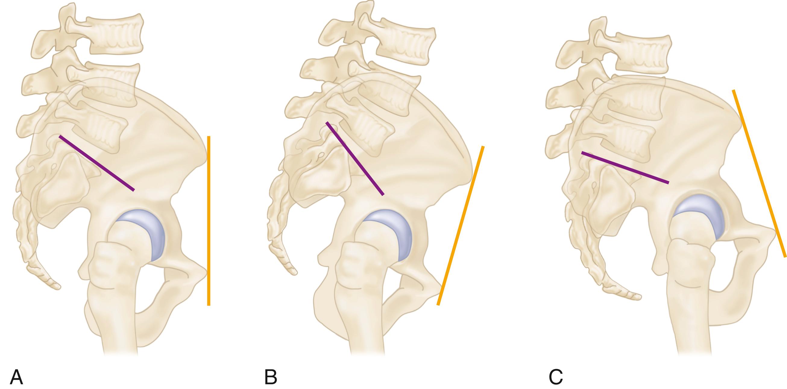
Moving from a standing to sitting position normally results in posterior pelvic tilt with a concomitant reduction in lumbar lordosis and flattening of SS ( Fig. 3.40 ). The normal change in SS from standing to sitting is between 11 and 30 degrees. Spinopelvic stiffness is defined as a change in SS of ≤10 degrees. When this is the case, the hip joint must flex further to assume a seated position, with a greater risk of anterior impingement ( Fig. 3.41 ). In these patients, more anteversion of the acetabular component will be needed to compensate for the reduced posterior pelvic tilt imposed by the stiff spine .
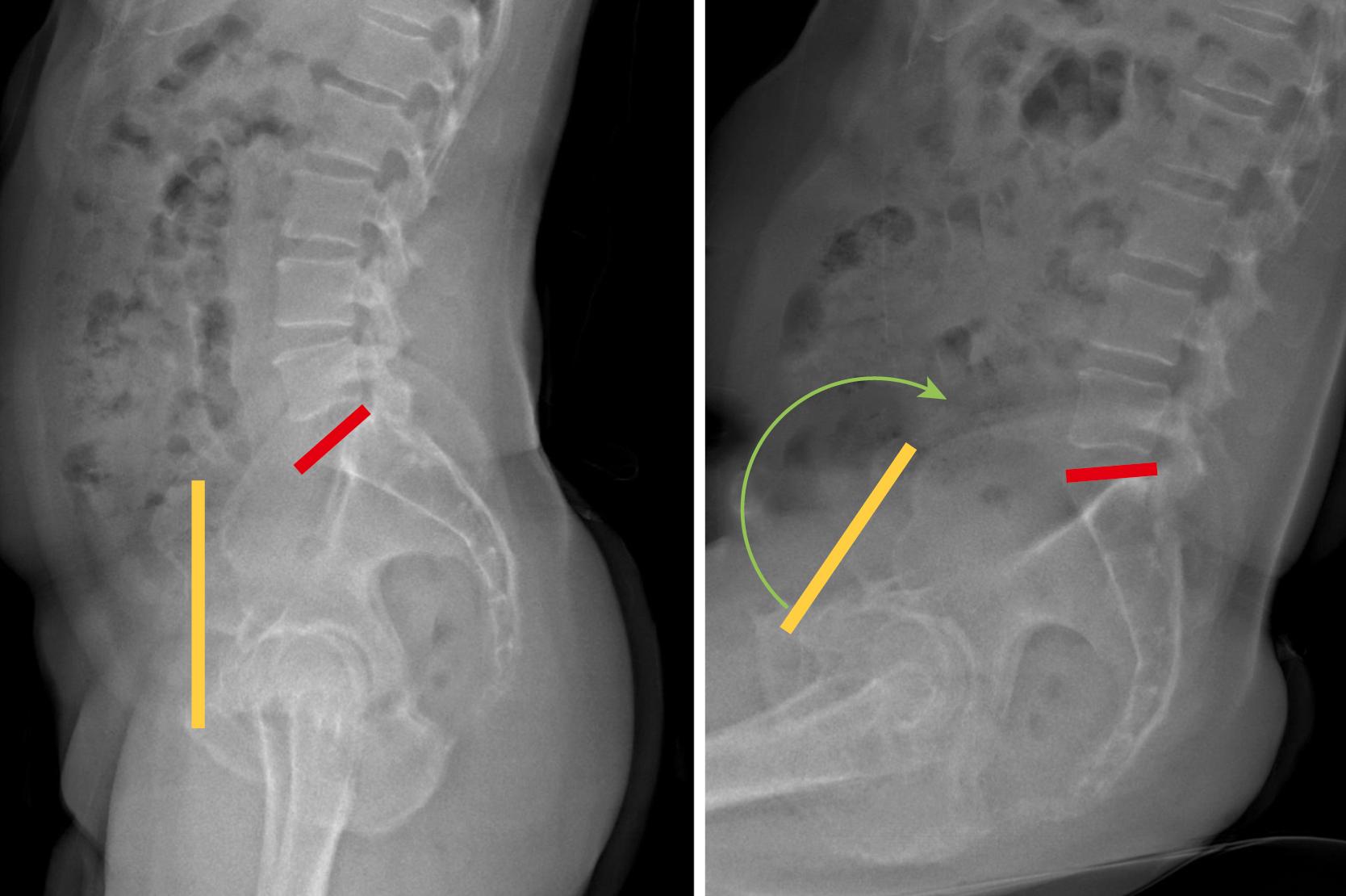
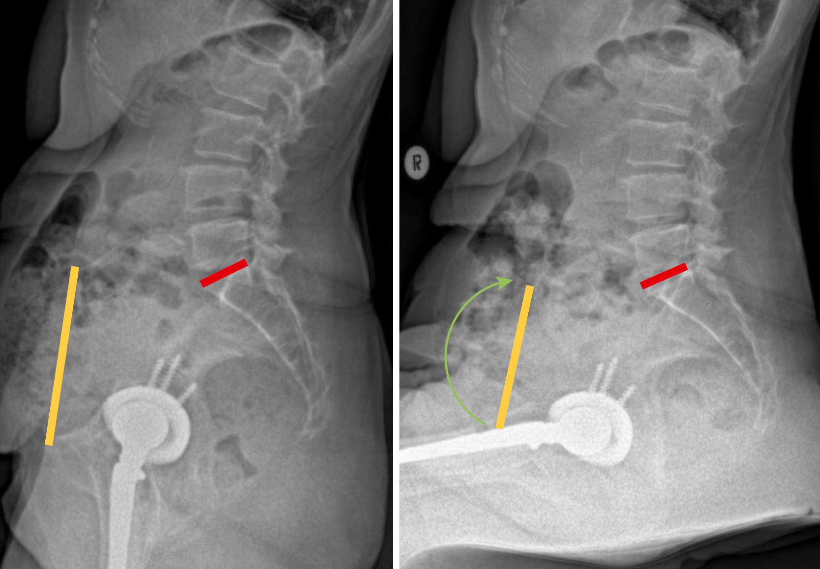
The term pelvic incidence (PI) refers to the angle between a line drawn from the center of the femoral heads to the center of the superior endplate of S1 and a second line drawn perpendicular to the S1 endplate ( Fig. 3.42 ). It is a measurement of the anterior to posterior relationship of the femoral head to the lower lumbar spine. PI is a fixed value and does not change with posture. When combined with measures of the lumbar lordosis (typically the angle between superior endplates of L1 and S1), it may identify patients with a flatback spinal deformity. These patients may have excessive posterior pelvic tilt while standing. This increases the functional anteversion of the acetabulum upon standing, with resulting risk of anterior instability. Therefore, acetabular component anteversion may need to be reduced in these patients.
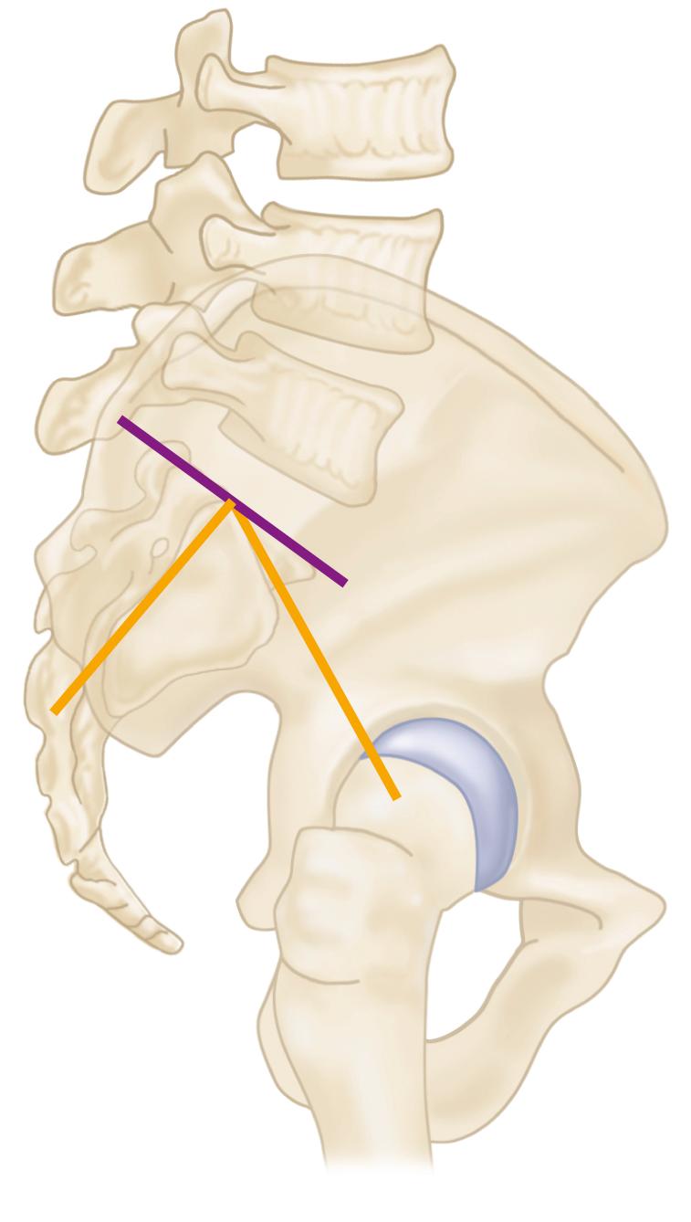
When patients have alterations in spinopelvic mechanics, the so-called safe zone for acetabular component position can be altered in terms of anteversion and also significantly narrowed. In addition to adjustments in implant positioning, dual mobility components (see Fig. 3.35 ) have proven useful in reducing the rate of instability. Innovative new modalities such as EOS imaging (EOS Imaging, Paris) may also simplify the evaluation of these complex cases.
An operating table that tilts easily is recommended, especially if the patient is placed in the lateral position. If the patient is not anchored securely, the proper position in which to place the acetabular component is difficult to determine. A variety of pelvic positioning devices are commercially available for this purpose. Positioning devices should be placed so as not to impede the motion of the hip intraoperatively; otherwise, assessing stability is difficult. Also, the positioning devices should be placed against the pubic symphysis or the ASIS so that no pressure is applied over the femoral triangles, or limb ischemia or compression neuropathy may result. We have previously used suction-deflated beanbags for this purpose. Dedicated hip positioning devices are more secure, but errors in positioning may still occur, even with these devices, resulting in misjudgment of acetabular component anteversion. Bony prominences and the peroneal nerve should be padded, especially if a lengthy procedure is expected. If the patient is to be operated on in the supine position, a small pad is placed beneath the buttock of the affected hip; this is especially helpful in obese patients because it tends to allow the loose adipose tissue to drop away from the site of the incision.
The adhesive edges of a U-shaped plastic drape are applied to the skin to seal off the perineal and gluteal areas, and the hip and entire limb are prepared with a suitable bactericidal solution. The foot preferably is covered with a stockinette, and the final drapes should be of an impervious material to allow abundant irrigation without fear of contaminating the field. If anterior dislocation of the hip is anticipated in the lateral position, a draping system that incorporates a sterile pocket suspended across the anterior side of the operating table is helpful; this allows the leg to be placed in the bag while the femur is being prepared and delivered back onto the table without contaminating the sterile field.
Many variations have evolved in the surgical approaches and techniques used for THA. This is in keeping with the natural tendency of surgeons to individualize operations according to their own clinical and educational experiences. The surgical approaches differ chiefly as to whether the patient is operated on in the lateral or the supine position and whether the hip is dislocated anteriorly or posteriorly.
The choice of specific surgical approach for THA is largely a matter of personal preference and training. The surgical protocol for a given total hip system may advocate a certain approach, as reflected in the technique manual. In reality, virtually all total hip femoral and acetabular components can be properly implanted through numerous approaches, provided that adequate exposure is obtained. Each approach has relative advantages and drawbacks.
The original Charnley technique used the anterolateral surgical approach with the patient supine, osteotomy of the greater trochanter, and anterior dislocation of the hip. This approach is used much less commonly now as a result of problems related to reattachment of the greater trochanter. Amstutz advocated the anterolateral approach with osteotomy of the greater trochanter, but with the patient in the lateral rather than the supine position. The Müller technique also uses the anterolateral approach with the patient in the lateral position but includes release of only the anterior part of the abductor mechanism. The Hardinge direct lateral approach is done with the patient supine or in the lateral position. A muscle-splitting incision through the gluteus medius and minimus allows anterior dislocation of the hip and affords excellent acetabular exposure. Residual abductor weakness and limp after this approach may be the result of avulsion of the repair of the anterior portion of the abductors or of direct injury to the superior gluteal nerve. The Dall variation of this approach involves removal of the anterior portion of the abductors with an attached thin wafer of bone from the anterior edge of the greater trochanter to facilitate their later repair. Abductor function is better after bony reattachment of the anterior portions of these muscles. Head et al. used a modification of the direct lateral approach, in which the patient is in the lateral position and the vastus lateralis is reflected anteriorly in continuity with the anterior cuff of the abductors. This approach allows much greater exposure of the proximal femur than the Hardinge approach, and is more appropriate for revision surgery. Keggi described a supine anterior approach through the medial border of the tensor fascia lata (TFL) muscle; variations of this approach have become popular recently and are advocated for a reduced risk of posterior dislocation. Femoral exposure is more difficult through this so-called direct anterior approach, and injury to the lateral femoral cutaneous nerve (LFCN) can be problematic. The posterolateral approach with posterior dislocation of the hip requires placing the patient in the lateral position and has proven satisfactory for primary and revision surgery. Exposure of the anterior aspect of the acetabulum can be difficult, and historically the postoperative dislocation rate is higher with the posterolateral approach than with the anterolateral or direct lateral approaches.
The specific technique for implantation of a given total hip system varies according to the method of skeletal fixation; the preparation for ancillary fixation devices for the acetabulum; the shape of the femoral component; the length of the stem; and the assembly of modular portions of the acetabular component, the femoral head, and, with some systems, the femoral component itself. The instrumentation supplied with a system is specific for that system and always should be used. The manufacturer supplies a technique manual with the system that gives a precise description of the instruments and the manner in which they are to be used for correct implantation of the components. Although instruments in various systems serve similar purposes, there may be substantial differences in their configurations and in the way they are assembled and used. The surgeon and scrub nurse should become thoroughly familiar with all of the instrumentation before proceeding with the operative procedure. A practice session with plastic bone models or a cadaver is useful before using a new prosthesis for the first time.
Considering the number of total hip systems in current use, this text cannot discuss the particular points of all or any one of them. A general technical guideline is presented for exposure and insertion of cemented and cementless femoral and acetabular components, along with points germane to many types of implants. Additional steps are required for preparation and insertion of certain implants, and the manufacturer’s technique must always be followed in these instances. The techniques presented here are for the posterior and direct anterior approaches; the preparation of the femur and acetabulum is similar for other approaches (see Chapter 1 ). A traditional approach is presented here. Although a less extensile exposure may be appropriate in most cases (see section “Minimally Invasive Techniques”), it is important for surgeons to understand the full array of soft-tissue releases that may be needed in stiff hips and more complex procedures.
The posterolateral approach is a modification of posterior approaches described by Gibson and by Moore (see Chapter 1 ). The approach can be extended proximally by osteotomy of the greater trochanter with anterior dislocation of the hip (see section on trochanteric osteotomy). The approach can be extended distally to allow a posterolateral approach to the entire femoral shaft. We use the posterolateral approach for primary and revision THA.
With the patient firmly anchored in the straight lateral position, make a slightly curved incision centered over the greater trochanter. Begin the skin incision proximally at a point level with the ASIS along a line parallel to the posterior edge of the greater trochanter. Extend the incision distally to the center of the greater trochanter and along the course of the femoral shaft to a point 10 cm distal to the greater trochanter ( Fig. 3.43A ). Adequate extension of the upper portion of the incision is required for reaming of the femoral canal from a superior direction, and the distal extent of the exposure is required for preparation and insertion of the acetabular component from an anteroinferior direction.
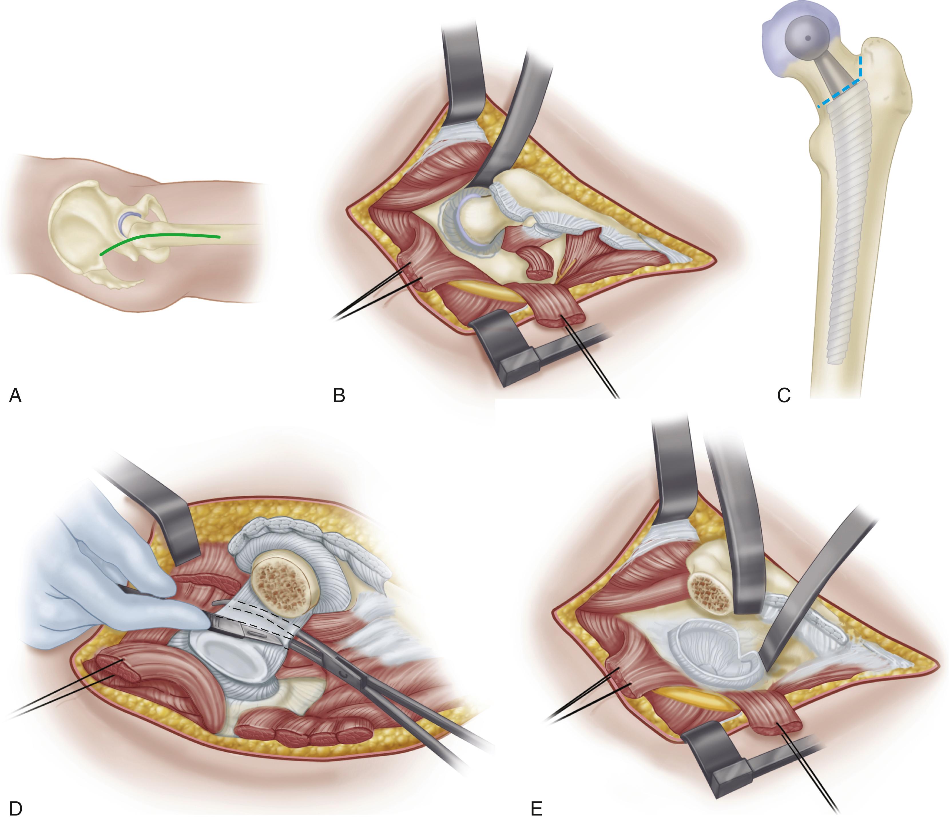
Divide the subcutaneous tissues along the skin incision in a single plane down to the fascia lata and the thin fascia covering the gluteus maximus superiorly.
Dissect the subcutaneous tissues from the fascial plane for approximately 1 cm anteriorly and posteriorly to make identification of this plane easier at the time of closure.
Divide the fascia in line with the skin wound over the center of the greater trochanter.
Bluntly split the gluteus maximus proximally in the direction of its fibers and coagulate any vessels within the substance of the muscle.
Extend the fascial incision distally far enough to expose the tendinous insertion of the gluteus maximus on the posterior femur.
Bluntly dissect the anterior and posterior edges of the fascia from any underlying fibers of the gluteus medius that insert into the undersurface of this fascia. Suture moist towels or laparotomy sponges to the fascial edges anteriorly and posteriorly to exclude the skin, prevent desiccation of the subcutaneous tissues, and collect cement and bone debris generated during the operation.
Insert a Charnley or similar large self-retaining retractor beneath the fascia lata at the level of the trochanter. Take care not to entrap the sciatic nerve beneath the retractor posteriorly.
Divide the trochanteric bursa and bluntly sweep it posteriorly to expose the short external rotators and the posterior edge of the gluteus medius. The posterior border of the gluteus medius is almost in line with the femoral shaft, and the anterior border fans anteriorly.
Maintain the hip in extension as the posterior dissection is done. Flex the knee and internally rotate the extended hip to place the short external rotators under tension.
Palpate the sciatic nerve as it passes superficial to the obturator internus and the gemelli. Complete exposure of the nerve is unnecessary unless the anatomy of the hip joint is distorted.
Palpate the tendinous insertions of the piriformis and obturator internus and place tag sutures in the tendons for later identification at the time of closure.
Divide the short external rotators, including at least the proximal half of the quadratus femoris, as close to their insertion on the femur as possible. Maintaining length of the short rotators facilitates their later repair. Coagulate vessels located along the piriformis tendon and terminal branches of the medial circumflex artery located within the substance of the quadratus femoris. Reflect the short external rotators posteriorly, protecting the sciatic nerve.
Bluntly dissect the interval between the gluteus minimus and the superior capsule. Insert blunt cobra or Hohmann retractors superiorly and inferiorly to obtain exposure of the entire superior, posterior, and inferior portions of the capsule.
Divide the entire exposed portion of the capsule immediately adjacent to its femoral attachment. Retract the capsule and preserve it for later repair ( Fig. 3.43B ).
To determine leg length, insert a Steinmann pin into the ilium superior to the acetabulum and make a mark at a fixed point on the greater trochanter. Measure and record the distance between these two points to determine correct limb length after trial components have been inserted. Make all subsequent measurements with the limb in the identical position. Minor changes in abduction of the hip can produce apparent changes in leg-length measurements. We currently use a device that enables the measurements of leg length and offset ( Fig. 3.44 ).
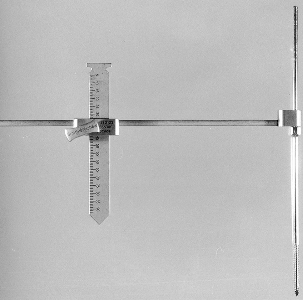
Dislocate the hip posteriorly by flexing, adducting, and gently internally rotating the hip.
Place a bone hook beneath the femoral neck at the level of the lesser trochanter to lift the head gently out of the acetabulum. The ligamentum teres usually is avulsed from the femoral head during dislocation. In younger patients, however, it may require division before the femoral head can be delivered into the wound.
If the hip cannot be easily dislocated, do not forcibly internally rotate the femur because this can cause a fracture of the shaft. Instead, ensure that the superior and inferior portions of the capsule have been released as far anteriorly as possible. Remove any osteophytes along the posterior rim of the acetabulum that may be incarcerating the femoral head. If the hip still cannot be dislocated without undue force (most often encountered with protrusio deformity), divide the femoral neck with an oscillating saw at the appropriate level and subsequently remove the femoral head segment with a corkscrew or divide it into several pieces.
After dislocation of the hip, deliver the proximal femur into the wound with a broad, flat retractor.
Excise residual soft tissue along the intertrochanteric line and expose the upper edge of the lesser trochanter.
Mark the level and angle of the proposed osteotomy of the femoral neck with the electrocautery or with a shallow cut with an osteotome. Many systems have a specific instrument for this purpose. If not, plan the osteotomy by using a trial prosthesis (see Fig. 3.43C ). Use the stem size and neck length trials determined by preoperative templating.
Align the trial stem with the center of the femoral shaft and match the center of the trial femoral head with that of the patient. The level of the neck cut should be the same distance from the top of the lesser trochanter as determined by preoperative templating.
Perform the osteotomy with an oscillating or a reciprocating power saw. If this cut passes below the junction of the lateral aspect of the neck and greater trochanter, a separate longitudinal lateral cut is required. Avoid notching the greater trochanter at the junction of these two cuts because this may predispose to fracture of the trochanter.
Remove the femoral head from the wound by dividing any remaining soft-tissue attachments. Keep the head on the sterile field because it may be needed as a source of bone graft.
Isolate the anterior capsule by passing a curved clamp within the sheath of the psoas tendon.
Retract the femur anteriorly with a bone hook to place the capsule under tension.
Carefully divide the anterior capsule between the jaws of the clamp ( Fig. 3.43D ).
Place a curved cobra or Hohmann retractor in the interval between the anterior rim of the acetabulum and the psoas tendon ( Fig. 3.43E ). Erroneous placement of this retractor over the psoas muscle can cause injury to the femoral nerve or adjacent vessels. The risk increases with a more inferior placement of the retractor. The safest position is near the level of the anterosuperior iliac spine. Place an additional retractor beneath the transverse acetabular ligament to provide inferior exposure.
Retract the posterior soft tissues with a right-angle retractor placed on top of a laparotomy sponge to avoid compression or excessive traction on the sciatic nerve. As an alternative, place Steinmann pins or spike retractors into the posterior column. Avoid impaling the sciatic nerve or placing the pins within the acetabulum, where they would interfere with acetabular preparation.
Retract the femur anteriorly and medially and rotate it slightly to determine which position provides the best acetabular exposure. If after complete capsulotomy the femur cannot be fully retracted anteriorly, divide the tendinous insertion of the gluteus maximus, leaving a 1-cm cuff of tendon on the femur for subsequent reattachment.
Complete the excision of the labrum. Draw the soft tissues into the acetabulum and divide them immediately adjacent to the acetabular rim. Keep the knife blade within the confines of the acetabulum at all times to avoid injury to important structures anteriorly and posteriorly.
Expose the bony margins of the rim of the acetabulum around its entire circumference to facilitate proper placement of the acetabular component.
Use an osteotome to remove any osteophytes that protrude beyond the bony limits of the true acetabulum.
Begin the bony preparation of the acetabulum. The procedure for cartilage removal and reaming of the acetabulum is similar for cementless and cemented acetabular components.
Excise the ligamentum teres and curet any remaining soft tissue from the region of the pulvinar. Brisk bleeding from branches of the obturator artery may be encountered during this maneuver and require cauterization.
Palpate the floor of the acetabulum within the cotyloid notch. Occasionally, hypertrophic osteophytes completely cover the notch and prevent assessment of the location of the medial wall. Remove the osteophytes with osteotomes and rongeurs to locate the medial wall. Otherwise, the acetabular component can be placed in an excessively lateralized position.
Prepare the acetabulum with power reamers ( Fig. 3.45 ). Begin with a reamer smaller than the anticipated final size and direct it medially down to, but not through, the medial wall. Make frequent checks of the depth of reaming to ensure that the medial wall is not violated. This allows a few millimeters of deepening of the acetabulum with improved lateral coverage of the component.
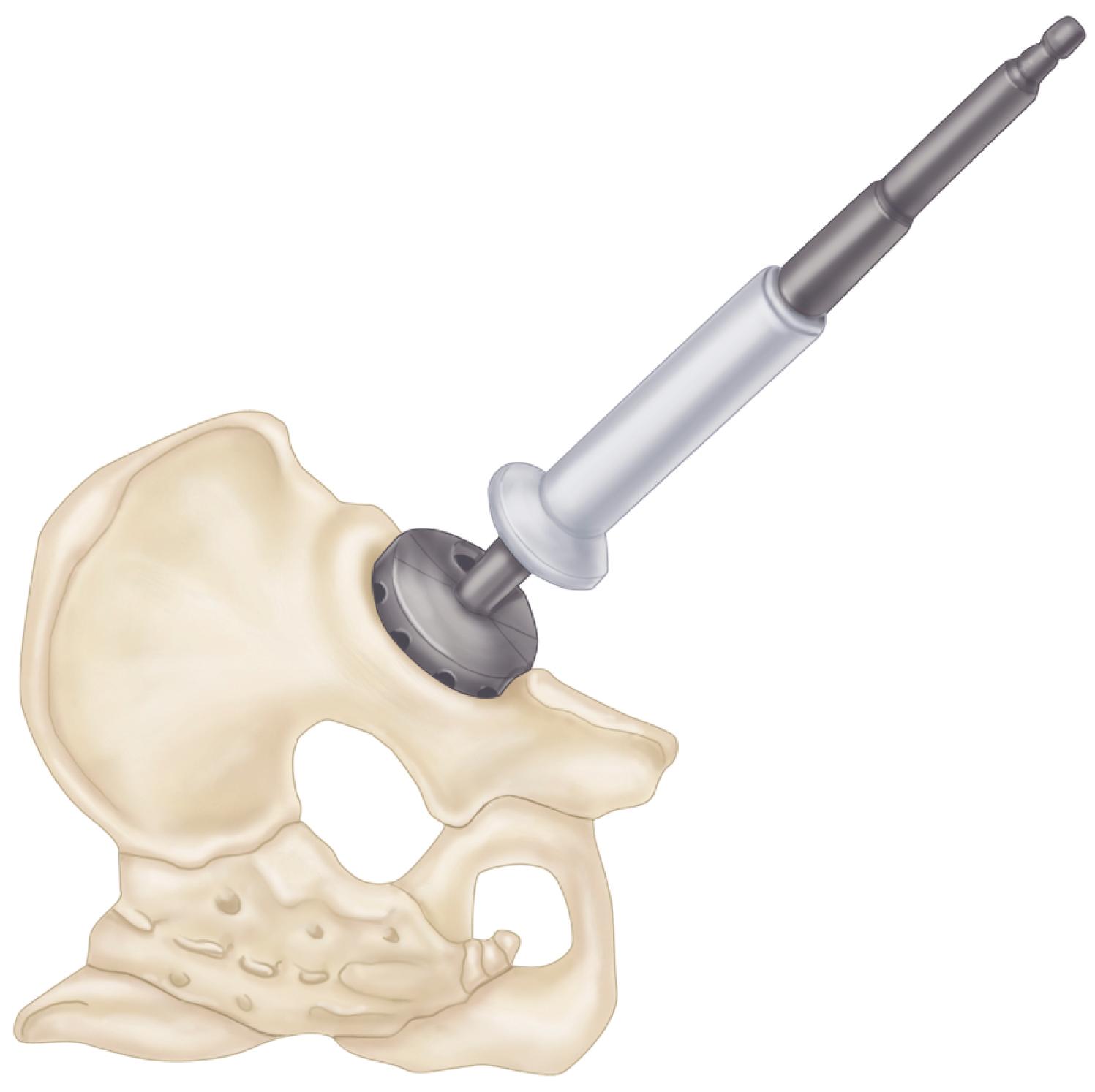
Direct all subsequent reamers in the same plane as the opening face of the acetabulum.
Retract the femur well anteriorly so that reamers can be inserted from an anteroinferior direction without impingement. If the femur is inadequately retracted anteriorly, it may force reamers posteriorly, and excessive reaming of the posterior column occurs. Use progressively larger reamers in 1- or 2-mm increments.
Irrigate the acetabulum frequently to assess the adequacy of reaming and to adjust the direction of the reaming to ensure that circumferential reaming occurs. Reaming is complete when all cartilage has been removed, the reamers have cut bone out to the periphery of the acetabulum, and a hemispherical shape has been produced.
Expose a bleeding subchondral bone bed but maintain as much of the subchondral bone plate as possible.
Curet any remaining soft tissue from the floor of the acetabulum and excise any overhanging soft tissues around the periphery of the acetabulum. Search for subchondral cysts within the acetabulum and remove their contents with small curved curets.
Fill the cavities with morselized cancellous bone obtained from the patient’s femoral head or acetabular reamings and impact the graft with a small punch.
Before insertion of the acetabular component, ensure that the patient remains in the true lateral position. If the pelvis has been rotated anteriorly by forceful anterior retraction of the femur, the acetabular component can easily be placed in a retroverted position, which may predispose to postoperative dislocation. Most systems have trial acetabular components that can be inserted before final implant selection to determine the adequacy of fit, the presence of circumferential bone contact, and the adequacy of the bony coverage of the component; using the trial components also allows the surgeon to make a mental note of the positioning of the component before final implantation.
Proceed with implantation of either a cementless or cemented acetabular component.
The size of the implant is determined by the diameter of the last reamer used. An acetabular component that is the same size as the last reamer has intimate contact with bone but no intrinsic stability. Fixation must be augmented with fins, spikes, or screws. A component that is oversized by 1 to 2 mm can be press-fit into position to provide a greater degree of initial stability. Attempts to impact a much larger component into position results in diminished congruency between the bone and porous surface and incomplete seating of the component against the medial wall. It also might fracture the acetabulum.
Major intrapelvic and extrapelvic vessels and nerves are at risk for injury with erroneously placed transacetabular screws. Wasielewski et al. devised a clinically useful system for determining safe areas for placement of the screws. The system is based on two lines, one drawn from the ASIS through the center of the acetabulum and the other drawn perpendicular to the first, creating four quadrants: anterosuperior, anteroinferior, posterosuperior, and posteroinferior ( Fig. 3.46 ). Screws placed through the anterosuperior quadrant emerge within the pelvis dangerously close to the external iliac artery and vein. Screws passing through the anteroinferior quadrant may injure the obturator nerve and vessels. Screws placed through the posterosuperior and posteroinferior quadrants do not emerge within the pelvis, but they may pass into the sciatic notch and endanger the sciatic nerve and superior gluteal vessels. The drill bit and screw threads can be palpated in the vicinity of the sciatic notch, however, as they emerge so that injury of these structures can be avoided. The posterosuperior quadrant is the safest, and screws longer than 25 mm frequently can be placed through strong bone in this area. The anterosuperior quadrant should be avoided if possible. In a subsequent study, Wasielewski et al. found that only the peripheral halves of the posterior quadrants were safe for screw placement when the acetabular component was implanted with a high hip center.
Place the operating table in a completely level position and ensure that the patient remains in the true lateral position.
Expose the acetabulum circumferentially and retract or excise any redundant soft tissues that may be drawn into the acetabulum as the component is inserted.
Prepare the appropriate recesses for any ancillary fixation devices present on the component as specified by the manufacturer’s technique.
Attach the acetabular component to the positioning device included with the system instrumentation. Be certain of the means by which the positioning device orients the socket. Usually a rod emerging from the positioning device is oriented either parallel or perpendicular to the floor to determine the proper angle of abduction (or inclination) ( Fig. 3.47A ). An additional extension from the alignment device determines anteversion (or forward flexion) in relation to the axis of the trunk of the patient ( Fig. 3.47B ). The optimal inclination of the component is 40 to 45 degrees. The optimal degree of anteversion is 20 degrees.
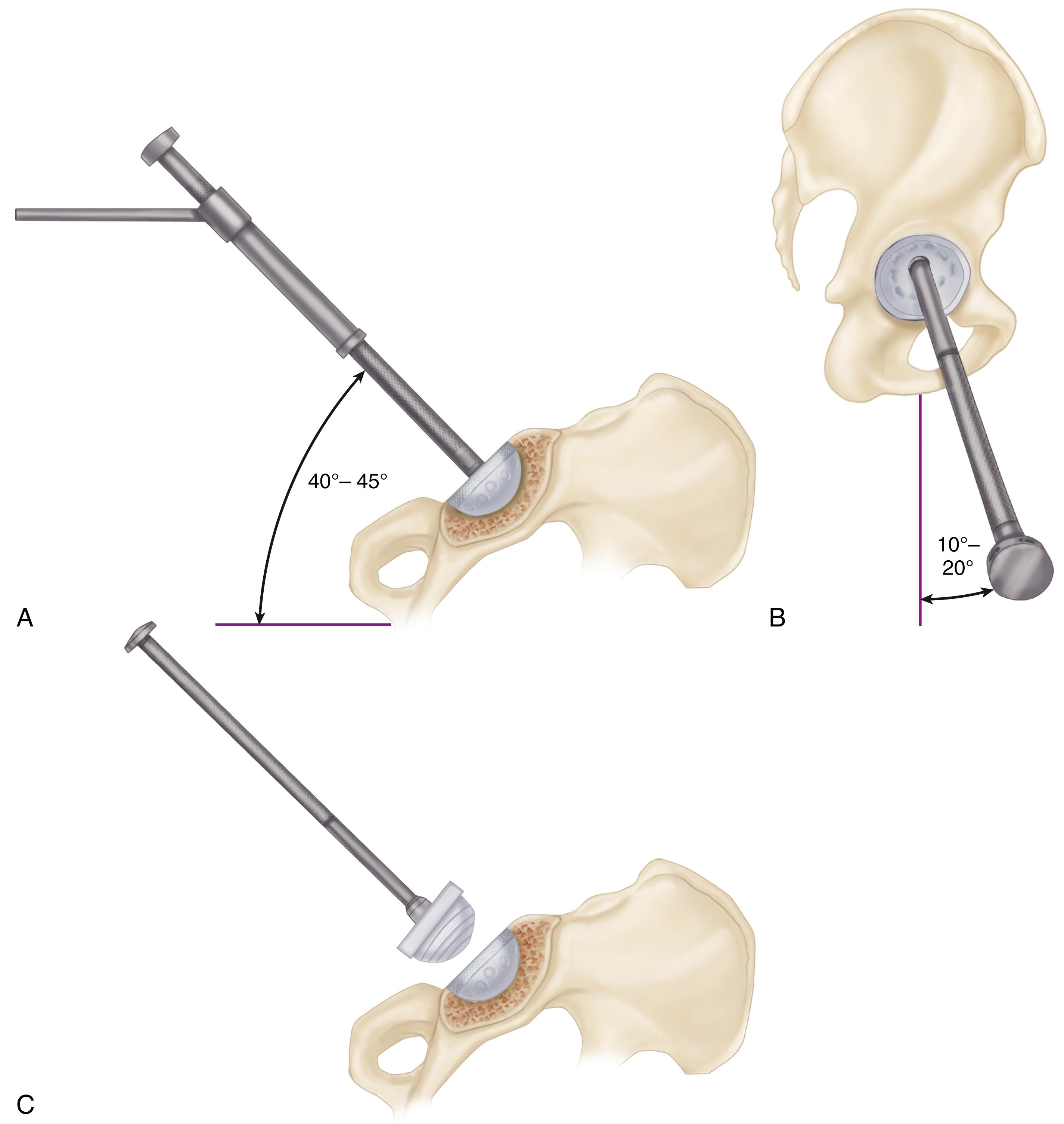
The transverse acetabular ligament also is a useful anatomic reference for component positioning. Place the component parallel and just superior to the ligament.
If the femur demonstrates excessive anteversion or the femoral component is of an anatomic design with anteversion already built in the femoral neck, position the socket in a lesser degree of anteversion. Excessive anteversion of the socket in this case may result in anterior dislocation. Plan for combined anteversion of the femur and acetabulum between 25 and 40 degrees. Carefully reassess the positioning of the implant before impaction because it may be difficult to extricate or change if malpositioned. The edges of the component should match the position of the trial implant fairly closely. If they do not, carefully reassess the positioning of the patient and the insertion device.
Maintain the alignment of the positioning device as the component is impacted into position. A change in pitch is heard as the implant seats against subchondral bone. Reassess the positioning; if it is satisfactory, remove the positioning device.
Examine the subchondral bone plate through any available holes in the component to confirm intimate contact between implant and bone. If a gap is present, impact the component further.
If screws are to be used for ancillary fixation, place them preferably in the posterosuperior quadrant. Use a flexible drill bit and a screwdriver with a universal joint to insert the screws from within the metal shell. Use a drill sleeve to center the drill hole within the hole of the metal shell. If the drill hole is placed eccentrically or at too steep an angle, as the screw is inserted its threads may engage the edge of the hole in the metal shell and lift it away from the bone as the screw is advanced; this requires repositioning and reimpaction of the implant. Additionally, if a screw is placed eccentrically, the edge of the head may sit proud within the screw hole and prevent insertion of the liner. Bicortical purchase usually can be obtained with screws in the posterior quadrants.
Confirm screw length with an angled depth gauge. Self-tapping 6.5-mm screws are preferred. Use a screw-holding clamp to maintain alignment of the screw as the self-tapping threads become engaged. Screw alignment cannot be maintained by a screwdriver with a universal joint. Ensure that the screw head seats completely and is recessed below the inner surface of the shell so that the liner can be fully seated.
If screws are inserted in the posterior quadrants, palpate along the posterior wall and place a finger within the sciatic notch to protect the sciatic nerve.
If the drill bit exits in close proximity to the sciatic nerve, use a screw slightly shorter than the measured length or choose a different hole.
After insertion of one or two screws, test the stability of the component. There should be no detectable motion between implant and bone. If the fixation is unstable, place additional screws.
With a curved osteotome, remove any osteophytes that protrude beyond the rim of the acetabular component. Pay particular attention to the anteroinferior rim. Retained osteophytes in this region cause impingement on the femur in flexion and internal rotation, reducing motion and predisposing to dislocation.
Irrigate any debris from within the metal shell.
Insert the polyethylene liner ensuring that no soft tissue becomes interposed between the polyethylene liner and its metal backing because this would prevent complete seating and engagement of the locking mechanism ( Fig. 3.47C ). If the system has a variety of liner options available (see Fig. 3.33 ), a set of trial liners usually accompanies the instrumentation. Final selection of the degree of rim elevation and the position of rotation of the offset within the metal shell can be delayed until the time of trial reduction. The center of the offset usually is placed superiorly or posterosuperiorly. Use the smallest offset that provides satisfactory stability.
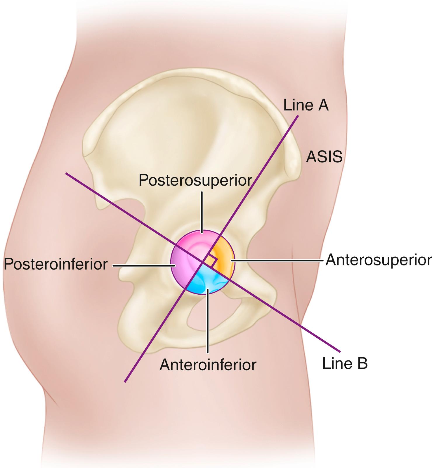
Intraoperative changes in the position of the pelvis can affect the accuracy of orientation of the acetabular component. Abduction of the hip or traction on the limb may rotate the pelvis in the craniocaudal plane and lead to errors in the abduction angle. Forceful anterior retraction of the femur rotates the pelvis forward with the tendency to position the acetabular component with inadequate anteversion if the surgeon relies solely on a positioning guide affixed to the insertion device. The surgeon also should evaluate component position relative to bony landmarks. In the ideal position, the inferior edge of the implant should lie just within and parallel to the transverse ligament. The degree of lateral coverage of the implant should also be compared with the amount estimated by preoperative templating.
The design features of cemented acetabular components are discussed in the earlier section on cemented acetabular components. Many components incorporate numerous preformed PMMA pods that ensure a uniform 3-mm cement mantle (see Fig. 3.31 ). Although some designs incorporate an offset or rim elevation in the polyethylene, the components are not modular and must be inserted as a single unit. The position of rotation of the offset must be selected before cementing the component. All-polyethylene implants usually are available in relatively few sizes. There may be some variability in the thickness of the cement mantle depending on the size of the acetabulum. The size of the implant can be denoted by either the outer diameter of the polyethylene or the outer diameter of the polyethylene plus the additional size provided by the PMMA spacers. Typically, this adds 6 mm to the outer diameter of the implant. The size of the reamed acetabulum should be equal to the outer diameter of the component including the spacers. Otherwise, the component cannot be completely seated.
Place the operating table completely level.
Obtain circumferential exposure of the bony rim of the acetabulum.
Retract the femur well anteriorly to allow unobstructed passage of the implant into the acetabulum.
Check the component positioning device again to be certain of its mechanism for orienting the component in proper position. Also, ensure that the positioner can be easily released from the component such that it does not tend to pull the component away from the cement as it is polymerizing. Use a trial component to evaluate the fit and the bony coverage of the component when placed in the optimal position (see Fig. 3.43 ). Also note the relationship of the edges of the trial component to the bony rim so that this can be reproduced when the final implant is cemented.
Place the implantable component on the positioner so that it is immediately available when the cement is mixed. Do not contaminate the surface of the implant with blood or debris because this would compromise the cement-prosthesis interface.
Drill multiple 6-mm holes through the subchondral bone plate of the ilium and ischium for cement intrusion ( Fig. 3.48 ). As an alternative, 12-mm holes can be drilled in the ilium and ischium with additional 6-mm holes between them. Do not drill through the medial wall because this would allow cement intrusion into the pelvis.
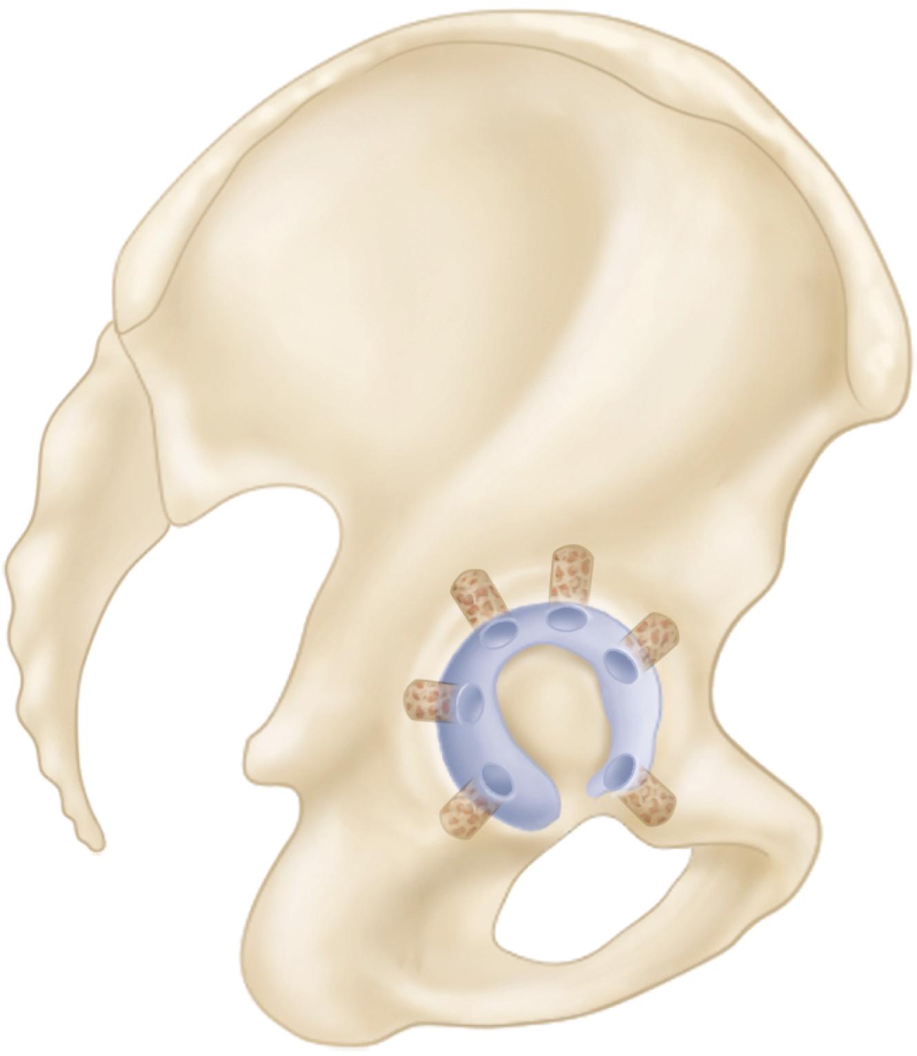
Obturate any penetration of the medial wall with bone grafts or a small wire mesh.
Curet any loose bone from the drill holes and remove debris and bone marrow from the surface of the acetabulum with pulsatile lavage.
Thoroughly dry the acetabulum and promote hemostasis with multiple absorbable gelatin sponge (Gelfoam) pledgets or gauze soaked in topical thrombin or 1:500,000 epinephrine solution.
Mix one package of cement for a smaller patient and two packages for a larger size acetabulum or if an injecting gun is used for cement delivery. Reduce the porosity of the cement by vacuum mixing. Inject the cement in an early dough phase. If the cement is chilled or injected in a very low-viscosity state, it runs out of the acetabulum and pressurization is difficult.
Dry the acetabulum and suction the fixation holes with a small catheter immediately before cement injection. Inject each of the fixation holes first. Use a cement injection nozzle, which has a small occlusive seal that allows pressurization of each of the holes. Fill the remainder of the acetabulum with cement injected from the gun. Pressurize the major portion of the acetabular cement with a rubber impactor ( Fig. 3.49 ).
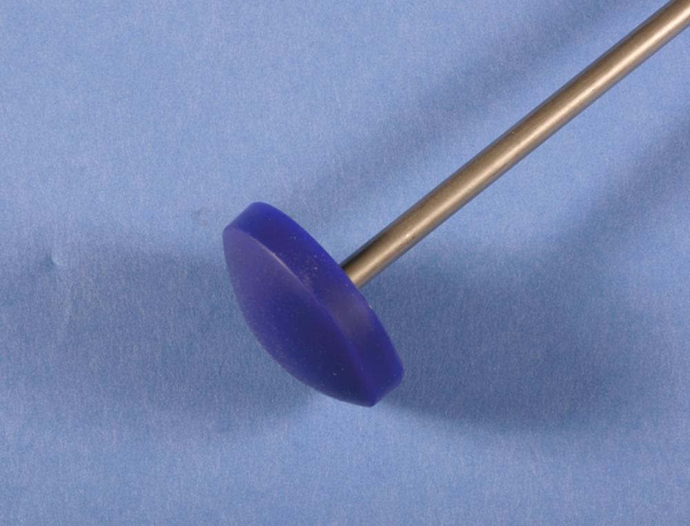
After removing the pressurizing device, carefully dry any blood or fluid that may have accumulated over the surface of the cement.
Some types of cement, such as Palacos, do not pass through a low-viscosity state and are not easily injected through a gun. Such cements may be used in dough form and inserted manually. Change to a new pair of outer gloves before handling the cement. The bolus of cement is placed into the acetabulum after it ceases to stick to the dry gloves and its surface becomes slightly wrinkled.
Finger pack a smaller bolus of cement into each of the previously prepared fixation holes. Distribute the remainder of the cement uniformly over the surface of the acetabulum and pressurize it. Remove any blood on the surface of the cement with a dry sponge.
Insert the acetabular component using the appropriate positioning device. Place the apex of the cup in the center of the cement mass to distribute the cement evenly. Note the relationship of the rim of the component to the bony margins of the acetabulum to verify that the position of the trial component has been reproduced. If no spacers are used, avoid excessive pressure because the cup can be bottomed out against the floor of the acetabulum, producing a discontinuity in the cement mantle.
Hold the positioner motionless as the cement begins to polymerize. When the cement becomes moderately doughy, carefully remove the positioning device. Stabilize the edge of the component with an instrument as the positioner is removed.
Replace the device with a ball-type pusher inserted into the socket to maintain pressure as the cement hardens.
Trim the extruded cement around the edge of the component and remove all cement debris from the area.
After the cement has hardened completely, test the stability of the newly implanted socket by pushing on several points around the circumference with an impactor. If any motion is detected or blood or small bubbles extrude from the interface, the component is loose and must be removed and replaced (see the section on removal of the cup and cement from the acetabulum).
Remove any residual osteophytes or cement projecting beyond the rim of the implant because they may cause impingement and postoperative dislocation.
Long-term outcomes with cemented acetabular components are correlated with the presence of radiolucencies on immediate postoperative radiographs, emphasizing the importance of technique and obtaining a dry bed for cement penetration into cancellous bone.
Place a laparotomy sponge in the depths of the acetabulum to protect the acetabular component and prevent the introduction of debris during preparation and insertion of the femoral component.
Expose the proximal femur by markedly internally rotating the femur so that the tibia is perpendicular to the floor ( Fig. 3.50 ). Allow the knee to drop toward the floor, and push the femur proximally.
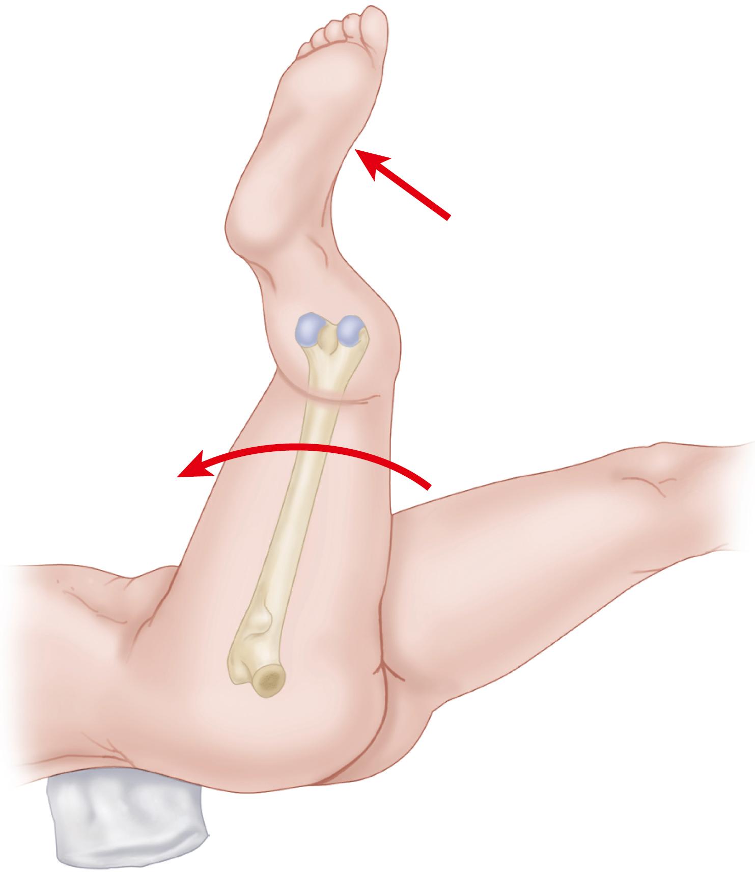
To deliver the proximal femur from the wound, place a broad, flat retractor deep to it and lever it upward. Retract the posterior edge of the gluteus medius and minimus to expose the piriformis fossa and to avoid injuring the former during preparation and insertion of the femoral component.
Excise any remaining soft tissue from the posterior and lateral aspect of the neck. Use a box osteotome or a specialized trochanteric router to remove any remaining portions of the lateral aspect of the femoral neck and the medial portion of the greater trochanter to allow access to the center of the femoral canal ( Fig. 3.51 ).
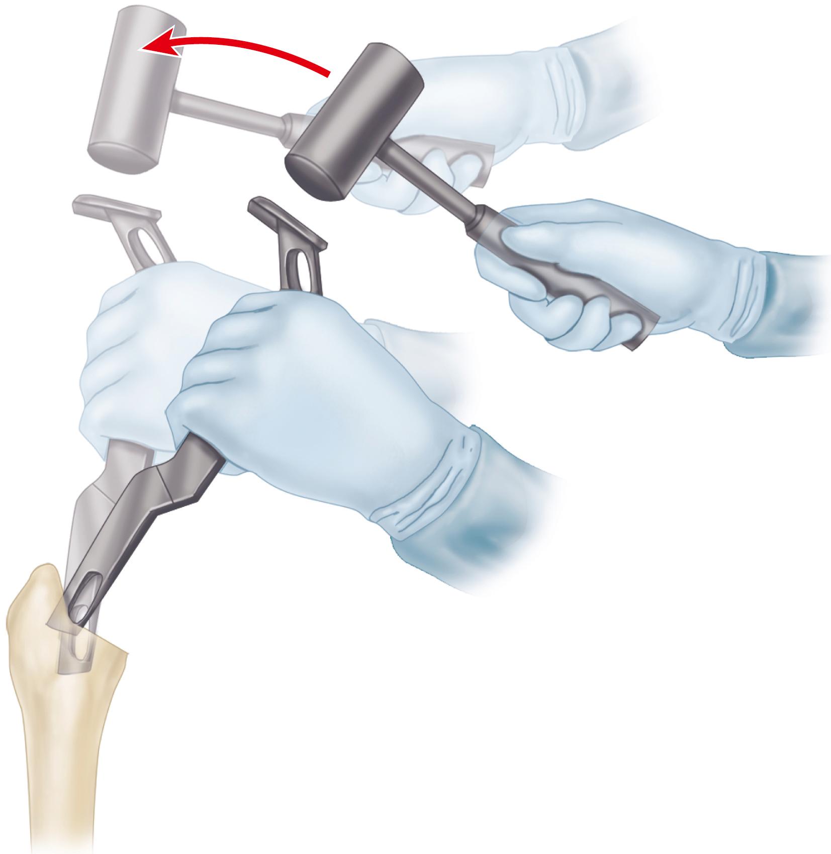
If inadequate bone is removed from these areas, the stem may be placed in varus and may be undersized, the lateral femoral cortex may be perforated, or the femoral shaft or greater trochanter may be fractured.
If the proximal femoral cortex is thin, or if stress risers are present because of previous internal fixation devices or disease, place a cerclage wire around the femur above the level of the lesser trochanter to prevent inadvertent fracture.
The design features of relevant implants are reviewed in the earlier section on cementless femoral components. Younger patients with good quality femoral bone are the best candidates for cementless femoral fixation. Straight femoral components require straight, fully fluted reamers, but anatomic-type components may require femoral preparation with flexible reamers to accommodate the slight curvature of the stem. Some designs of tapered stems require only broaching for canal preparation. Reaming can be done by hand or with low-speed power reamers. Only the instrumentation supplied by the manufacturer should be used to machine the femur to match precisely the femoral stem shape being implanted. The preoperative plan should be reviewed for the anticipated stem size, as determined by templating.
Expose the proximal femur as described in Technique 3.2.
Insert the smallest reamer at a point corresponding to the piriformis fossa. The insertion point is slightly posterior and lateral on the cut surface of the femoral neck. An aberrant insertion point does not allow access to the center of the medullary canal.
After the point of the reamer has been inserted, direct the handle laterally toward the greater trochanter ( Fig. 3.52 ). Aim the reamer down the femur toward the medial femoral condyle. If this cannot be accomplished, remove additional bone from the medial aspect of the greater trochanter, or varus positioning of the femoral component results. Generally, a groove must be made in the medial aspect of the greater trochanter to allow proper axial reaming of the canal. Insert the reamer to a predetermined point. Most reamers are marked so as to be referenced against the tip of the greater trochanter or the femoral neck cut to determine the proper depth of insertion.
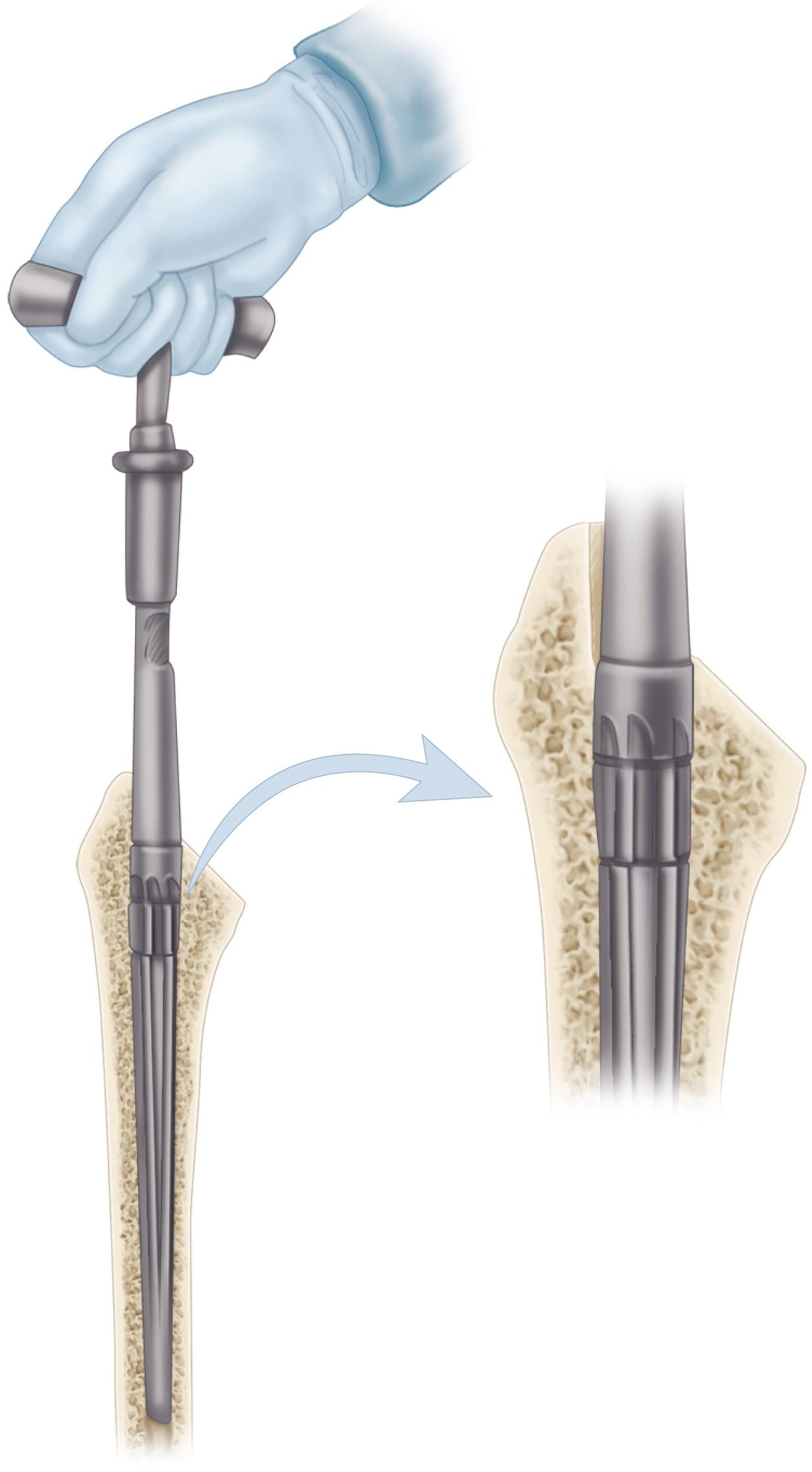
Proceed with progressively larger reamers until diaphyseal cortical reaming is felt. Assess the stability of the axial reamer within the canal. No deflection of the tip of the reamer in any plane should be possible.
If an extensively porous-coated straight stem is used, ream the femoral diaphysis so that 10 to 40 mm of the stem fits tightly in the diaphysis, but underream the canal 0.5 mm smaller than the cylindrical distal portion of the stem so that a tight distal fit can be achieved.
Proceed with preparation of the proximal portion of the femur. Remove the residual cancellous bone along the medial aspect of the neck with precision broaches. Begin with a broach at least two sizes smaller than the anticipated stem. Never use a broach larger than the last straight or flexible reamer used.
Place the broach precisely in the same alignment as the axial reamers.
Push the broach handle laterally during insertion to ensure that enough lateral bone is removed and avoid varus positioning of the stem ( Fig. 3.53 ).
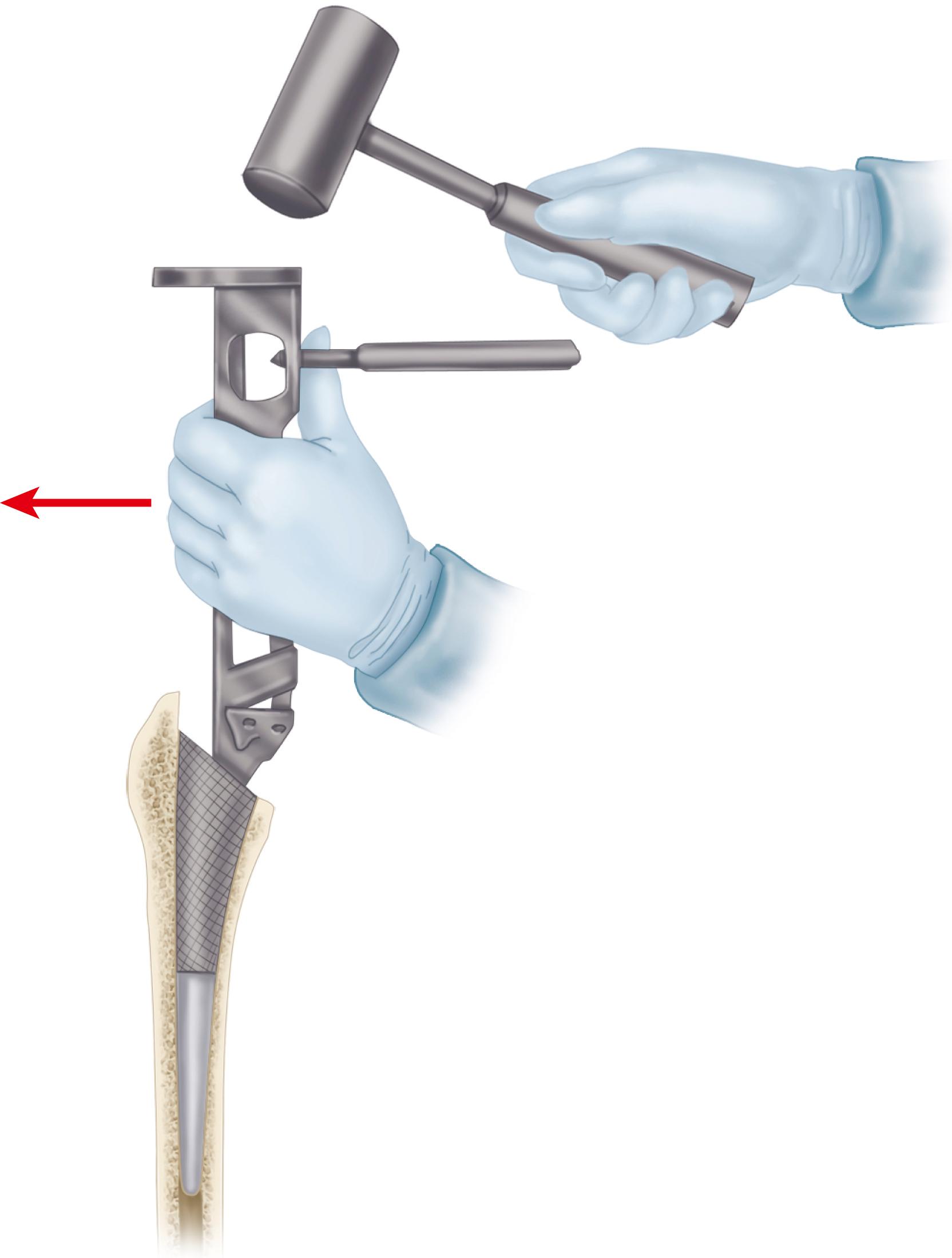
Rotate the broach to control anteversion. From the posterior approach, the medial aspect of the broach must be rotated toward the floor.
Align the broach to match precisely the axis of the patient’s femoral neck. Do not attempt to place the broach in additional anteversion because this would lead to undersizing of the stem and insufficient rotational stability ( Fig. 3.54 ). Maintain precise control over anteversion as the broach is gently impacted down the canal. Seat the cutting teeth of the broach at least to the level of the cut surface of the neck.
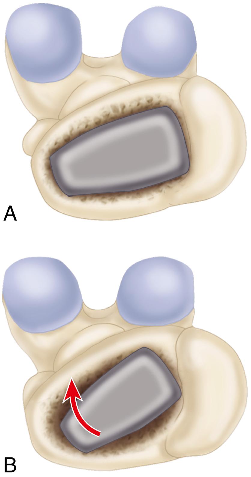
Proceed with progressively larger broaches, maintaining the identical alignment and rotation. Use even blows with a mallet to advance the broach. The broach should advance slightly with each blow of the mallet. If motion ceases, do not use greater force to insert the broach. Reassess the broach size, adequacy of distal reaming, and alignment and rotation of the broach.
If a broach sized smaller than that anticipated by templating cannot be fully inserted, the broach may be in varus. Lateralize farther into the greater trochanter with reamers to achieve neutral alignment in the femoral canal and proceed with broaching.
Seat the final broach to a point where it becomes axially stable within the canal and would not advance farther with even blows of the mallet. The cutting teeth should be seated at or just below the level of the preliminary neck cut to allow precision machining of the remaining neck if a collared stem is to be used.
Assess the fit of the broach within the canal. The broach should be in intimate contact with a large portion of the endosteal cortex, especially posteriorly and medially.
When a straight stem is used, there may be a thin rim of remaining cancellous bone anteriorly. Conversely, an ana tomic stem often fills this area. If the broach seems to fill the canal completely, with little remaining cancellous bone, assess the rotational stability of the broach. Manually attempt to rotate the broach into a retroverted position. Carefully observe the broach for any motion within the femoral canal. If rotational motion is evident, proceed to the next largest stem size. Proceed one size at a time with distal axial reaming and subsequent broaching until the broach fills the proximal femur as completely as possible and adequate axial and rotational stability has been achieved.
When adequate stability has been obtained, make the final adjustment of the neck cut. Most systems have a precision calcar planer that fits onto a trunnion on the implanted broach ( Fig. 3.55 ). Precise preparation of the neck is essential if a collared stem is to be used; this step is optional when a collarless stem design is employed. The final level of the neck cut should correspond with the measured distance above the lesser trochanter determined by preoperative templating. If different, adjust the component neck length accordingly.
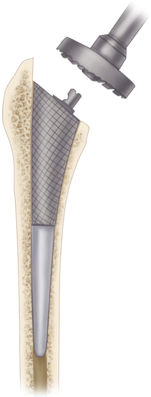
Select the trial neck component determined through preoperative templating. In most systems, the trial head and neck components fit onto the trunnion used for attachment of the broach handle ( Fig. 3.56 ). Evaluate the center of the femoral head relative to the height of the tip of the greater trochanter and compare the level with the templated radiographs.
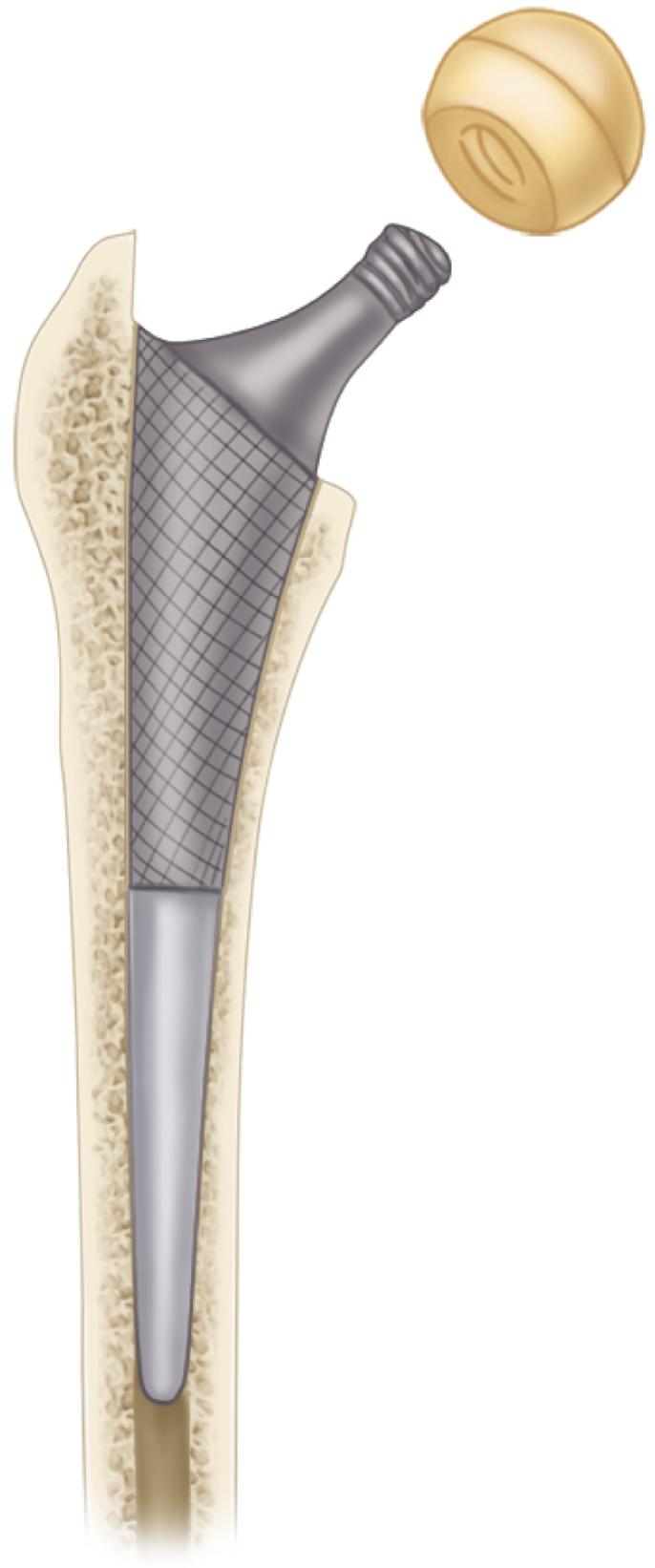
If the neck length seems satisfactory, irrigate any debris out of the acetabulum.
Apply traction to the extremity with the hip in slight flexion. Gently lift the head over the superior lip of the acetabulum and any elevation in the polyethylene liner that may have been inserted. If the reduction is difficult, check for any remaining tight capsule, especially anteriorly, and incise it. If reduction is still impossible, use a shorter neck length, rotate the elevation in the liner to a different position, or remove it entirely.
As an alternative, use a plastic-covered pusher that fits over the head of the femoral component to push the head into the socket. Do not use excessive force or place excessive torsion on the femur as the hip is reduced, or femoral fracture may occur.
Reassess the limb length and femoral offset by the previously placed pin near the acetabulum and make changes accordingly.
Move the hip through a range of motion. Note any areas of impingement between the femur and pelvis or between the prosthetic components with extremes of positioning. Impingement can occur with flexion, adduction, and internal rotation if osteophytes have not been removed from the anterior aspect of the acetabulum, greater trochanter, or femoral neck. Likewise, impingement during external rotation may require removal of bone from the posterior aspect of the greater trochanter, the rim of the acetabulum, or the ischium.
If prosthetic neck impingement occurs on an elevated polyethylene liner, rotate it to a slightly different position or remove it entirely.
The hip should be stable (1) in full extension with 40 degrees of external rotation; (2) in flexion to 90 degrees with at least 45 degrees of internal rotation; and (3) with the hip flexed 40 degrees with adduction and axial loading (the so-called position of sleep). If the hip dislocates easily and the head can be manually distracted from the socket more than a few millimeters (the so-called shuck test), use a longer neck length.
If excessive lengthening of the extremity would result from a longer neck length, use a stem design with a greater degree of offset, if available (see Fig. 3.9 ). This change would reduce bony impingement and improve soft-tissue tension without additional lengthening of the limb. Slight lengthening of the limb is preferable, however, to the risk of instability.
If the hip cannot be brought into full extension, use a shorter neck length, or, if a severe flexion contracture was present preoperatively, release any remaining tight anterior capsular tissues.
If there is uncertainty regarding appropriateness of implant size and position or of limb length, then make an intraoperative radiograph for confirmation.
If stability is acceptable, note the position of any elevation of the trial polyethylene liner, redislocate the hip by flexion and internal rotation, and gently lift the head out of the acetabulum. Remove the trial components and broach.
If a modular trial polyethylene liner has been used, place the final component at this time.
Regain exposure of the proximal femur and remove any loose debris within the femoral canal, but do not disturb the bed that has been prepared.
Insert the appropriate-size femoral component. Insert the stem to within a few centimeters of complete seating by hand. Reproduce the precise degree of anteversion determined by the broach.
Gently impact the stem down the canal. Use the driving device provided with the system or a plastic-tipped pusher. Use blows of equal force as the component is seated. As the component nears complete seating, it advances in smaller increments with each blow of the mallet. Do not use progressively increasing force to insert the component, or femoral fracture can result. Insertion is complete when the stem no longer advances with each blow of the mallet. An audible change in pitch usually can be detected as the stem nears final seating.
Occasionally, it is impossible to seat the prosthesis to the level of the cut surface of the neck. If a collared prosthesis has been used and the collar has not made full contact with bone, leave the collar slightly proud rather than risk femoral fracture. When a collarless prosthesis is used, occasionally the prosthesis may advance a few millimeters past the level achieved with the broach. In these instances, the neck length can be changed and an additional trial reduction is necessary to confirm the final neck length and the stability of the joint.
Test the stability of the implanted stem to rotational and extraction forces. If the stem is deemed unstable, decide whether it can be impacted further or whether a larger stem size can be inserted.
Carefully inspect the femoral neck and greater trochanter for any fractures that may have occurred during stem insertion.
If a fracture is produced as the stem is being seated, immediately stop the insertion procedure. Completely expose the fracture to its distal extent and then remove the stem. Otherwise, the extent of the fracture may be underestimated.
If an incomplete fracture occurs with extension only to the level of the lesser trochanter, place a cerclage wire around the femur above the lesser trochanter. Reinsert the stem and ensure the cerclage wire tightens as the stem is seated into position. Reassess the stability of the implanted stem.
If the fracture extends below the level of the lesser trochanter, a longer stem with greater distal fixation is required (see later). If the greater trochanter is fractured and unstable, proceed with fixation as for a trochanteric osteotomy (see section on trochanteric osteotomy).
Wipe any debris from the Morse taper segment of the prosthetic neck and carefully dry it.
Place the prosthetic head of appropriate size and neck length onto the trunnion and affix it with a single blow of a mallet over a plastic-capped head impactor. Use only femoral heads specifically designed to mate with the stem and ensure that the femoral head and acetabular component are of a corresponding size.
Remove any debris from the acetabulum and again reduce the hip. Ensure no soft tissues have been reduced into the joint.
Confirm the stability of the hip through a functional range of motion.
Improvements in preparation of the femur and the mixing and delivery of cement and modifications in component design have yielded dramatic improvements in the survivorship of cemented femoral components. Cement fixation is indicated especially when the femoral cortex is thin or osteoporotic and secure press-fit fixation is less predictably achieved. Design features of femoral components used with cement are reviewed in the earlier section on femoral stems used with cement.
Expose the proximal femur as described. Use rongeurs, a box osteotome, or a trochanteric reamer to remove residual portions of the lateral aspect of the neck and gain access to the center of the canal.
Insert a small, tapered reamer to locate the medullary canal. Insert the tip of the reamer into the lateralmost aspect of the cut surface of the neck and swing it into the greater trochanter to point it toward the medial femoral condyle (see Fig. 3.52 ). This maneuver ensures neutral positioning of the femoral component.
Review the preoperative plan for the templated stem size. Begin with the smallest size broach. Insert the broaches in 10 to 15 degrees of anteversion in relation to the axis of the flexed tibia. From the posterior approach, this means that the medial aspect of the broach must be rotated toward the floor (see Fig. 3.54 ). Maintain correct axial alignment as the broach is inserted.
Alternatively, impact and extract the broach to facilitate its passage. Use progressively larger broaches to crush and remove cancellous bone in the proximal femur. Because fixation is achieved with cement, the requirements for absolute stability of the broach are not as rigorous as with cementless techniques. Nonetheless, a stem that fills the femoral canal with an adequate cement mantle is still desirable.
Use the largest size broach that can be easily inserted proximally. If resistance is felt during insertion of the broach, the area of impingement is most likely distal within the diaphysis. The broach cannot be used to prepare cortical bone in the diaphysis. Do not attempt to impact the broach further because a femoral fracture can occur, or the broach can become incarcerated.
A narrow canal can be anticipated easily by preoperative templating. Use graduated-sized reamers to enlarge the canal sufficiently to allow insertion of a broach that is appropriately sized proximally. Because removal of all cancellous bone from the canal leaves a smooth cortical surface not amenable to microinterlock with cement, avoid excessive reaming of the medullary canal. Canal preparation is distinctly different with this procedure than for a cementless stem, even though many contemporary total hip systems use the same instrumentation for the two applications.
In most current systems, the broach is larger than the corresponding stem size, although the amount of oversizing varies. The channel prepared allows insertion of an appropriate-size stem with an adequate surrounding cement mantle. A cement mantle thickness of 2 to 4 mm proximally and 2 mm distally is satisfactory.
If a stem with a collar is to be used, countersink the final broach slightly below the provisional femoral neck cut. Precisely prepare the femoral neck to receive the collar by using a planer (see Fig. 3.55 ). If a collarless stem is used, mark the height of the shoulder of the broach on the greater trochanter in order to reproduce this position when the final stem is implanted.
Select the templated neck length and assemble a trial component. Note the relationship of the trial collar to the cut surface of the femoral neck for axial and rotational positioning of the final stem as it is implanted. The medial edge of the collar may sit flush with the medial cortex or may protrude slightly beyond it; either is acceptable. Reproduction of this degree of overhang helps prevent varus or valgus positioning of the stem as the final component is inserted.
Perform a trial reduction, as described in Technique 3.5, to determine limb length, range of motion, and stability of the arthroplasty.
If the limb has been excessively lengthened, use a shorter trial neck. Alternatively, seat the broach further and recut the femoral neck to reduce limb length while maintaining the same degree of femoral offset. A smaller broach size may be required to accomplish this.
Because the stem is to be fixed with cement, the depth of insertion of the component is predetermined at this point. This is in contrast to a cementless implant, which may achieve stability at a slightly different depth of insertion than did the corresponding broach.
When final component sizes have been selected and limb length and stability have been assessed, dislocate the hip and remove the trial components.
Regain exposure of the proximal femur.
Remove remaining loose cancellous bone from the femur using a femoral canal brush or curets. Retain a few millimeters of dense cancellous bone for cement intrusion.
Occlude the femoral canal distal to the anticipated tip of the stem to allow pressurization of the cement and to prevent extrusion of the cement distally into the femoral diaphysis. This is accomplished by use of a plastic, flexible canal plug or a bone block fashioned to fit the canal or by injecting a small plug of cement distally. A preformed flexible plastic plug is the easiest to use, but it must be of a large enough size to prevent its distal migration during cement pressurization ( Fig. 3.57 ).
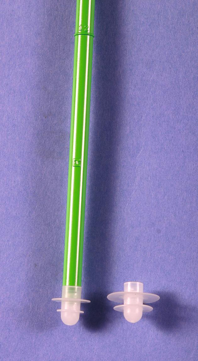
Determine the canal diameter by using sounds. Insert the cement restrictor to a depth of approximately 1 to 2 cm below the anticipated tip of the stem. Determine the depth of insertion by comparing the insertion device with the broach or the actual stem. Account for any additional length required by the use of a distal stem centralizer. Gently tap the restrictor into place, or it may be forced distal to the isthmus.
After insertion of the cement restrictor, reinsert the broach or trial stem to ensure that the restrictor has been placed sufficiently distal to allow the stem to be fully seated.
As an alternative, fashion a plug of bone removed from the femoral head or neck. This plug should be slightly larger than the diameter of the canal. Impact it into position with a punch.
Occlusion of the canal with a small bolus of PMMA requires more preparation but is more reliable when the canal is excessively large or when the canal must be occluded below the level of the isthmus to insert a longer length stem. To occlude the canal with a PMMA plug, mix a single package of cement. Insert the cement when it is in the early dough phase because extremely low-viscosity cement runs down the canal and does not completely occlude it. Inject a small bolus of cement at the prede termined level using a cement injecting gun or a cement syringe, or introduce the cement through a small chest tube, using a plunger to maintain the cement bolus in proper position as the chest tube is extracted. Rotate the injecting gun in all directions to disperse the cement uniformly. Reinsert the trial component and gently tamp the cement before it hardens to ensure that the final component can be fully seated.
After occluding the femoral canal, thoroughly irrigate it to remove loose debris, bone marrow, and blood. This is best accomplished by using a pulsatile lavage system with a long, straight tip and radially directed spray. Thoroughly irrigate all debris and bone marrow out of the residual trabeculae of cancellous bone so that maximal cement intrusion can be obtained. Thorough lavage of the canal also reduces the amount of marrow embolization that can occur during cement pressurization and stem insertion.
Dry the canal with a tampon sponge with a suction attachment or with sponges soaked in 1:500,000 epinephrine solution to diminish bleeding while the cement is being prepared.
Open the previously determined implants. Do not touch the stem or allow it to become contaminated with blood or debris because this may compromise the cement-implant interface after implantation.
Assemble any modular PMMA spacers that can be used to centralize the stem within the canal.
Do not leave unfilled any holes in the stem intended for centralizers because entrapped air would expand with the heat of cement polymerization, producing a void in the cement mantle. Fill such holes with cement before introducing the implant, or use the centralizers provided with the system. Centralizers also can be fixed to the implant with a small amount of cement to ensure an adequate interface between the two. This distal stem centralizer size is determined by the canal diameter previously determined from sounds. Ideally, the centralizer should be at least 4 mm larger than the diameter of the distal end of the stem to ensure a 2-mm circumferential cement mantle.
Change the outer gloves. Mix two batches of cement for a standard-size femur and three batches for a larger femur or if a long-stem component is to be used. Current pressurization techniques require a greater volume of cement than has been used in the past. Prepare the cement with a porosity reduction technique such as vacuum mixing.
If internal fixation devices have been removed from the femoral shaft during the same procedure, the holes left in the femoral cortex must be occluded to allow pressurization of the cement and to prevent its egress into the soft tissues. Have an assistant place fingers over the holes before cement injection, or use a small amount of cement to occlude them before the remainder of the femur is filled with cement.
Use a cement-injecting gun for the most reliable cement delivery. Plan to inject the cement as it enters a dough phase, or when it no longer sticks to a gloved finger. This typically is about 4 minutes after the start of mixing for Simplex cement, although it can vary significantly with the type of cement used, the room temperature, humidity, and whether the monomer component or stem was heated before mixing. If the cement is injected in an excessively low-viscosity state, it tends to run out of the femur during pressurization, making it more susceptible to the introduction of blood and debris, thus weakening the mantle and compromising the cement-bone interface. If injected late or in a high viscosity state, then it may be difficult to fully insert the stem before cement polymerization occurs.
Pack a sponge within the acetabulum and shield the surrounding soft tissues with sponges to prevent the escape of cement.
Immediately before introduction of the cement injecting gun, remove any packing sponges and suction the distal aspect of the canal to remove any blood that has pooled there.
Pump the trigger of the cement injecting gun to deliver cement to the tip of the nozzle so that no air is introduced. Insert the nozzle to the level of the cement restrictor, and use smooth, sequential compressions of the trigger to deliver the cement in a uniform manner ( Fig. 3.58 ). Allow the pressure of the injected cement to push the nozzle out of the canal as the canal is filled in a retrograde fashion. Do not pull the nozzle back too quickly or voids would be created in the cement column. Fill the canal to the level of the cut surface of the femoral neck.

Pressurize the cement by one of many methods. Preferably, use an occlusive nozzle that allows the injection of more cement through it ( Fig. 3.59 ). Ensure that an adequate seal is maintained and slowly inject more cement over approximately 30 seconds to produce intrusion of cement into remaining cancellous bone bed. As an alternative, use a plastic impactor or mechanical plunger-type device placed over a glove or rubber sheet. Cement and bone marrow can be seen extruding from the small vascular foramina along the femoral neck during pressurization.

Remove the pressurization device; if a void has been left in the proximal cement by the device, refill it with cement.
Have the femoral component immediately available for insertion and insert the component when the cement has entered a medium dough phase, typically at about 6 minutes after the start of mixing for Simplex cement. The optimal time may be considerably less for other types of cement.
Determine the desired amount of anteversion and the mediolateral position of the stem before insertion. Changes in alignment and rotation of the stem as it is inserted introduce voids into the cement.
Hold the stem by the proximal end and insert it manually at first. Insert the tip of the stem within the center of the cement mantle. Use firm, even pressure to insert the stem. When the cement has been pressurized, it can be difficult to seat the stem completely by hand; have a plastic-tipped head impactor and a mallet immediately available to complete the seating of the stem. Most contemporary systems have an insertion device for this purpose.
Reproduce the position of the trial collar in relation to the cut surface of the femoral neck to aid in aligning the stem properly. Remove the cement from the region of the collar to ensure that the stem has been fully inserted; if not, impact it farther. If a collarless stem is used, reproduce the height of the shoulder with the previously made mark on the greater trochanter.
Maintain firm pressure on the proximal end of the component as the cement hardens. Hold the stem motionless. This is best accomplished with a plastic-tipped pusher or dedicated stem inserter that is not rigidly fixed to the component. Insertion devices that screw into the femoral component or are rigidly fixed to it cause any small amount of motion between the surgeon and the assistant holding the leg to be transmitted to the cement-prosthesis interface.
As the cement enters a late dough phase, cut the cement around the edges of the prosthesis and carefully remove it from the operative field. Do not pull the cement from beneath the component, or proximal support may be lost.
After the cement has fully hardened, use a small osteotome to remove any additional fragments of cement and carefully inspect the anterior aspect of the neck for retained cement.
Meticulously remove all cement debris from the wound. Irrigate and inspect carefully the acetabular component and remove any cement that may have entered it during femoral cementing.
Carefully clean and dry the taper, and assemble the modular femoral head with a single blow using a plastic-capped impactor.
The preferred method for filling the canal with cement is to use an injecting gun with the cement in a medium viscosity state. Some cements, such as Palacos, exist primarily in a dough phase, however, and are not easily injected. Under these circumstances, the cement can be inserted manually. To insert cement into the femoral canal manually, mold the cement into the shape of a sausage and hold it in the palm of one hand or in an open plastic container. Push the cement into the canal with the index finger or thumb of the opposite hand as far distally as the finger reaches ( Fig. 3.60A ). If the cement is still sticky, pack it by short strokes with the fingertip. Avoid mixing blood with the cement and keep the bolus of cement intact. Lamination of the cement or incorporation of blood weakens it.
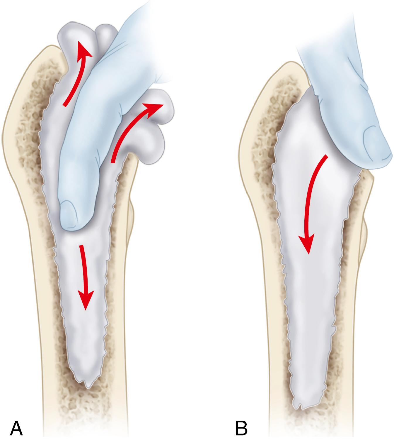
After the cavity has been filled, press the cement with the thumb ( Fig. 3.60B ). A mechanical impactor or plunger can be used. Two packages usually suffice, but additional cement may be necessary for larger medullary canals. A small plastic suction tube can be placed in the femoral canal to allow air and blood to escape while the cement is being inserted. If a suction tube is used, place it into the canal before the cement is introduced; remove it after about two thirds of the cement has been inserted.
After reduction of the hip, proceed with repair of the posterior soft-tissue envelope. Repair the preserved portion of the posterior capsule with heavy nonabsorbable sutures placed through holes in the posterior edge of the greater trochanter. Reattach the previously tagged tendons of the short external rotator muscles.
Repair any portion of the gluteus maximus insertion and quadratus femoris that has been divided.
Careful reconstruction of the posterior soft-tissue envelope greatly reduces the risk of postoperative dislocation.
If desired, place a closed-suction drain deep to the fascia. Abduct the hip 10 degrees while closing the fascial incision with closely approximated sutures. Tight closure of this layer helps stabilize the hip and may prevent a superficial inflammatory process from extending to a deeper level. Loosely approximate the subcutaneous layer with interrupted, absorbable sutures.
Close the skin in routine fashion.
The direct anterior approach uses the distal half of the traditional Smith-Petersen approach to the hip. Initially described by Light and Keggi in 1980, modifications of the approach have become considerably more popular over the last decade. The interval is both intermuscular and internervous, so little muscular dissection is required. Performed with the patient supine, the procedure can be done on a conventional radiolucent table or a specialized table similar to those used in fracture surgery. An accessory hook mounted on the side of the table can be used to aid in elevating the femur for preparation and component implantation. Intraoperative fluoroscopy can also be used to check the progress of reaming, the positioning of implants, and restoration of limb length. The position of the pelvis is also more reliable when the patient is supine than in the lateral decubitus position.
The approach traverses anatomy that may be unfamiliar even to experienced hip surgeons. The learning curve for the procedure can be improved by cadaver laboratory instruction sponsored by orthopaedic societies and industry or by personal visitation with surgeons already experienced in the procedure. Acetabular preparation and component implantation generally are straightforward. Access to the femur is more difficult, leading many surgeons to use shorter or curved femoral components to simplify the procedure (see Figs. 3.21C and 3.28 ).
Certain patient factors make the approach more complex. The interval cannot be safely extended distally, so a separate exposure is required to access the femur in patients with deformity requiring osteotomy, removal of previously placed implants, or placement of femoral cerclage. Access to the femoral canal can be more difficult in patients with a wide iliac crest and those with a short, varus femoral neck. In obese patients the subcutaneous layer about the anterior aspect of the hip tends to be thinner than the lateral aspect, and with the patient supine gravity displaces the tissues away from the incision. In patients with a large panniculus, however, the inguinal crease is prone to dermatitis and chronic fungal infection leading to problems with wound healing.
The anterior approach also has been advocated because of a low incidence of dislocation, although this difference has diminished with the use of larger femoral heads and soft-tissue repair. Some investigators have also reported faster functional recovery with the direct anterior approach, including shorter hospitalization, less narcotic use, and less reliance on ambulatory aids at 2 weeks. Few report any differences past 6 weeks postoperatively.
Position the patient supine on a radiolucent table with the ASIS at the level of the table break such that the operated limb can be positioned in marked hyperextension ( Fig. 3.61 ). Place a small bolster under the operative hip to aid in elevating the femur. If fluoroscopy is to be used, ensure that the pelvis is level and that both hips can be adequately imaged.
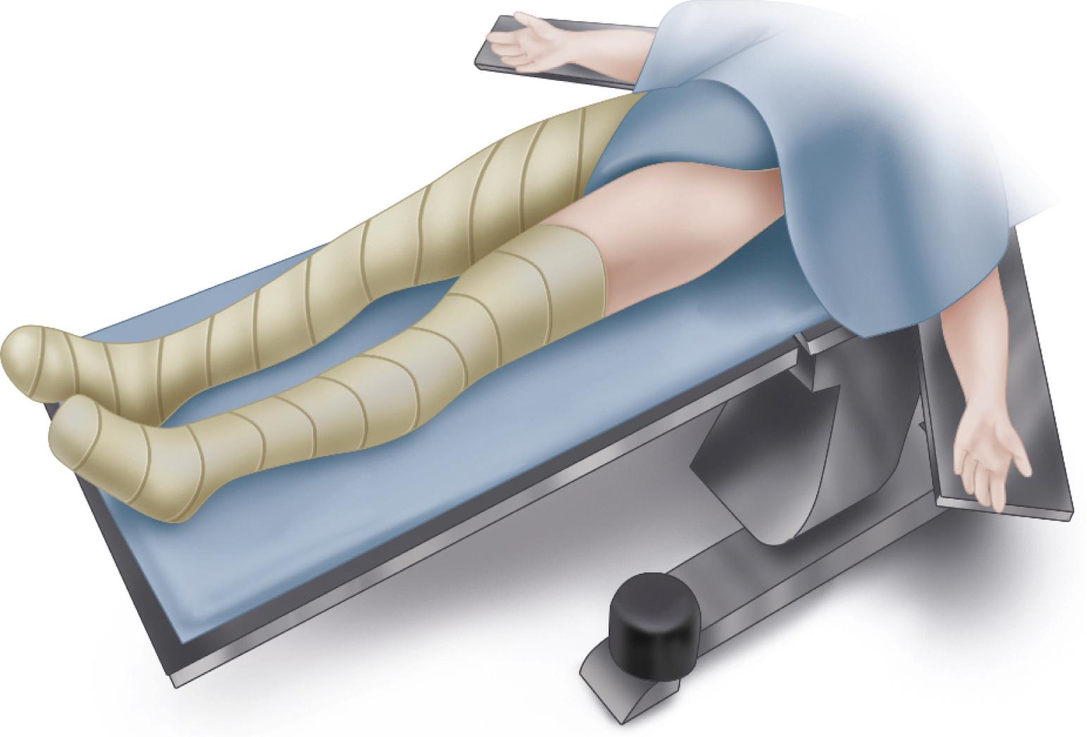
Prepare the skin of both lower limbs above the level of the ASIS and drape the limbs separately such that the operated limb can be crossed beneath the opposite limb in a figure-of-four position. An additional padded and draped Mayo stand is useful for supporting the opposite limb during preparation of the femur.
Place the skin incision lateral to the interval between the tensor fascia lata (TFL) and sartorius to avoid injury to the fibers of the lateral femoral cutaneous nerve (LFCN), which may be variable in its course. Begin the incision approximately 3 cm distal and 3 cm lateral to the ASIS. Extend the incision distal and slightly lateral for 8 to 12 cm.
Divide the fascia over the muscle belly of the TFL fibers to stay lateral to the LFCN ( Fig. 3.62A ).
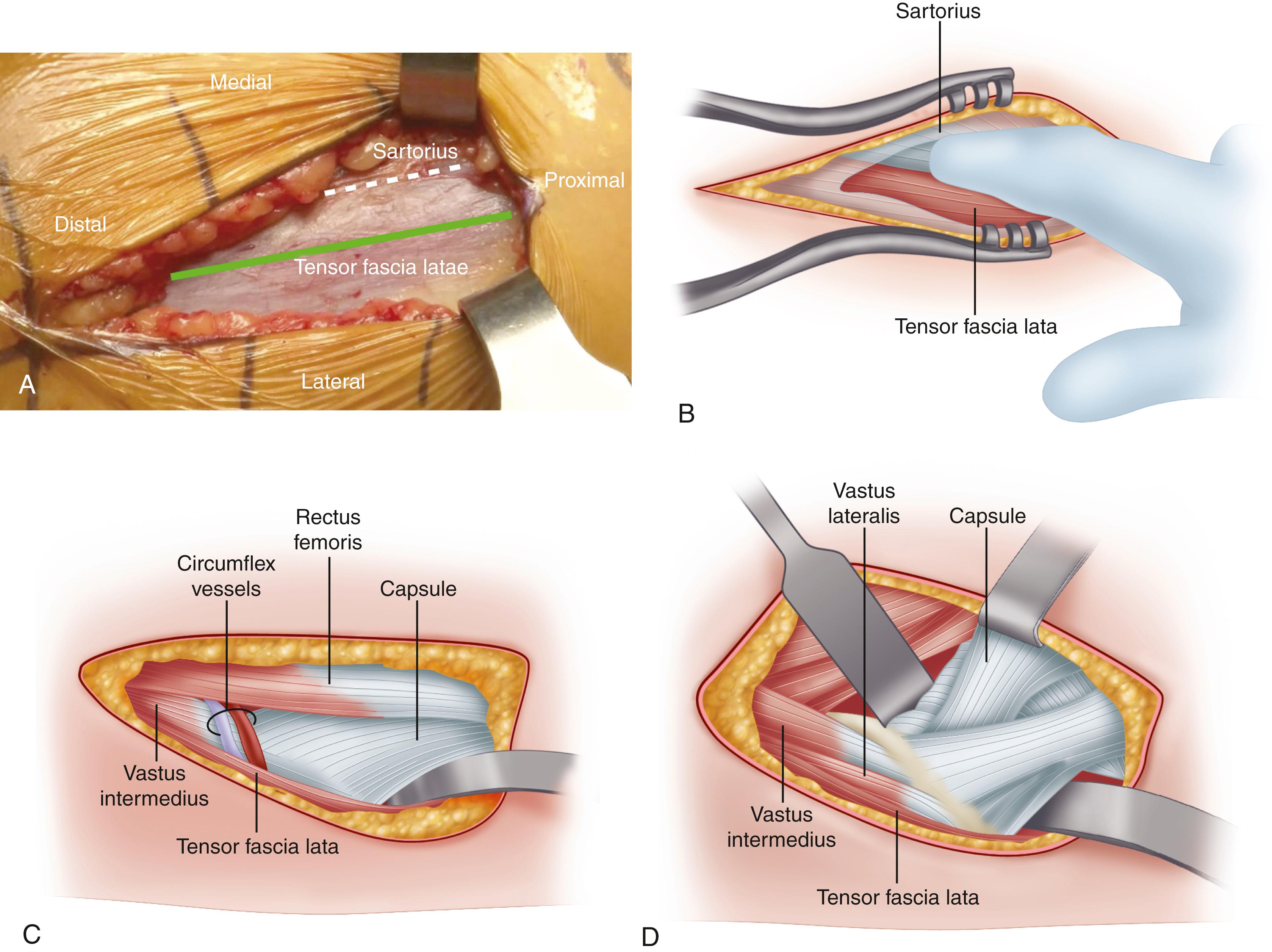
Now bluntly dissect medially with an index finger in the interval between the TFL and sartorius ( Fig. 3.62B ). If uncertain of the correct plane, expose proximally to ascertain that the dissected interval is lateral to the ASIS.
The femoral neck can be palpated through a thin layer of fat overlying the anterior capsule. Within this fat layer in the distal extent of the interval, locate the ascending branches of the lateral circumflex vessels and cauterize them with electrocautery or a bipolar sealer ( Fig. 3.62C ). Brisk bleeding may be encountered if these vessels are divided and allowed to retract.
Place blunt curved retractors superior and inferior to the femoral neck. Elevate the fibers of the rectus femoris from the anterior hip capsule and place a pointed retractor over the anterior rim of the acetabulum just distal to the direct head of the rectus ( Fig. 3.62D ). Release the fibers of the reflected head of the rectus to allow improved medial retraction of the direct head. Slight flexion of the hip also relaxes the rectus. Take care in the placement of the retractor beneath the rectus to avoid injury to the femoral nerve and vessels.
Divide the anterior hip capsule in a T-shaped or H-shaped fashion for later repair, or alternatively excise the capsule. Release the inferior capsule to the level of the lesser trochanter. Now replace the superior and inferior curved retractors inside the capsule to completely expose the femoral neck.
Perform an in situ osteotomy of the femoral neck at the level determined by preoperative templating. Measure the osteotomy from the lesser trochanter or by use of fluoroscopy. It may be necessary to make a second parallel osteotomy at the subcapital region producing a “napkin ring” of bone, which is secured with a threaded Steinmann pin for removal ( Fig. 3.63A ).
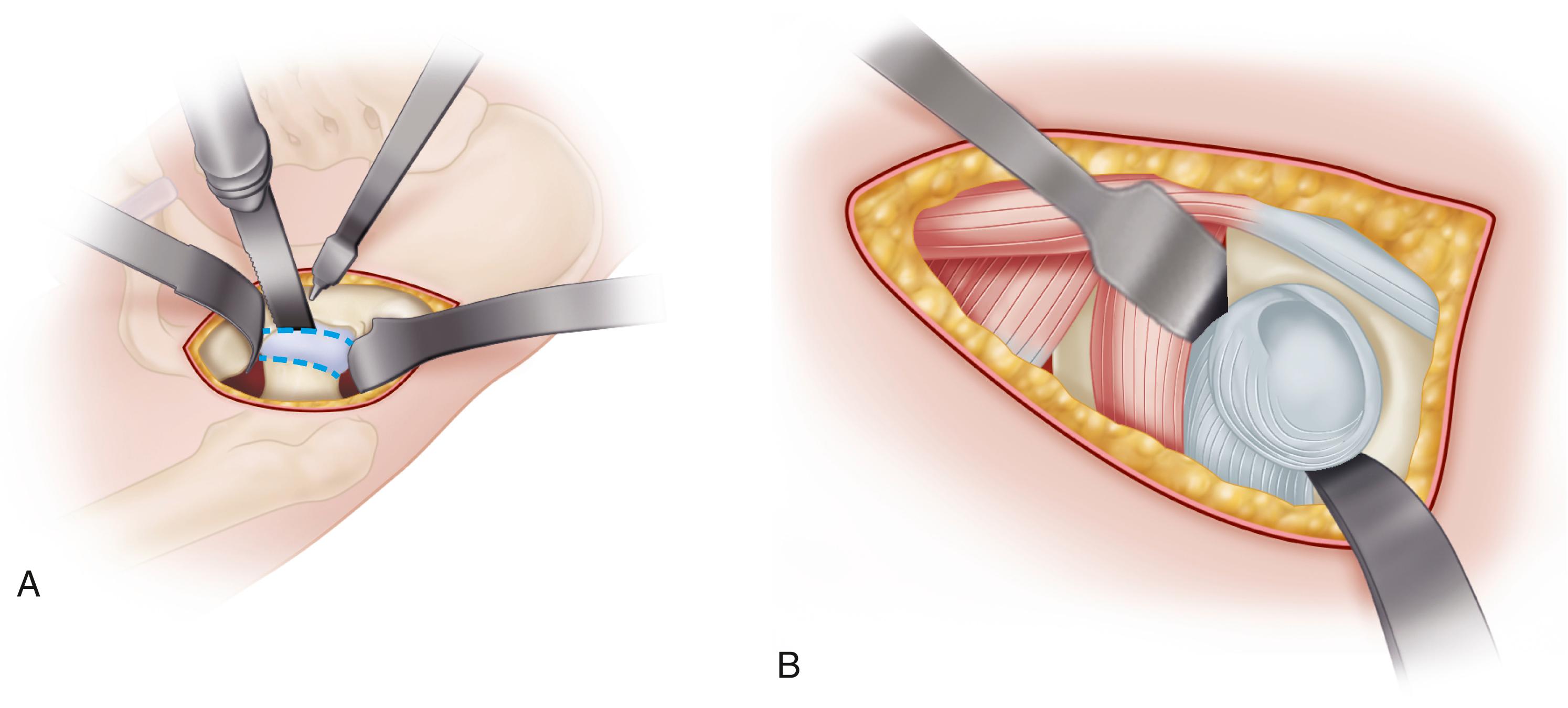
Extract the femoral head with a corkscrew, which can be placed before the neck osteotomy is made. Take care to protect the TFL from sharp bone edges when removing the femoral head. Recheck the neck osteotomy height. If the femoral neck is left excessively long, acetabular exposure will be more difficult.
To expose the acetabulum, place curved retractors distal to the transverse acetabular ligament and along the posterior rim of the acetabulum to displace the femur posteriorly ( Fig. 3.63 ). An additional retractor can be placed over the anterior acetabular rim if needed. Excise the labrum and prepare the acetabulum with reamers (see Fig. 3.45 ). Specialized offset reamers and cup positioners are available for this purpose. The progress of acetabular reaming and cup positioning can be verified using fluoroscopy. There is a tendency to place the cup in excessive abduction and anteversion with the patient supine.
Elevation of the femur is the most difficult step with the patient supine. To expose the proximal femur, place the operated limb in figure-of-four position beneath the opposite limb. Adduct the femur slightly and externally rotate 90 degrees. Avoid excessive knee flexion because this position tightens the rectus femoris, making femoral elevation more difficult.
Now “break” the table to position the operated hip in hyperextension. Raise the table and place it in the Trendelenburg position to prevent the lower end from approaching the floor. Support the opposite leg on a padded sterile Mayo stand or arm board ( Fig. 3.64A ).
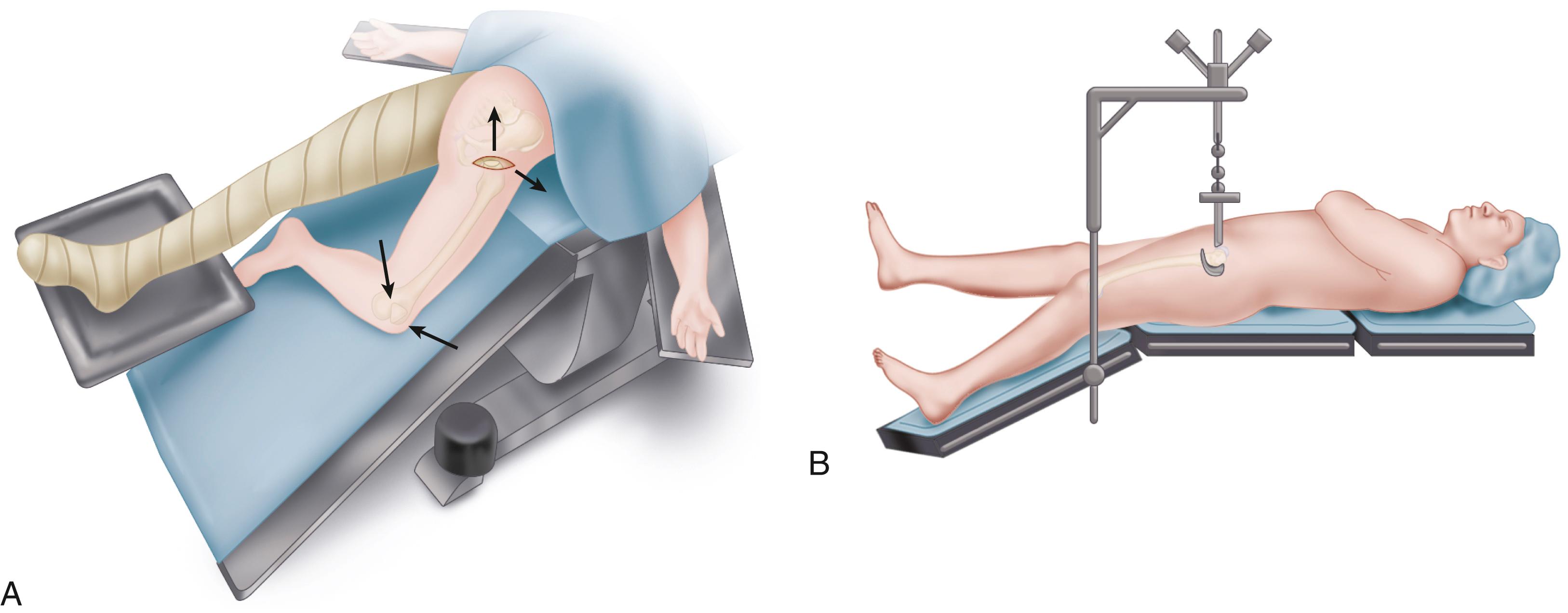
Elevate the femur laterally and upward with a bone hook placed within the femoral canal or around the lateral aspect of the femur. Take care that the femur is not trapped behind the acetabulum during this maneuver; elevation of the femur will be more difficult, or fracture of the greater trochanter may occur. A sterile hook mounted on a table attachment can be used during this step ( Fig. 3.64B ). Place the hook just distal to the vastus ridge. Position a curved retractor beneath the posteromedial femoral neck to retract the medial soft tissues. Place an additional pronged retractor over the tip of the greater trochanter to protect the abductor musculature and lift the femur anteriorly.
Additional soft-tissue release often is required at this stage to avoid excess retraction force, which may result in femoral fracture. Patients with fixed external rotation deformity typically require a greater amount of release to deliver the femur anteriorly. First, release the superior capsule from the greater trochanter from anterior to posterior, completely exposing the trochanteric fossa or “saddle” ( Fig. 3.65 ). In more difficult cases, release the piriformis and conjoined tendons to allow elevation of the femur without undue traction ( Fig. 3.66 ).
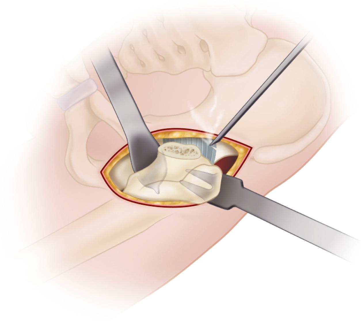
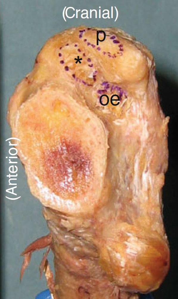
Prepare the femur and implant the femoral component (see Technique 3.5). It is technically easier to implant a femoral component using a broach-only technique because it may be difficult to pass straight reamers down the femoral canal even with satisfactory femoral exposure. Specialized angled broach handles and stem insertion devices also simplify the procedure ( Fig. 3.67 ). A canal sound or guide pin is useful to judge the alignment of the femoral canal and avoid varus stem positioning or perforation of the lateral femoral cortex.
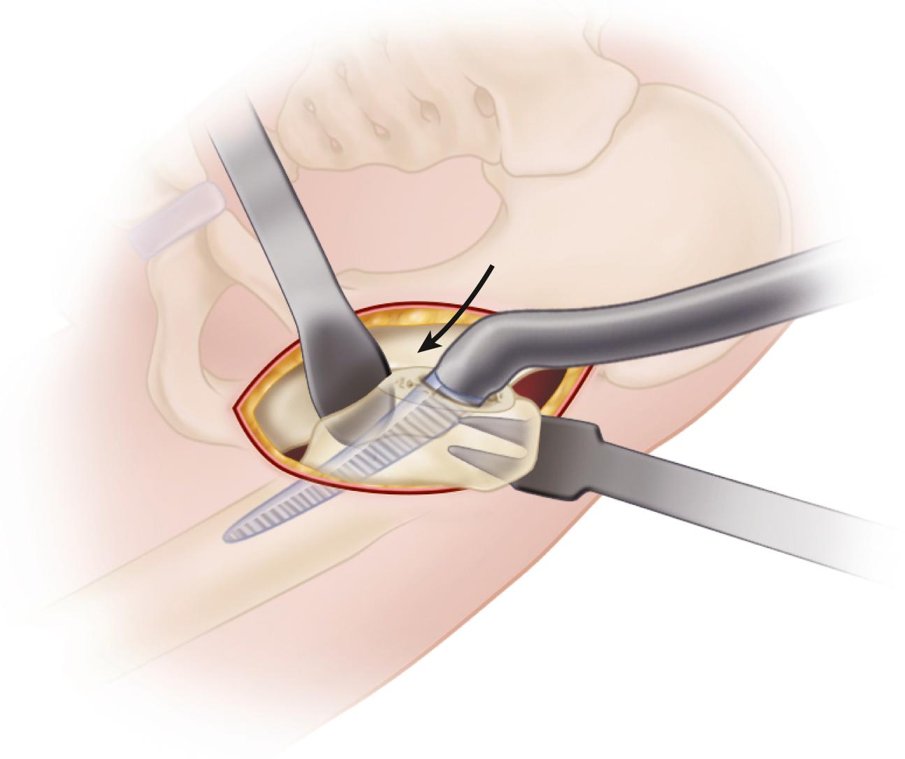
During the trial reduction of implants, take special care to assess the stability of the hip in extension and external rotation, particularly if a complete anterior capsulectomy has been performed during the initial exposure. Use fluoroscopy to assess position of the implants and restoration of limb length and offset. Limb length also can be assessed directly by comparison with the opposite limb.
If the anterior capsule has been retained, perform a secure closure of the capsular flaps. When closing the fascial layer, take small bites on the medial edge to avoid entrapment of the LFCN in the repair.
Some proponents of the supine intermuscular approach have advocated the use of a dedicated surgical table similar to those used in lower extremity fracture care. Both feet are secured in compression boots attached to mobile spars that allow traction, rotation, and angulation of the limb in any direction ( Fig. 3.68 ). An integral hook is used to aid in femoral elevation, and intraoperative fluoroscopic imaging is easily obtained. Because both feet are secured in boots, however, it is more difficult to manually assess the stability of the hip and directly compare limb lengths. The use of such a table requires a significant institutional financial investment, and the use of strong traction and limb rotation also introduces a risk of traction nerve palsy and fractures.
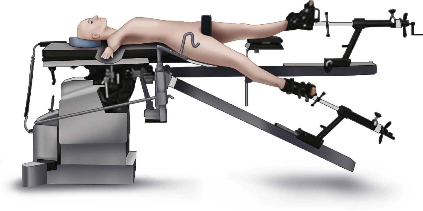
Matta et al. reported a series of 494 primary arthroplasties performed on a dedicated table. Clinical and radiographic results were excellent, but there was one femoral nerve palsy, three greater trochanteric fractures, two femoral shaft fractures, and three ankle fractures. The complications underscore the importance of obtaining exposure by judicious soft-tissue releases rather than by forceful traction and limb rotation.
The results using intraoperative fluoroscopy have been mixed. Hamilton et al. reported no excessively abducted cups (over 55 degrees) using fluoroscopy with the direct anterior approach. Leucht et al. found that fluoroscopy reduced the incidence of limb length discrepancy of more than 1 cm but did not improve the precision of cup positioning. In a large series from the Rothman Institute, Tischler et al. found no difference in acetabular inclination angle, leg length, or offset using fluoroscopy and concluded that the increased operative time and cost were not justified at a high-volume arthroplasty institution. Careful attention must be paid to both the tilt and rotation of the pelvis in relation to the x-ray beam to maximize the utility of intraoperative fluoroscopy. Standard protection in the form of a lead apron and thyroid shield are recommended for those in proximity to the beam. McArthur et al. reported radiation dose and fluoroscopy times that were comparable to other fluoroscopically guided hip procedures.
Hip arthroplasty has been performed through small incisions by Kennon et al. since the 1980s. More recently, minimally invasive techniques have been introduced to the orthopaedic community and have received widespread media attention. The term minimally invasive total hip replacement does not describe a single operation but rather a group of procedures performed through various incisions of smaller dimensions than traditionally described.
The introduction of these techniques has generated considerable controversy in the orthopaedic community. Advocates of these techniques have advanced the position that minimally invasive hip replacement has the potential to reduce soft-tissue injury, postoperative pain, operative blood loss, and hospital length of stay; increase speed of the patient’s postoperative rehabilitation; and produce a more cosmetically acceptable surgical scar. Adoption of minimally invasive techniques has revolutionized other procedures, such as meniscectomy, cruciate ligament reconstruction, rotator cuff repair, discectomy, and others. Critics of these new techniques cite the excellent results of current methods with regard to pain relief, functional improvement, and long-term durability, with a remarkably low complication rate. The potential benefits of smaller incisions must be weighed against the pitfalls of poor exposure and the learning curve associated with any new procedure. There is the potential for implant loosening from suboptimal bone preparation, dislocation from malpositioned implants, infection and delayed wound healing from trauma to the skin, unrecognized fractures, neurovascular compromise, and leg-length inequality from the lack of exposure of bony landmarks. All of these problems may require reoperation and are likely to be more common in the hands of surgeons performing fewer procedures. Surgeons must decide whether the potential risks in adopting minimally invasive techniques are justifiable given the scope of their individual practices.
There is general consensus that a minimally invasive hip arthroplasty is done through an incision of 10 cm or less. A single posterior incision is currently the most commonly used approach, followed by single-incision direct anterior approaches. We have gradually adopted minimally invasive techniques and now perform hip arthroplasty in most patients through a single posterior incision of 8 to 10 cm ( ). We have more recently adopted the direct anterior approach in selected primary procedures.
Thin patients are ideal for minimally invasive approaches. The operation is more difficult in muscular males and obese patients (BMI > 30 kg/m 2 ). Although a longer incision may be needed in these individuals, the same principles can be applied. Patients requiring revision surgery and patients with dysplasia, prior reconstructive procedures, or very stiff hips require larger incisions. As a basic tenet, there should never be any hesitation to lengthen the incision if exposure is inadequate. An operation done well through a larger incision is preferable to an unsatisfactory result with a small incision.
At a given time, only a portion of the hip is exposed. A variety of specialized instruments are helpful in gaining exposure and viewing the acetabulum and femur while protecting the surrounding soft tissues ( Fig. 3.69 ). A long Charnley retractor blade is needed to avoid excessive stretching of the wound corners. Acetabular retractors with long handles and blades narrower than usual reduce clutter within the wound. Some systems have incorporated fiberoptic lighting into acetabular retractors. Angulated acetabular reamer shafts and component positioning devices reduce the retraction required on the inferior soft tissues. Reamers with side cutouts are more easily inserted into the acetabulum and appear to be acceptably accurate. It is particularly helpful to have an assistant to position the limb for femoral preparation and implant placement. Exposure also is enhanced by the use of hypotensive regional anesthesia to reduce intraoperative bleeding.
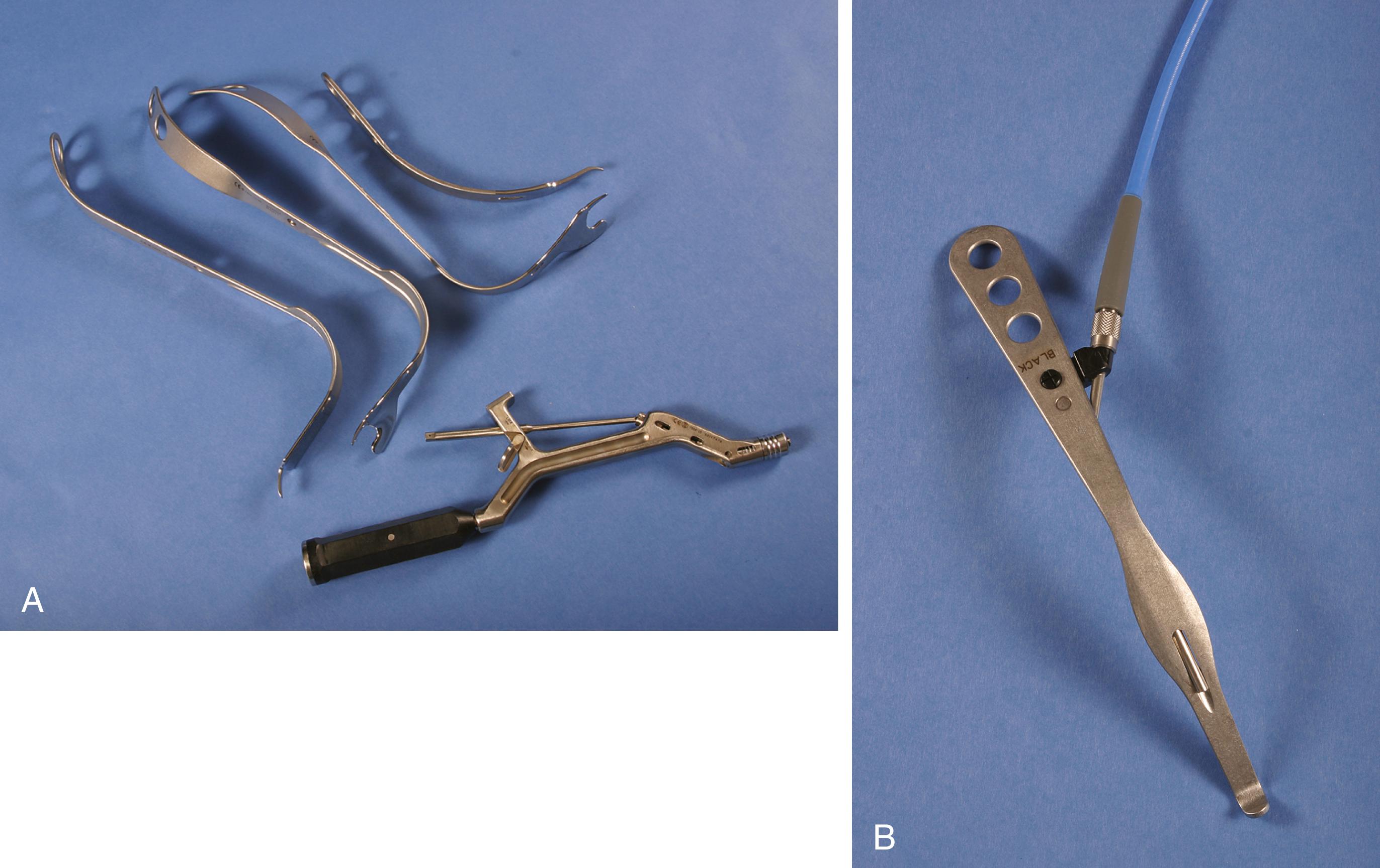
Sculco and Jordan advocated a posterolateral approach to the hip through a 6- to 10-cm incision. The incision is placed in line with the femur along the posterior edge of the greater trochanter with approximately one third of the incision proximal to the tip of the greater trochanter and two thirds distal. The gluteus maximus is split for only a short distance, the incision of the fascia lata is limited, and the quadratus femoris is left mostly intact but retracted to expose the lesser trochanter and resect the femoral neck. The incision may be easily extended in either direction to approximate a more traditional posterior approach if needed. In a prospective randomized study by this group, Chimento et al. showed that patients with an 8-cm posterolateral approach had less intraoperative and total blood loss and limped less at 6 weeks’ follow-up than patients with a standard approach. There were no differences in operative time, transfusion requirements, narcotic use, hospital stay, or other rehabilitation milestones. Complications were similar in the two groups, and a 5-year follow-up on the same cohort showed no radiographic loosening. Radiographic measures of cup and stem position and cement technique were not compromised in the minimally invasive group. DiGioia et al. found that patients in the mini-incision group walked with less of a limp and had better stair-climbing ability at 3 months and improvement in the limp, distance walking, and stair-climbing at 6 months. There were no differences at 1 year. In a prospective, randomized series, Dorr et al. found that a group that had minimally invasive surgery had shorter hospital stays, less in-hospital pain, and less need for assistive devices. There were no differences after hospital discharge.
Other investigators have not shown any benefit to the use of a smaller incision. In a prospective, randomized, controlled trial, Ogonda et al. found that a minimally invasive approach was safe and reproducible but offered no benefit compared with a traditional approach. The trial was done after the senior author had gained considerable experience with less invasive techniques, and the learning curve was not included in this series. In another study from the same institution, Bennett et al. found no difference in any gait analysis parameter at 2 days after surgery. Goldstein et al. likewise were unable to show any differences between a standard and minimally invasive posterolateral approach. In another prospective series with 5-year follow-up, Wright et al. found no difference other than patients’ enthusiasm regarding the cosmetic appearance of the scar.
Minimally invasive anterior incisions are modifications of the Smith-Petersen approach. Although the acetabular exposure is superior, it can be difficult to place the femur in a position where the stem can be inserted in line with the shaft. Several manufacturers have introduced shorter stems with curved broaches to simplify femoral component placement (see Fig. 3.28 ). Although a claim of the anterior approach is that no muscle or tendon is transected, multiple authors recommend release of the posterior capsule and short external rotators to deliver the femur into the wound. Problems related to injury to the lateral femoral cutaneous nerve (LFCN) have led many to place the skin incision slightly lateral to the intermuscular plane of the deeper dissection.
Parratte and Pagnano evaluated tissue injury with various approaches and concluded that it is not possible to routinely perform minimally invasive THA without causing some measurable degree of muscle damage. Rather, the location and extent of muscle damage is specific to the approach. Tissue damage in the anterior approach involved the anterior part of the gluteus medius, the TFL, and the external rotators. The posterior approach was associated with substantial damage to the short external rotators and gluteus minimus and a small amount of damage to the gluteus medius. Bergin et al. measured serum inflammatory markers in patients undergoing hip arthroplasty through minimally invasive posterior and anterior approaches. Serum creatine kinase levels in the posterior group were 5.5 times higher than the anterior group in the postanesthesia unit. The clinical significance of the finding was not delineated.
Advocates frequently describe enhanced recovery after minimally invasive hip arthroplasty. However, multimodal pain management and accelerated rehabilitation protocols have been introduced simultaneously, and these factors also influence the speed of recovery. In a series of 100 patients, Pour et al. found that at the time of hospital discharge, patient satisfaction and walking ability were better in patients who had received an accelerated preoperative and postoperative rehabilitation regimen regardless of the size of the incision. Poehling-Monaghan et al. found no systematic advantage of a direct anterior approach over a mini-posterior approach when using the same rapid rehabilitation protocols with no hip positioning precautions.
Minimally invasive techniques and instrumentation continue to evolve. Refinements in surgical approaches and the integration of computer-assisted navigation may ultimately improve outcomes and surpass the excellent results of standard hip arthroplasty procedures. Rigorous scientific study of these new methods must precede widespread adoption in clinical practice.
Improper positioning of acetabular and femoral components may compromise the outcome of the arthroplasty because of impingement, dislocation, increased wear, and leg-length discrepancy. Patient size, the presence of deformity, limited surgical exposure, intraoperative movement of the pelvis, inaccuracies in conventional instrumentation, and surgeon experience are all variables that may negatively affect the accuracy of component positioning. Surgeons’ assessments of intraoperative position of both femoral and acetabular components are inaccurate when compared with postoperative CT scans. Strategies such as computer-assisted surgical navigation are being investigated to improve the accuracy of the operation.
Computer-assisted navigation provides the surgeon with real-time information regarding the positioning of the femur and pelvis relative to each other and to the surgical instrumentation. The tracking of these positions is by infrared stereoscopic optical arrays that must be visible to a camera. Navigation of the acetabular component requires registration of anatomic landmarks to allow the computer to determine the position of the pelvis in space. Although individual navigation systems vary in both durable equipment and software algorithms, there are three general types of systems: imageless, fluoroscopic, and CT based.
Imageless navigation is based only on landmarks that are digitized at the time of surgery without confirmation by imaging studies. A reference frame is attached to the pelvis, and an optical pointer is then used to reference the ASIS and pubic symphysis by palpation or by small percutaneous incisions. The registration process is performed with the patient supine to allow access to the opposite anterior spine. If the operation is to be done with the patient in the lateral position, the optical tracker is mounted to the pelvis and must be prepared and draped into the surgical field after the patient is repositioned. In larger patients, inaccurate digitization of pelvic landmarks can introduce errors. Computer screen images are of standardized bone models and do not reflect the patient’s individual anatomy. Using imageless navigation, Hohmann et al. demonstrated a significant decrease in deviation of acetabular component placement with respect to both inclination and anteversion compared with conventional techniques. Ellapparadja et al. found restoration of both leg length and offset within 6 mm in over 95% of cases. Conversely, Brown et al. found no difference in acetabular inclination angle or leg-length discrepancy between imageless navigation and conventional techniques.
When fluoroscopic navigation is used, reference frames are again applied to the bones. Fluoroscopic images made at multiple angles are combined to yield three-dimensional information. The referencing process can be performed with the patient in the lateral position. If there is a change during the procedure, then new images may be acquired. A radiolucent operating table is required, and protective lead aprons must be worn by the surgical team. Bulky fluoroscopic equipment must remain available during the procedure, and time has to be allotted for acquisition of images. Fluoroscopic navigation has been more reliable for limiting variability of cup abduction than for anteversion. No preoperative planning or imaging is required. Consequently, the technique provides no information about the requirements for restoration of proper hip mechanics.
CT-based navigation provides detailed, patient-specific information compared with imageless and fluoroscopic techniques. Information from the preoperative CT scan is used to produce a virtual bone model which is then coupled to the patient’s bony anatomy by the process of registration. Intraoperative registration requires digitization of multiple points on the bony surface of the acetabulum using an instrumented pointer that are then mapped onto the computer model. The process can be done with the patient in the lateral position without the need for repositioning. The accuracy of the mapping and navigation can be confirmed in real time. Detailed information is available preoperatively regarding component size, positioning, leg length, offset, and range of motion. Preoperative imaging and planning are required, but no intraoperative imaging is needed, and the surgical procedure is consequently faster than with imageless navigation.
Beckmann et al., in a meta-analysis of the use of navigation to improve acetabular component position, found that whereas mean cup inclination and anteversion angles were not significantly different, navigation reduced the variability in cup position and the risk of placing the acetabular component beyond the safe zone. Long-term outcomes and cost utility data were not available. Moskal and Capps drew similar conclusions and found fewer dislocations in hips with navigated acetabular component placement. To assess the accuracy of navigation in correcting leg length, Manzotti et al. compared 48 navigated hip arthroplasties with a matched cohort of procedures using a traditional freehand alignment method. Restoration of limb length was significantly better in the computer-assisted group. Dorr et al. reported using navigation to optimize restoration of offset: offset was restored within 6 mm of the contralateral hip in 78 of 82 hips.
Interest in robotic technologies has increased over the past decade, although to a lesser degree than in knee arthroplasty. Robotics complement surgical navigation with the addition of both bone preparation and component implantation being assisted by a sterile draped robotic arm. Current systems are CT based and require intraoperative placement of tracking arrays and bony registration. Typically, the femur is prepared first and femoral version assessed. Acetabular version can then be adjusted to obtain correct combined anteversion. Acetabular reaming is carried out with visual and tactile feedback from the computer, and bone removal outside of the planned resection is effectively prevented. The acetabular component is then implanted with precision guidance from the robotic arm according to the preoperative plan. Kanawade et al. found a contemporary robotic system achieved precision in acetabular inclination, anteversion, and center of rotation in over 80% of cases.
There has been little development of patient-specific instrumentation in THA compared with knee procedures. In one study, Small et al. found that such instruments improved accuracy of acetabular anteversion but not abduction angle.
Computer-assisted navigation appears effective in reducing outliers in component positioning and can be beneficial in restoring optimal hip mechanics. Whether these advances in accuracy will translate to improvements in outcomes and implant survivorship remains to be validated. The cost of necessary equipment, software, and imaging studies may be prohibitive for many institutions.
Although osteotomy of the trochanter for exposure and lateral reattachment to lengthen the lever arm of the abductors was an integral part of Charnley’s concept of THA, most total hip procedures are done now without osteotomy. The advocates of osteotomy believe that in addition to the opportunity to advance the trochanter laterally and distally at the time of surgery, dislocation of the hip is easier, exposure of the acetabulum is better, preparation of the femoral canal is complicated by fewer penetrations, cement can be inserted more optimally, and components can be inserted more easily and more accurately. The disadvantages of osteotomy are increased blood loss, a higher incidence of hematoma formation, longer operating time, technical difficulty with fixation of the trochanter, nonunion, wire breakage, bursitis, greater postoperative pain, and delayed rehabilitation.
In most patients, adequate exposure can be obtained with the posterolateral, anterior, anterolateral, or direct lateral approach without osteotomy of the trochanter. Although leaving the trochanter intact has many advantages, osteotomy may be necessary if the anatomy of the hip is markedly distorted, such as in cases of ankylosis or fusion, severe protrusio acetabuli, or developmental dysplasia with high dislocation of the hip. Occasionally, residual laxity of the abductor musculature results in hip instability despite proper restoration of length and offset. In this instance, trochanteric osteotomy with distal reattachment can render the hip more stable without lengthening the limb excessively. In revision procedures, trochanteric osteotomy facilitates exposure of the femur and acetabulum and may be required to extract the femoral component without excessive risk of fracturing the femur.
Three basic types of trochanteric osteotomies are currently used in hip arthroplasty: (1) the standard or conventional type, (2) the so-called trochanteric slide, and (3) the extended trochanteric osteotomy ( Fig. 3.70 ). Various modifications have been described for each type. The various types are suitable for specific purposes and should be tailored to the procedure being contemplated. Finally, the fixation method must be adapted to the type of osteotomy.
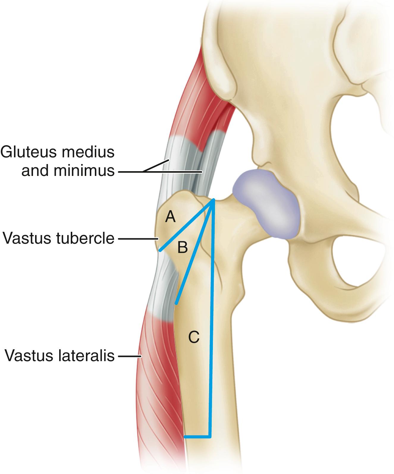
The standard trochanteric osteotomy is indicated when extensile exposure of the acetabulum is needed for complex revisions of the acetabular component, placement of an antiprotrusio cage, or a large structural bone graft. Superior retraction of the greater trochanter and abductor musculature yields unparalleled exposure of the ilium with less tension on the superior gluteal neurovascular bundle than would be experienced with the trochanteric slide technique. When a standard trochanteric osteotomy is done, the vastus lateralis first should be detached subperiosteally from the lateral aspect of the femur distal to the vastus tubercle. The osteotomy may be made with a power saw or an osteotome. The osteotomy is initiated just distal to the vastus tubercle and directed proximally and medially at an angle of approximately 45 degrees to the shaft of the femur. It should not extend into the femoral neck, and special care must be taken not to injure the sciatic nerve. In general, a large piece of bone should be removed, with all of the tendinous attachments of the gluteus medius and underlying gluteus minimus muscles. Other soft-tissue attachments, including the short external rotators, are released as necessary to allow superior retraction of the trochanteric fragment. The osteotomy also can be made with a Gigli saw passed deep to the abductor muscles and directed laterally ( Figs. 3.71 and 3.72 ). Charnley emphasized keeping the “strap” of the lateral capsule from the superior aspect of the acetabulum to the base of the trochanter intact to make reattachment more stable than pulling on muscle fibers alone.
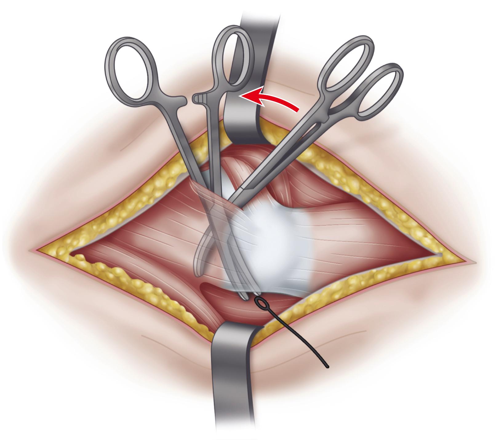
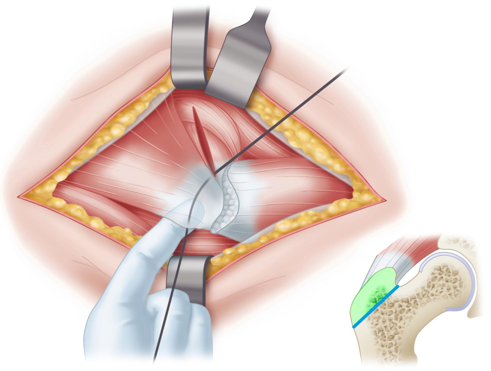
Excessive tension on the trochanter by the abductors can be lessened by maintaining the distal soft-tissue attachments on the trochanter. Glassman, Engh, and Bobyn described a technique of osteotomy that maintains an intact musculoosseous sleeve composed of the gluteus medius, greater trochanter, and vastus lateralis. This technique has been termed the trochanteric slide technique ( Fig. 3.73 ). Although nonunion rates for this procedure were similar to the rates for other techniques, superior migration of more than 1 cm occurred in only 11% of the nonunions, and the incidence of abductor insufficiency and limp was significantly lower than in similar series. Neither a standard osteotomy nor a trochanteric slide is ideal when the bed for reattachment has been compromised, such as when the greater trochanter has been filled with cement.
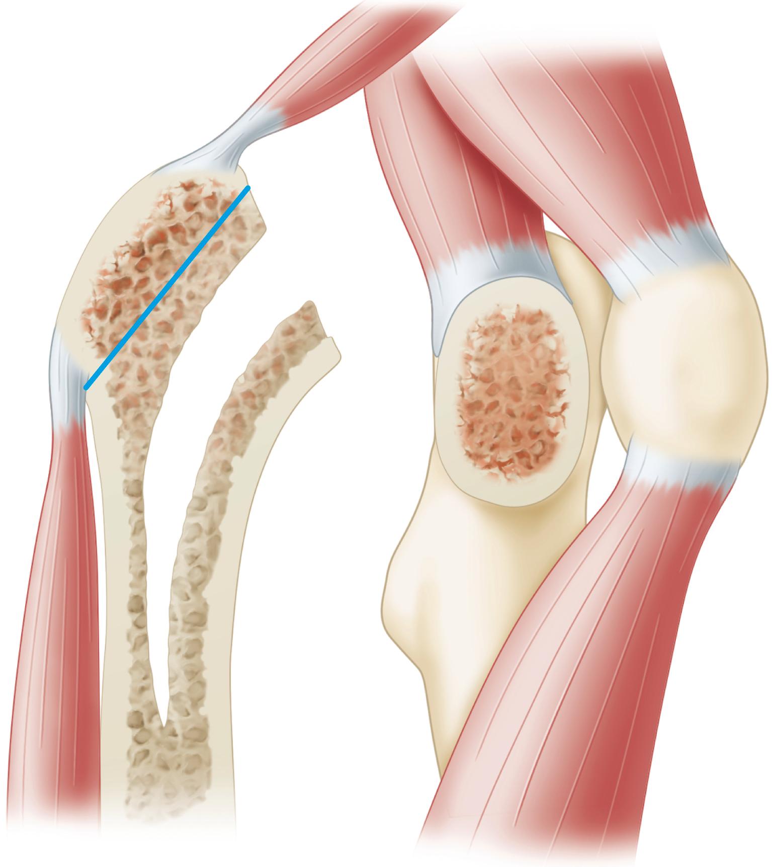
More recently, various techniques of extended trochanteric osteotomy have been introduced. In essence, these are proximal femoral osteotomies in which a segment of the lateral femoral cortex of variable length is raised in continuity with the greater trochanter. These techniques are of greatest benefit in removing well-fixed implants in revision surgery and when the bony bed for reattachment of a standard osteotomy would be compromised. Because a large segment of the lateral femoral cortex is removed, and cementing techniques are rendered imperfect, extended trochanteric osteotomies are used only when a cementless femoral reconstruction is anticipated (see Technique 3.5). Lakstein et al. described a modified technique in which the posterior capsule and short external rotators are left intact to reduce the risk of dislocation.
The lever arm of the abductors is lengthened according to the amount of lateral placement of the osteotomized trochanter. The hip should not be abducted more than 10 to 15 degrees while the trochanter is being reattached, or excess strain on the fixation would result when the hip is adducted, and avulsion and nonunion of the trochanter may follow. The position of reattachment of the greater trochanter has been found to affect the rate of union. Anatomic reduction or a slight distal overlap of the trochanter results in trochanteric union within 6 months. Fixation of the trochanter with residual superior and medial tilt invariably led to delayed union or nonunion. For union to occur reliably, compression must be applied across the osteotomy. Fixation should stabilize the trochanteric fragment to vertical and anterior displacement. Displacement in the anteroposterior plane occurs when the hip is loaded in flexion, and fixation failure is more complex than the abductors simply pulling the trochanteric fragment superiorly. A biplanar or chevron osteotomy yields greater resistance to anteroposterior displacement than a uniplanar osteotomy. Such an osteotomy is useful in complex primary procedures but is impractical in most revisions because of the loss of bone needed not only to perform but also to repair the osteotomy.
Various wire fixation techniques using two, three, or four wires have been described and are illustrated in Figures 3.74 and 3.75 . No. 16, 18, or 20 wire can be used, and because spool wire is more malleable, it is easier to tighten and tie or twist. A Kirschner wire spreader or wire tightener is used to tighten the wire. Stainless steel, cobalt-chrome alloy, or titanium alloy wire may be used, depending on the metal of the femoral component. Also, multiple filament wire or cable is available; the ends are pulled through a short metal sleeve, which is crimped after the wire has been tightened. Special care should be taken not to kink or nick the wire.
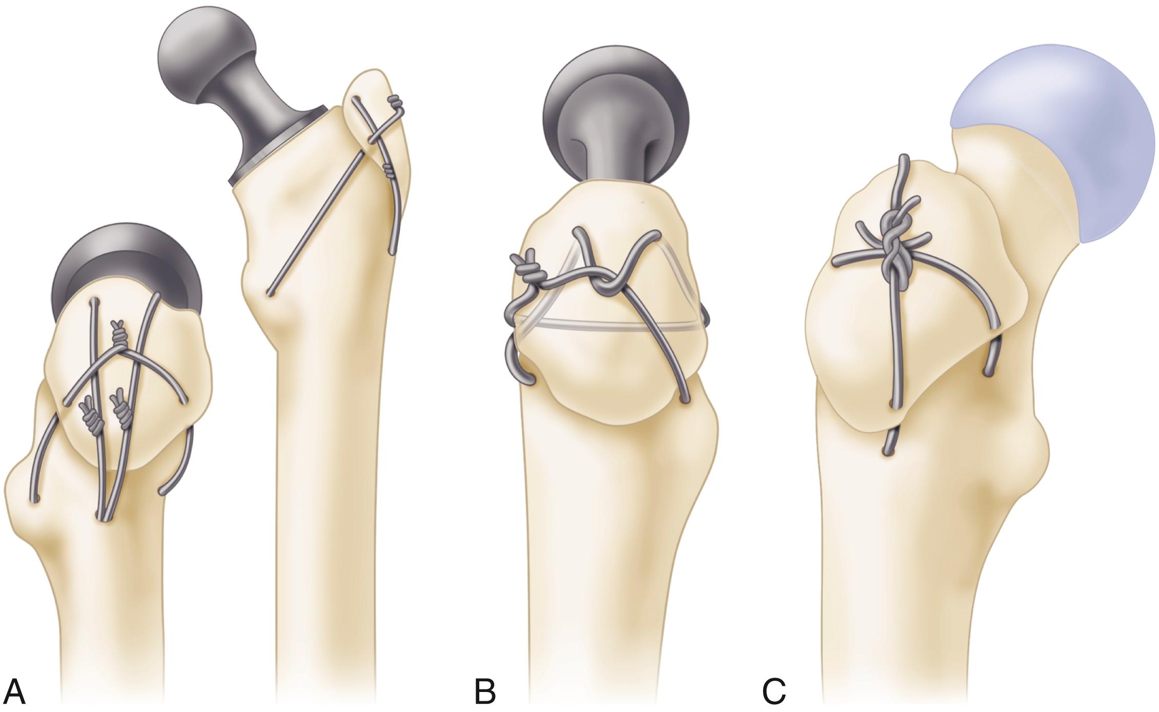
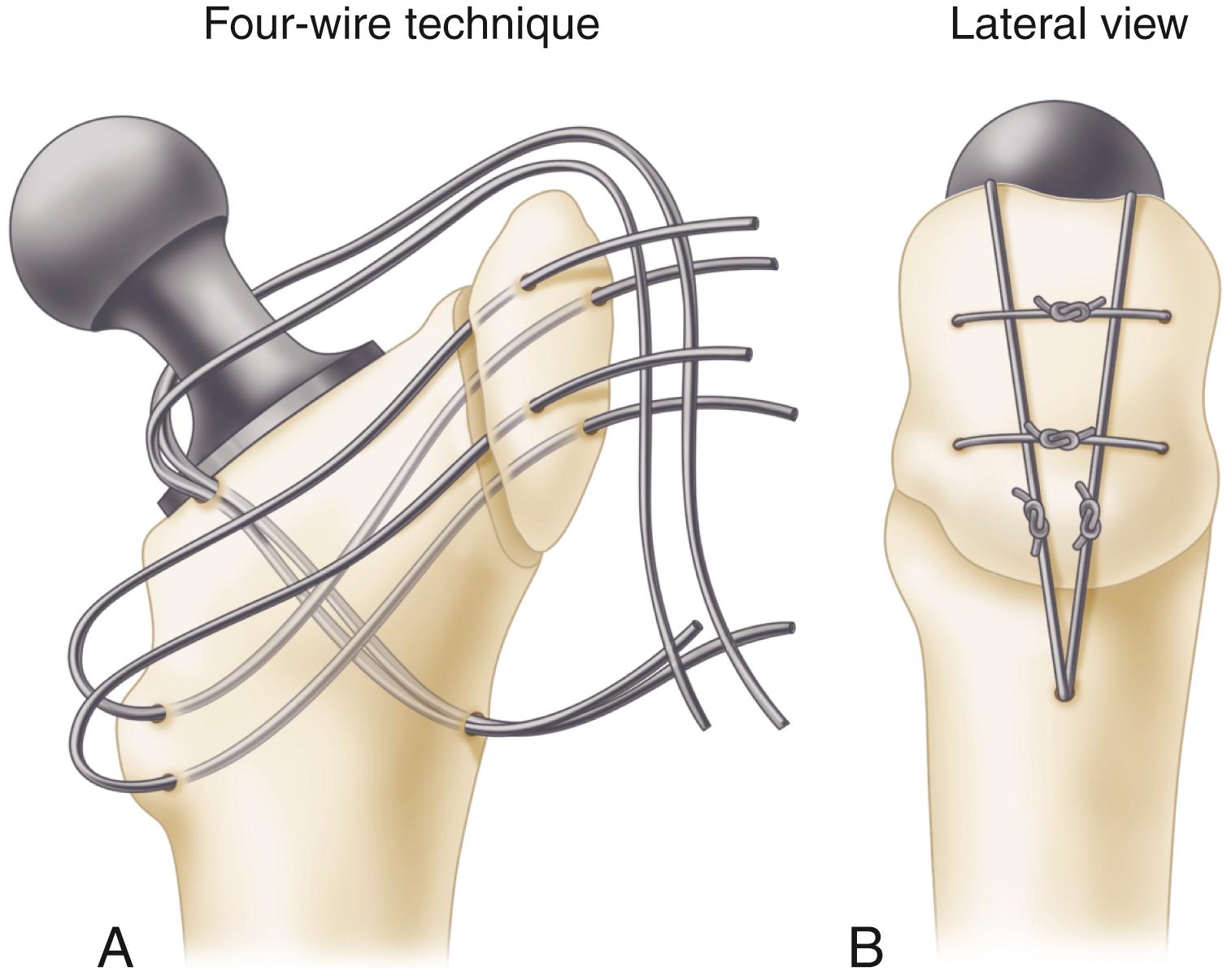
In our experience, wire fixation techniques do not predictably provide rigid fixation of the trochanter. Trochanteric nonunion rates of 25% have been reported using wiring techniques. With the trend toward cementless femoral revision, techniques requiring intramedullary passage of wires and screws have become difficult. In most cases, we prefer an extramedullary cable fixation device instead ( Figs. 3.76 and 3.77 ). A variety of new devices featuring proximal hooks with a plate extension also are available ( Fig. 3.78 ). Full weight bearing on the hip should be delayed for 4 to 6 weeks if fixation is not rigid. When fixation is less stable (i.e., with a small piece of bone or soft bone, difficulty in pulling the bone down to the femur, or loss of the bony bed for reattachment of the trochanteric fragment), the hip may be maintained in abduction in a spica cast or orthosis for 6 weeks. (See the section on complications for trochanteric nonunion and wire breakage problems.)
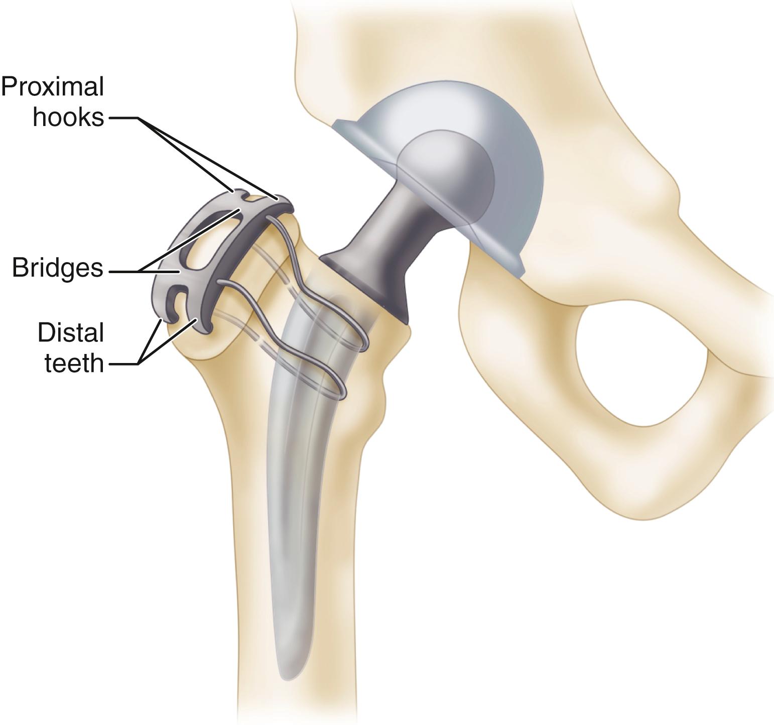
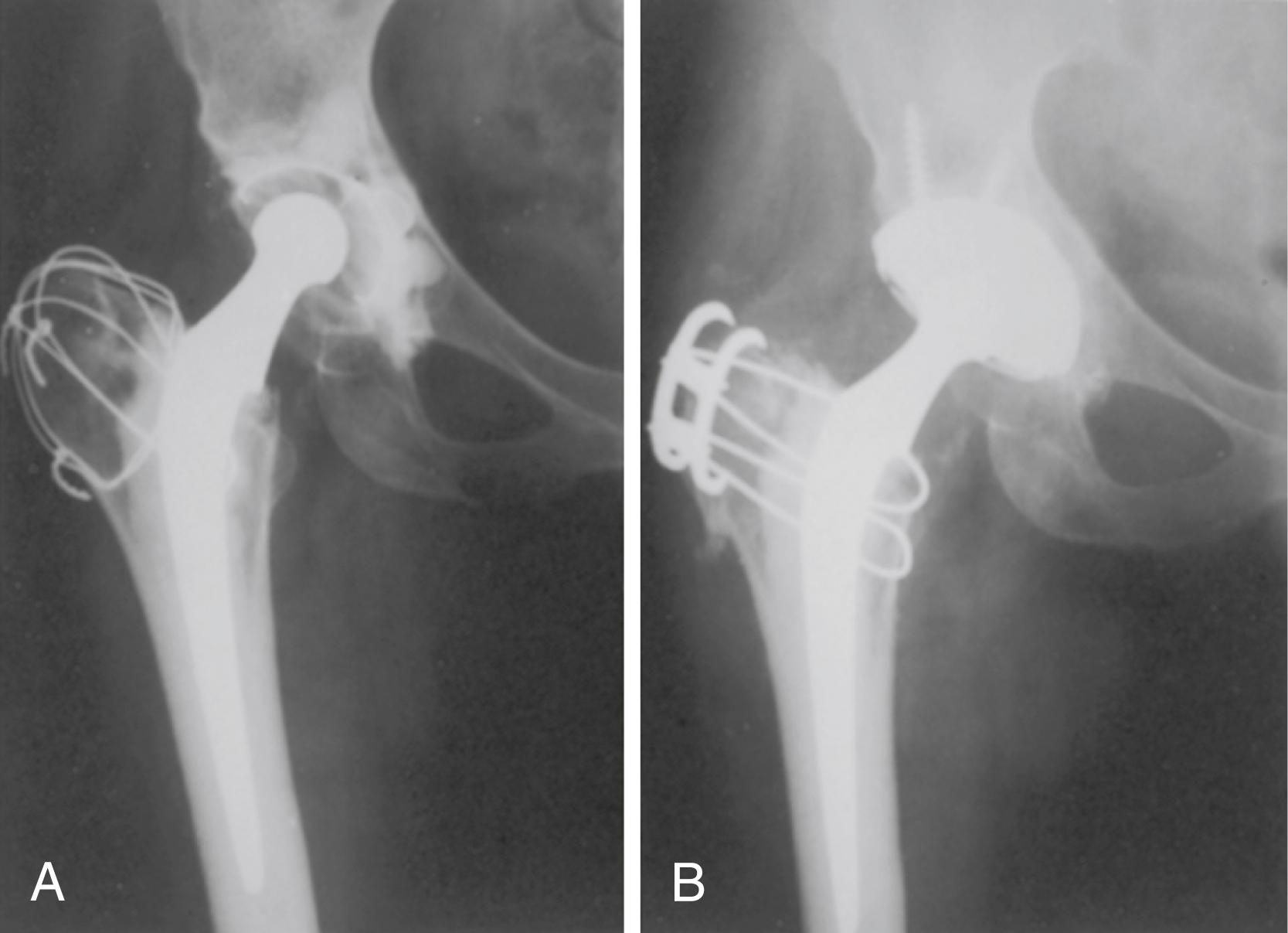
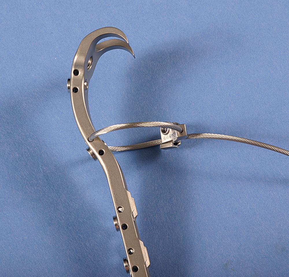
Dall described a modification of the direct lateral approach that involves osteotomy of the anterior portion of the greater trochanter rather than division of the anterior portion of the abductor insertion from the trochanter. Head et al. used a similar osteotomy in conjunction with an extensile direct lateral approach for revision arthroplasty ( Fig. 3.79 ). This approach detaches only the internal rotational component of the abductors and leaves the important abductor portion of the gluteus medius intact. Reattachment of the anterior trochanteric fragment allows for primary bony union and is easier than direct repair of the abductor tendon to bone.
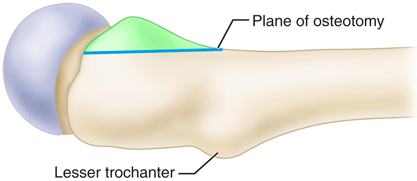
Much information has been accumulated since the 1970s concerning the various entities for which THA has been performed. In some instances, the routine surgical techniques must be modified to meet the needs of the various conditions. For this reason, the following entities are discussed relative to THA. Revision surgery for failed THA is discussed in a separate section.
Osteoarthritis is the most common indication for THA; it can be primary or secondary to femoroacetabular impingement, to previous trauma, or to childhood disorders of the hip. The extremity often is shortened slightly, although the discrepancy can be greater than 1 cm if erosion or deformation of the femoral head or acetabulum has occurred. The hip often is flexed, externally rotated, and adducted, and there is additional apparent shortening of the limb because of the deformity. Less commonly, the limb may appear lengthened because of a fixed abduction contracture. Removal of the osteophytes from the anterior or posterior margin of the acetabulum may be necessary to dislocate the hip safely. The subchondral bone of the acetabulum is thick and hard, and considerable reaming may be required before a bleeding surface satisfactory for bone ingrowth is reached. Osteophytes may completely cover the pulvinar and obscure the location of the medial wall.
If the femoral head has been displaced laterally, intraarticular osteophytes inferiorly may thicken the bone considerably and require deepening of the acetabulum to contain the cup fully ( Fig. 3.80 ). Failure to medialize the acetabulum in this instance may leave the superior portion of the cup unsupported or supported primarily by osteophytes rather than native bone. Careful attention to the removal of acetabular osteophytes is necessary to avoid impingement, decreased range of motion, and dislocation. Trochanteric osteotomy usually is unnecessary, but often the greater trochanter is enlarged, and some bone must be removed from its anterior or posterior surface to prevent impingement during rotation.
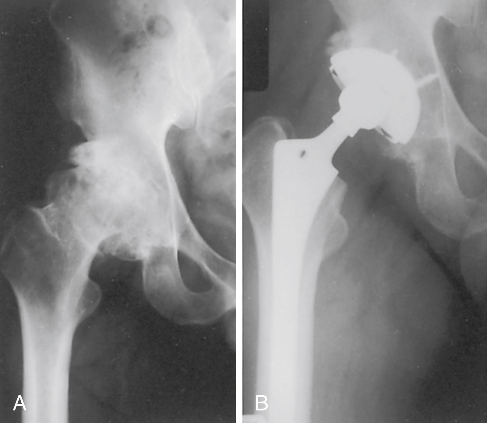
THA often is indicated to relieve pain and increase range of motion in patients with inflammatory arthritis and other collagen diseases, such as rheumatoid arthritis, juvenile idiopathic arthritis, juvenile rheumatoid arthritis or Still disease, psoriatic arthritis, and systemic lupus erythematosus, especially when involvement is bilateral. Arthroplasties of the knees and other joints may be necessary. Often these patients are generally disabled, having varying degrees of dermatitis, vasculitis, fragile skin, osteopenia, and poor musculature. In addition, they have been or are receiving corticosteroids and other immunosuppressive drugs; consequently, the risks of fracture during surgery and infection after surgery are greater. The femoral head may be partially absent because of erosion or osteonecrosis, and some degree of acetabular protrusion may be present.
Limitation of motion of the cervical spine, upper extremities, and temporomandibular joints complicates the anesthesia, and fiberoptic techniques may be required to intubate the patient safely. Preoperative flexion and extension radiographs of the cervical spine to rule out subluxation are advisable if endotracheal intubation is planned. Additional corticosteroids also may be required in the perioperative period.
Special handling of the limb is necessary so as not to fracture the femur or acetabulum or damage the skin. Preparation of the femur usually is easy because the canal is wide, but the cortex is thin and easily penetrated or fractured. Similarly, the acetabulum is soft and easily reamed, and the medial wall is easily penetrated. Care must be taken not to fracture the anterior margin of the acetabulum or the femoral neck with a retractor used to lever the femur anteriorly. Severe osteopenia often makes cementless fixation more difficult, although successful use of cementless femoral and acetabular components has been reported in several series. Small components may be necessary, especially in patients with juvenile idiopathic arthritis, because the bones often are underdeveloped. Excessive femoral anteversion and anterior bowing of the proximal femur also are common in patients with juvenile idiopathic arthritis. Extreme deformity may require femoral osteotomy.
When operations on the hip and the knee are indicated, opinions vary concerning which joint should be treated first. Total knee replacement can be technically difficult in the presence of a markedly stiff arthritic hip joint. Conversely, a severe flexion contracture of the knee may predispose to dislocation of a total hip replacement. If involvement is equal, the hip arthroplasty probably should be done first.
Most patients with rheumatoid arthritis, including young patients, have excellent pain relief and increased mobility after THA. Functional improvement as evidenced by hip scores may be limited, however, by other involved joints. Because these patients are relatively inactive, they are not physically demanding of the hip. Although the incidence of radiolucencies at 10 years is high, patients continue to function well with their reduced demands. In most series, radiolucencies and demarcation are more common around the acetabulum than the femur for cemented and cementless fixation.
Osteonecrosis of the femoral head remains a challenge for diagnosis and for treatment. In some instances, the cause of the osteonecrosis can be identified as being associated with alcoholism, corticosteroids, systemic lupus erythematosus, renal disease, caisson disease, and various other diseases (sickle cell disease and Gaucher disease are discussed separately). Osteonecrosis may also be associated with coagulopathies and human immunodeficiency virus (HIV). In many patients with osteonecrosis of the femoral head, no disease process can be identified, however, and in these patients the osteonecrosis is classified as idiopathic. Up to 75% of patients with atraumatic osteonecrosis have radiographic or MRI evidence of bilateral hip disease at presentation.
In the so-called idiopathic group and in patients with corticosteroid-related osteonecrosis without subchondral collapse or significant arthritic changes in the hip (stages I and II), symptoms can be relieved by core decompression, as advocated by Hungerford; by vascularized fibular grafting; or by valgus osteotomy with or without bone grafting (see Chapter 6 ). Hip fusion is not recommended because the involvement often is bilateral. Resurfacing arthroplasty is recommended only if the avascular segment constitutes a small segment of the femoral head (usually <50%).
With osteonecrosis, the capsule and synovial tissue proliferation frequently is quite hyperemic; and on entering the capsule, a considerable amount of bleeding may be encountered. Often a large synovial effusion is present and may raise suspicion of infection, although this is uncommon. If cortical bone grafting of the femoral head was done previously, such as with a vascularized fibular graft, careful attention must be paid to removing the intramedullary portion of the graft completely. Conventional reamers and broaches are ineffective in this regard. Fehrle et al. found that undersizing and varus placement of the femoral component were common because of inadequate graft removal, especially in the trochanteric fossa. They recommended removing the graft remnants with a high-speed burr and using intraoperative radiographs with the broach in place to ensure adequate removal of the graft and a good femoral fit.
Many patients with osteonecrosis are young, and total hip procedures have not been as satisfactory in this group as in older patients or those with osteoarthritis. Many reports of unsatisfactory results were based on patients who were operated on with first-generation cementing techniques, however, and the results may prove more favorable with improved methods, materials, and designs. Improved results have been reported with the use of an alumina ceramic head with highly crosslinked polyethylene. At average 8.5 years’ follow-up, wear was low and no hip had aseptic loosening or osteolysis. The use of advanced bearings appears particularly warranted in this young population.
Patients with osteonecrosis potentially are at greater risk of complications because of the previously noted comorbidities. Stavrakis, SooHoo, and Lieberman found a higher risk of both sepsis and readmission based on information from a statewide hospital database. In a study of patients in the National Surgical Quality Improvement Program (NSQIP) database, Lovecchio et al. found a higher risk of both transfusion and readmission for patients with osteonecrosis.
Protrusio acetabuli can be primary or secondary. The primary form, arthrokatadysis (Otto pelvis), involves both hips, occurs most often in younger women, and causes pain and limitation of motion at a relatively early age ( Fig. 3.81 ). The secondary form can be caused by migration of an endoprosthesis, septic arthritis, or prior acetabular fracture. It can be present bilaterally in Paget disease, arachnodactyly (Marfan syndrome), rheumatoid arthritis, ankylosing spondylitis, and osteomalacia. The radiographic hallmark of protrusio acetabuli is the medial migration of the femoral head beyond the ilioischial (Kohler) line. The deformity may progress until the greater trochanter impinges on the side of the pelvis. Frequently, there is an associated varus deformity of the femoral neck.
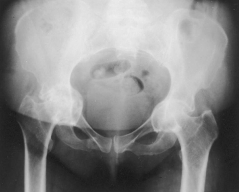
The principles of reconstruction of a protrusion deformity are as follows: (1) the hip center must be placed in an anatomic location to restore proper joint biomechanics; (2) the intact peripheral rim of the acetabulum should be used to support the acetabular component; and (3) the remaining cavitary and segmental defects in the medial wall must be reconstructed, preferably with bone grafting ( Fig. 3.82 ). Determining the anatomic location of the hip center and the degree of migration caused by progressive protrusion can be difficult. Variations in the amount of flexion and rotation of the pelvis may distort radiographic measurements. Ranawat, Dorr, and Inglis proposed a method of determining the hip center by the radiographic relationships of the Kohler and Shenton lines and the height of the pelvis. Although this method is useful for radiographic measurement, it offers no assistance in correcting the hip center to the anatomic location during surgery. Generally, the relationship of the prosthetic socket to the remaining acetabular rim and the measurement of the remaining medial and superior bony deficits in comparison to the preoperative templating assist in bringing the hip center to a more lateral and inferior position. The adequacy of correction of the deformity correlates with long-term prosthetic survivorship.
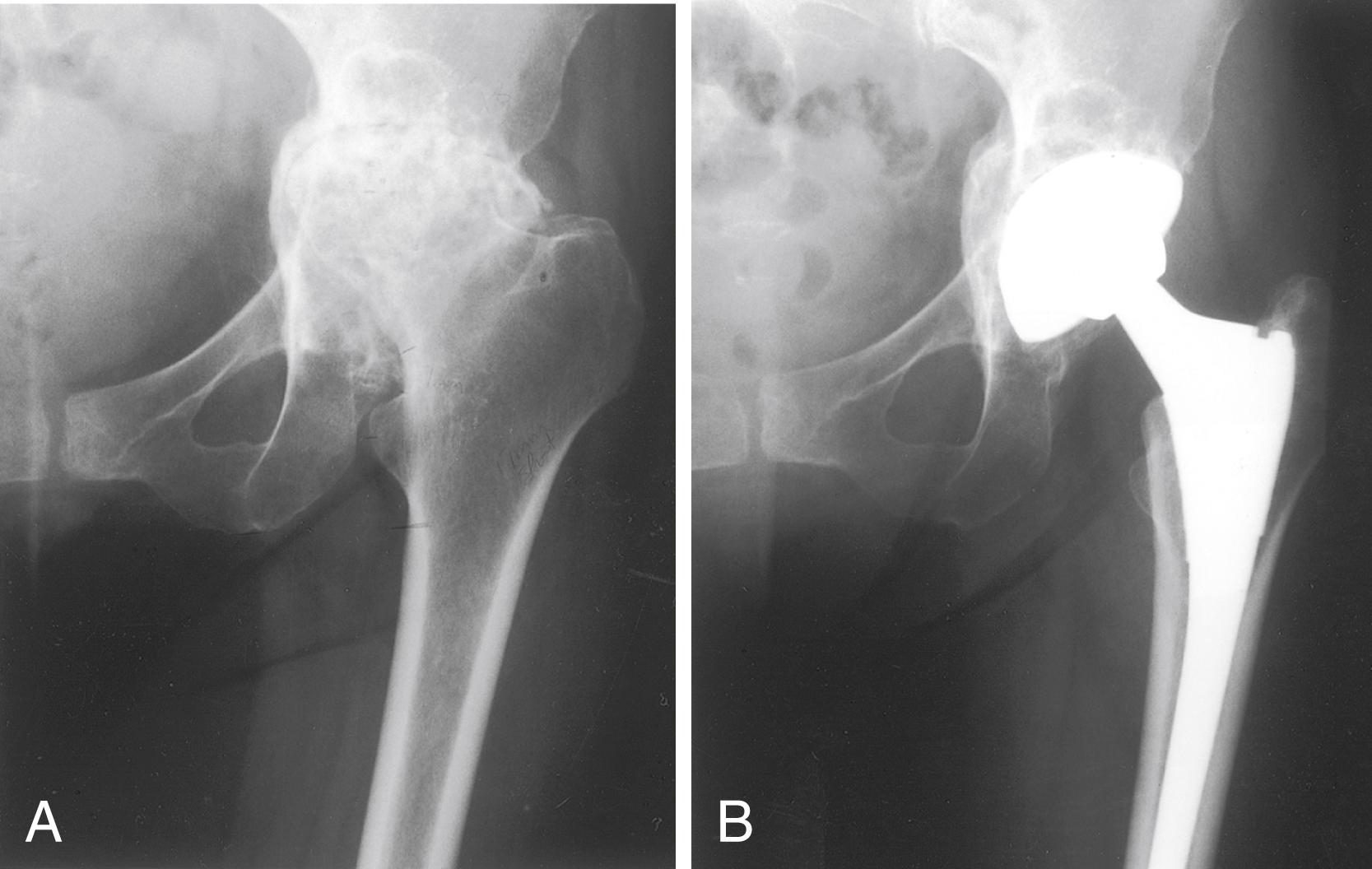
Often, because of the medial migration of the femur, the sciatic nerve is nearer the joint than normally, and consequently it should be identified early in the operation and protected. Trochanteric osteotomy occasionally may be required for exposure. Dislocation of the hip can be extremely difficult, and removal of a small overhanging portion of the posterior acetabular wall may facilitate dislocation. In severe cases, the femoral head is incarcerated within the acetabulum and dislocation is impossible. In this instance, the femoral neck must be osteotomized in situ at the appropriate angle. Considerable capsular release is necessary to deliver the proximal end of the femur out of the depth of the wound. The femoral head is removed from the acetabulum with a corkscrew or a threaded pin. If it is more firmly fixed in the acetabulum, it is sectioned and removed piecemeal. The medial wall of the acetabulum usually is thin or may be partly membranous, and it should not be penetrated. Medial reaming is unnecessary; instead, the cartilage and soft tissues are removed with a curet. The smooth, sclerotic floor is roughened with a curet or chisel, but penetrating into the pelvis is avoided.
The peripheral rim of the acetabulum is intact when a protrusio deformity occurs. This rim can be relied on to provide stability for a cementless socket but must be prepared carefully. When the femoral head has protruded into the pelvis, an “hourglass” deformity is created and the walls of the periphery of the acetabulum diverge ( Fig. 3.83A ). If only the periphery of the acetabulum is reamed to a larger size, the walls can be made to converge. The acetabular component is stabilized on the reshaped rim, and the thin or deficient medial wall is not relied on to prevent recurrent deformity. Reaming is begun with the largest size reamer that fits comfortably into the opening of the acetabulum. The reamer is advanced only until it is flush with the rim, and the medial wall is not reamed. Progressively larger reamers are inserted in the same manner until a convergent rim is created that is wide enough to support the acetabular component ( Fig. 3.83B ). The anterior and posterior walls are palpated frequently during reaming to avoid excessive bone removal or the creation of a complete segmental defect in the anterior or posterior wall. Any segmental or cavitary deficit that remains medially is grafted with particulate cancellous bone, wafers, or a solid graft from the femoral head and impacted by using the last reamer, turning it in the reverse direction for a few turns. A component 1 to 2 mm larger than the final reamer size improves stability on the prepared rim ( Fig. 3.83C ).
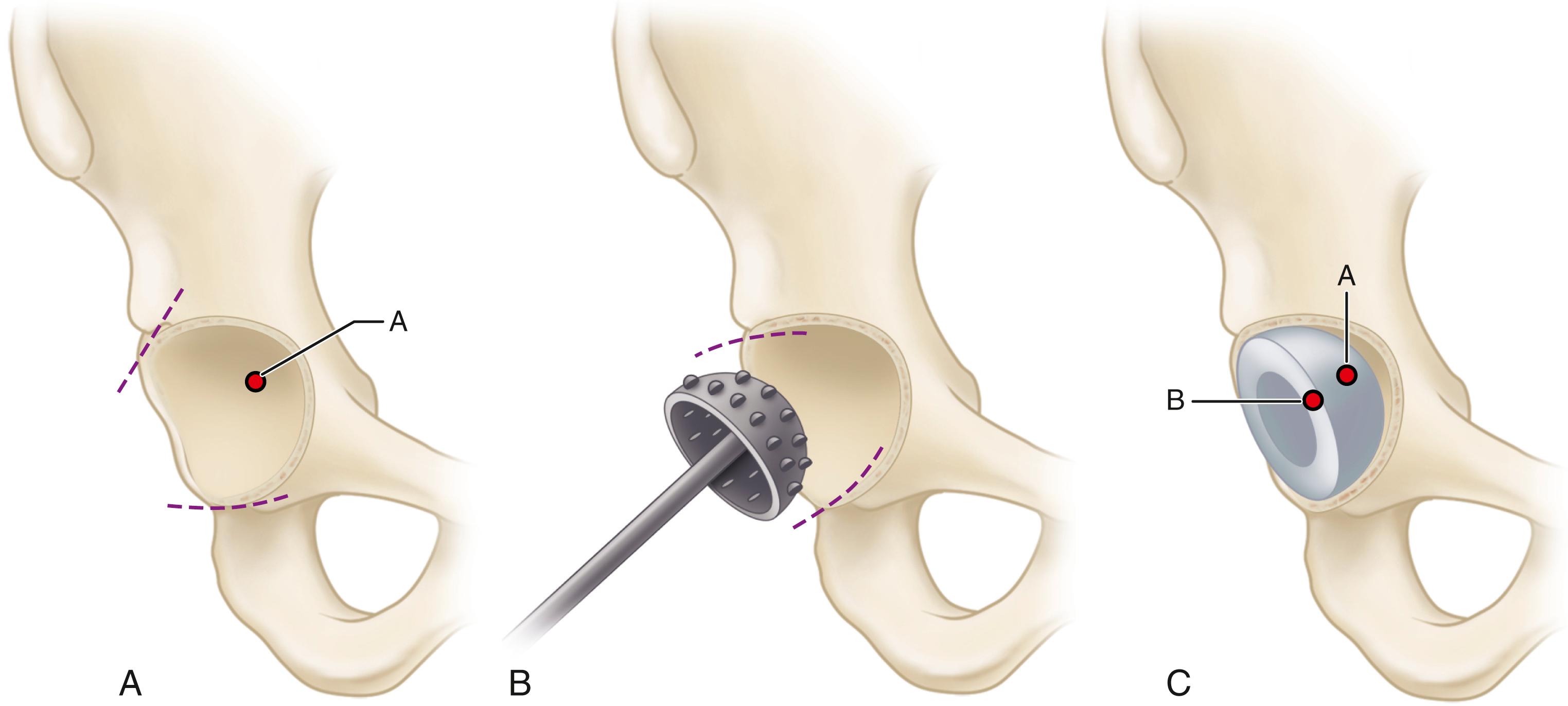
Sloof et al. popularized the technique of impaction grafting of the acetabulum for correction of protrusio associated with rheumatoid arthritis and revision procedures. Particulate cancellous bone grafts measuring 0.5 to 1.0 cm are tightly impacted into the medial acetabular defects, and a segment of wire mesh is placed on top of the bone graft. A conventional acetabular component is cemented into the construct. Weight bearing is limited for 3 months. In a series of 36 hips with protrusio caused by rheumatoid arthritis, Sloof et al. reported a survival rate of 90% at 12 years with the impaction grafting technique. Although this technique has not been widely used, Sloof’s approach has been adapted for use in the femur in revision procedures and has gained more widespread acceptance (see Technique 3.31). In a series of 20 hips with protrusion deformity due to rheumatoid arthritis, Zhen et al reported no acetabular fractures with this technique despite the thin, osteopenic acetabular rim.
Surgical correction of protrusio acetabuli often entails significant lengthening of the limb. Patients with bilateral deformity should be advised of this before surgery. The lengthening occurs on both sides of the joint; the center of the acetabulum is brought to a more inferior and lateral position, and the femoral side is lengthened because of the prior varus deformity of the femoral neck. We have found a low-level femoral neck resection coupled with a femoral component with enhanced offset (see Fig. 3.16 ) to be helpful in minimizing limb lengthening while maintaining adequate joint stability (see Fig. 3.82 ).
In surgery for developmental dysplasia of the hip, proper patient selection is crucial. Pelvic or periacetabular osteotomy should be considered in young patients with retained cartilage space on radiographs. THA still is often required for patients with symptomatic arthritis secondary to dysplasia.
The complexity of the reconstruction is influenced by the degree of anatomic abnormality ( Fig. 3.84 ). The classification of Crowe et al. has been used to describe the degree of dysplasia and is based on the magnitude of proximal femoral migration relative to the acetabulum as measured on an anteroposterior radiograph of the pelvis. The migration is calculated by measuring the vertical distance between the interteardrop line and the medial head-neck junction of the involved hip. The degree of subluxation is the ratio of this distance to the vertical diameter of the opposite femoral head. If the distance from the medial head-neck junction to the interteardrop line is half the vertical diameter of the opposite femoral head, the degree of subluxation is 50%. In patients in whom the opposite femoral head also is deformed, the vertical diameter of the femoral head is estimated as 20% of the height of the entire pelvis as measured from the top of the iliac crest to the bottom of the ischial tuberosities. Dysplastic hips are classified by the amount of subluxation: type I, less than 50%; type II, 50% to 75%; type III, 75% to 100%; and type IV, greater than 100% subluxation.
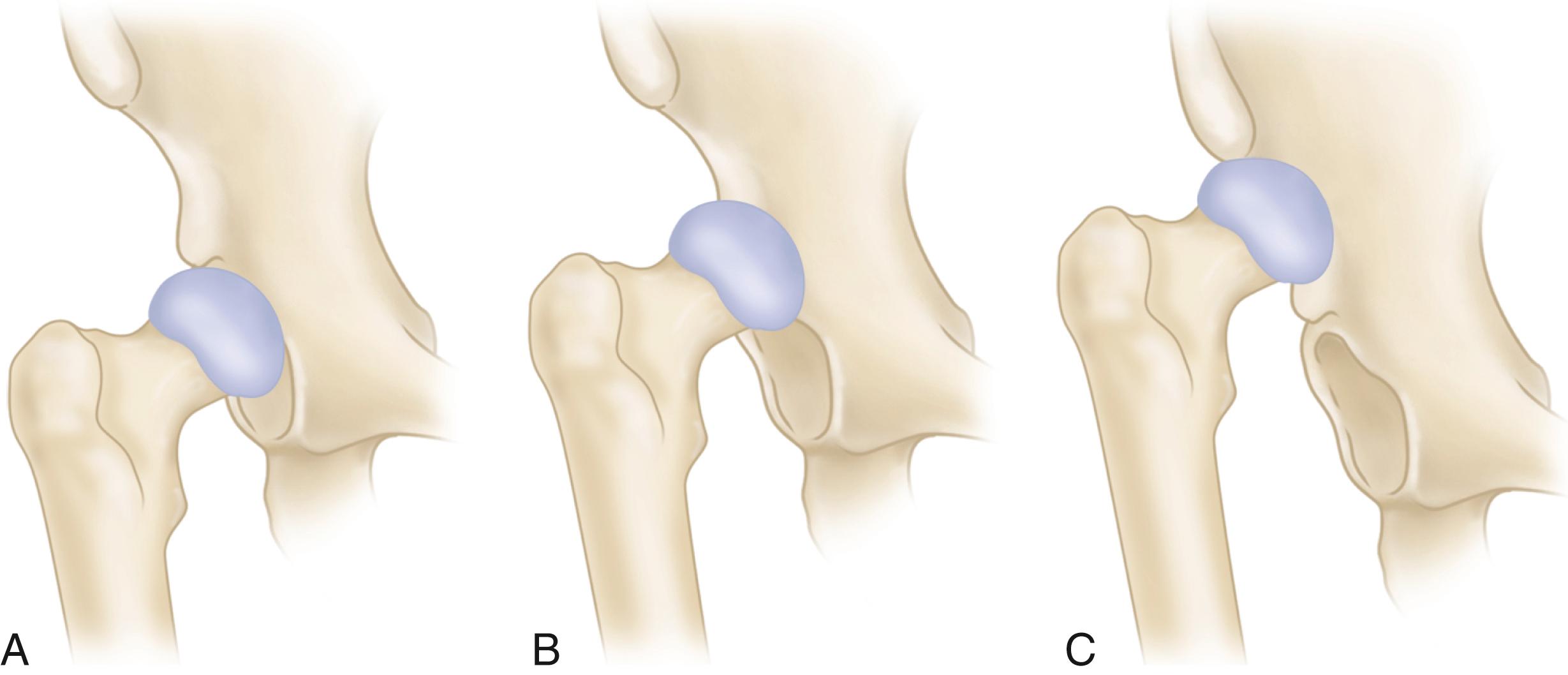
In addition to the proximal migration of the femur, several deformities of the bone and soft tissues are of surgical importance. The femoral head is small and deformed; the femoral neck is narrow and short, with varying but often marked anteversion. The greater trochanter usually is small and often located posteriorly. The femoral canal is narrow; Dunn and Hess found its average width 2 cm inferior to the lesser trochanter to be only 1.5 cm. The narrowness of the femur and the increased anterior bowing of the proximal third make canal preparation difficult. If the femoral head has subluxated and migrated proximally, the acetabulum is oblong and its roof is eroded. In high and intermediate dislocations, the impingement of the femoral head on the ilium stimulates the formation of a false acetabulum that usually is not deep or wide enough for containment of the cup. The thickest bone available usually is in the true acetabulum, and the cup should be implanted there if possible ( Fig. 3.85 ).
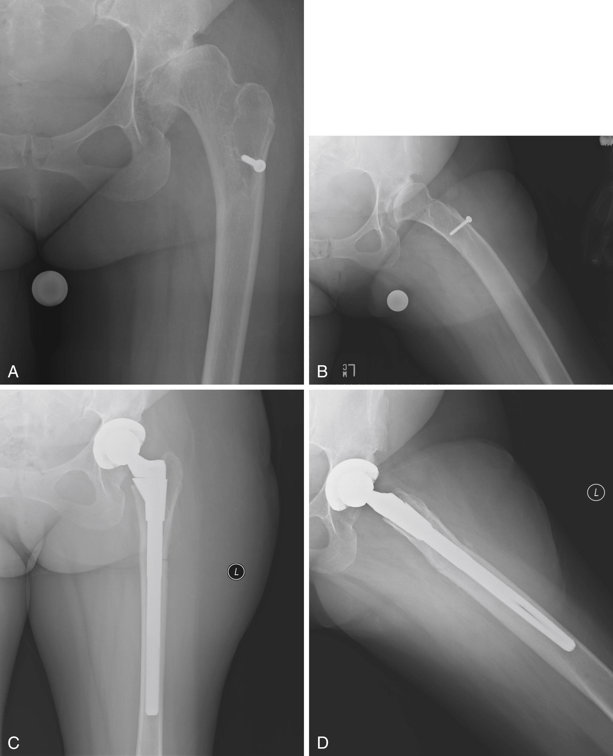
The abductor muscles frequently are poorly developed and oriented more transversely than normal. The adductors, psoas, hamstrings, and rectus femoris muscles usually are shortened. The capsule is elongated and redundant. Extensive capsulectomy and tenotomy of the psoas, rectus femoris, and adductors may be required to correct the deformity. The sciatic nerve has never assumed its normal length and is susceptible to stretch injury when the bony and soft-tissue deformities are corrected.
Before surgery, anteroposterior radiographs of the pelvis and proximal femur and a lateral view of the femur must be studied carefully to determine the amount of bone available in which to fix the cup, the level at which it should be fixed, the problems likely to be encountered in reaming the femoral canal because of the anterior bowing and narrow width, the need for a femoral osteotomy, and the size and type of components to be used. In patients with unilateral dislocations, lengthening of the affected extremity during surgery is desirable to correct some or all of the discrepancy in limb lengths. No more than 3 to 4 cm of lengthening should be planned. The leg lengthening often is offset to some extent by the necessity of shortening the femur to place the femoral head in the true acetabulum.
The shallow dysplastic acetabulum may require a very small acetabular component (≤40 mm). Implants of this size are not typically part of the standard implant sets and may need to be specially ordered. A 22-mm femoral head size should be used because it can be difficult to maintain adequate polyethylene thickness when a larger head size is used with a small cup. Charnley and Feagin warned that no more than 5 mm of the cup should protrude beyond the bone. If possible, the entire cup should be confined within the bone, and the medial wall of the acetabulum should be left intact. Intentional fracture of the medial wall or penetration of the medial wall with reamers to obtain lateral coverage has been proposed, but this is not universally accepted.
Most authors recommend placement of the acetabular component within the true acetabulum (see Fig. 3.85 ), rather than leaving the center of rotation in a superiorly displaced position with the cup in a false acetabulum ( Fig. 3.86 ). This medial and inferior location diminishes joint contact forces compared with the superior and laterally displaced position of a false acetabulum. In addition, placement in the true acetabulum facilitates limb lengthening, improves abductor function, and in most cases places the acetabular component in the best available bone stock. Long-term studies have found the frequency of loosening to be two to three times higher when the cup is placed outside the true acetabulum than when it is initially positioned within the true acetabulum.
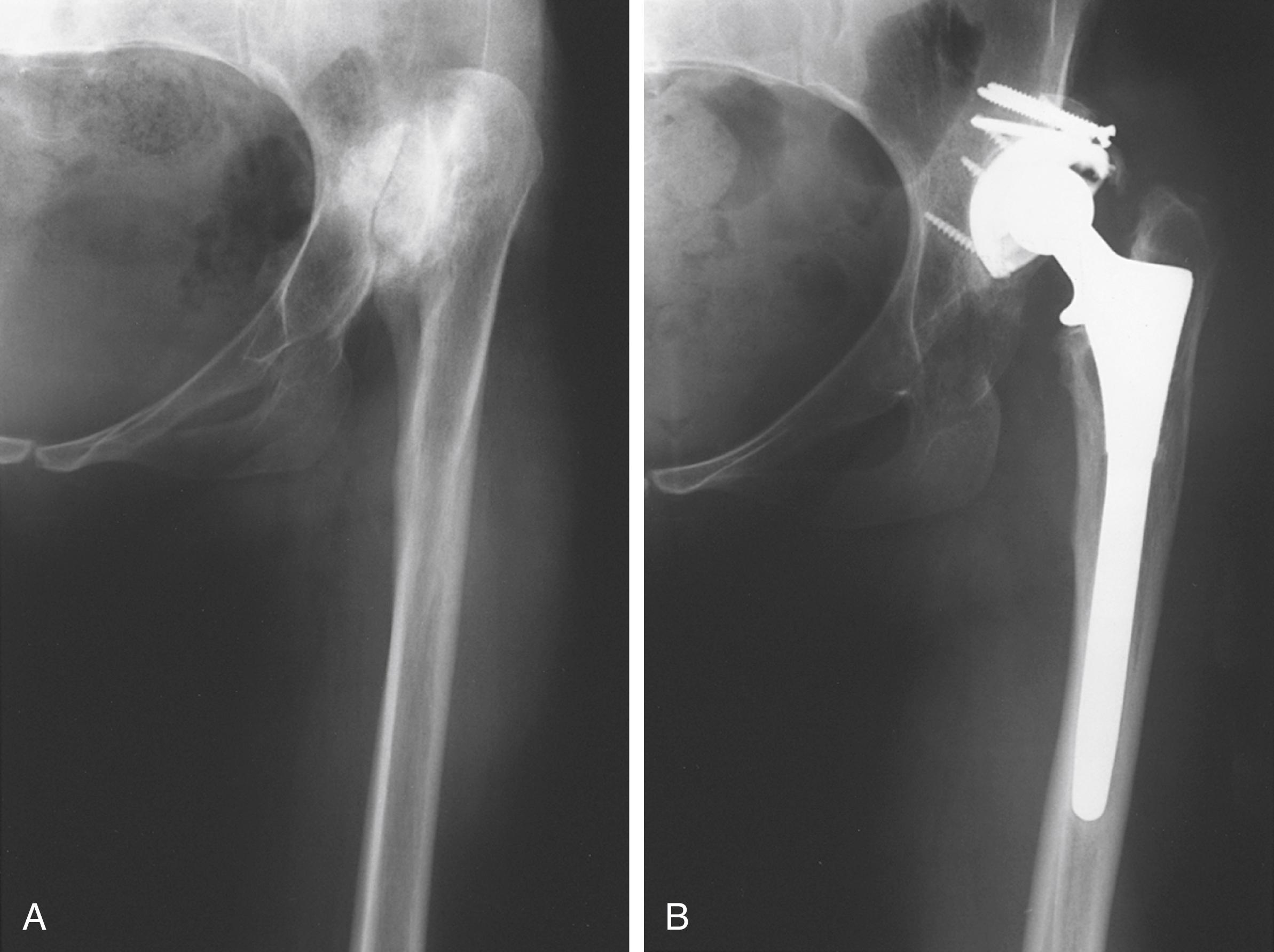
With Crowe type I hips, there is relatively little bony deformity, and the acetabular component can be placed in the true acetabulum without difficulty. Medialization to the floor of the acetabulum provides adequate containment of a standard component. In Crowe type II and type III hips, when the socket is placed within the true acetabulum, a large superior segmental deficit remains with a lack of superior coverage of the component ( Fig. 3.87 ). In most patients, grafting is not required if the acetabular component is placed in a slightly high location as long as it is not also lateralized.
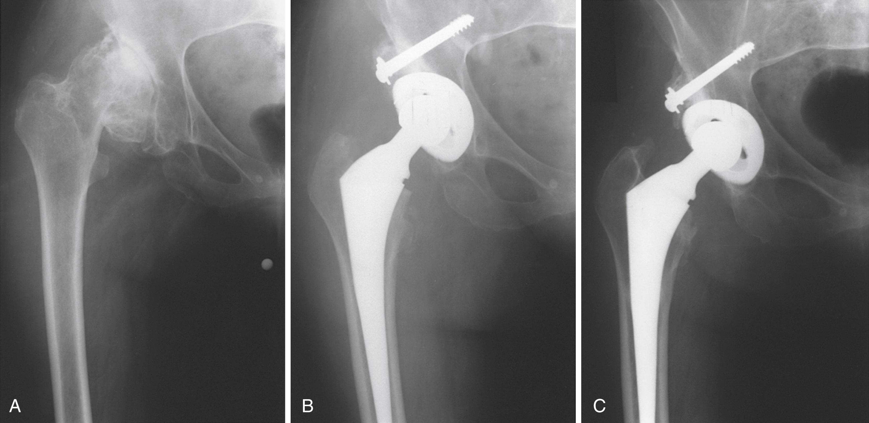
Although early reports of acetabular grafting showed acetabular loosening in as many as 47%, other reports of bulk acetabular bone grafting in developmental dysplasia of the hip have been more positive, with loosening in approximately 15%.
Technique is most important in achieving success with solid acetabular bone grafts. All cartilage and soft tissue are removed from the contact areas between donor and host bone. The fit of the graft to the host is crucial; the head is placed in the defect in its most congruous position. The graft should be positioned beneath a buttress of host bone that is capable of supporting weight bearing, and the trabeculae of the graft should be oriented in line with the weight-bearing forces. The graft is provisionally fixed with smooth Kirschner wires. Definitive fixation is achieved with two or three cancellous lag screws with washers. The screws should be oriented in parallel and along lines of weight-bearing forces. Screws must be inserted with careful interfragmentary technique, and the graft should be overdrilled to allow this if necessary. Initial shaping of the graft is done with a high-speed burr. Final shaping of the graft and remaining host acetabulum is done with hemispherical reamers. Caution must be exercised during reaming to avoid excessive torque on the graft. For this reason, we prefer to prepare and ream the graft before definitive screw fixation ( Fig. 3.88 ). In this way, the final sites for screw fixation are selected after the graft has been prepared and are not compromised during the reaming process. Final shaping of the lateral aspect of the graft also can be done at this point with a trial acetabular component in place before final screw fixation. If a portion of the graft is left prominent beyond the lateral edge of the cup, the unstressed portion likely will be resorbed over time ( Fig. 3.89 ).
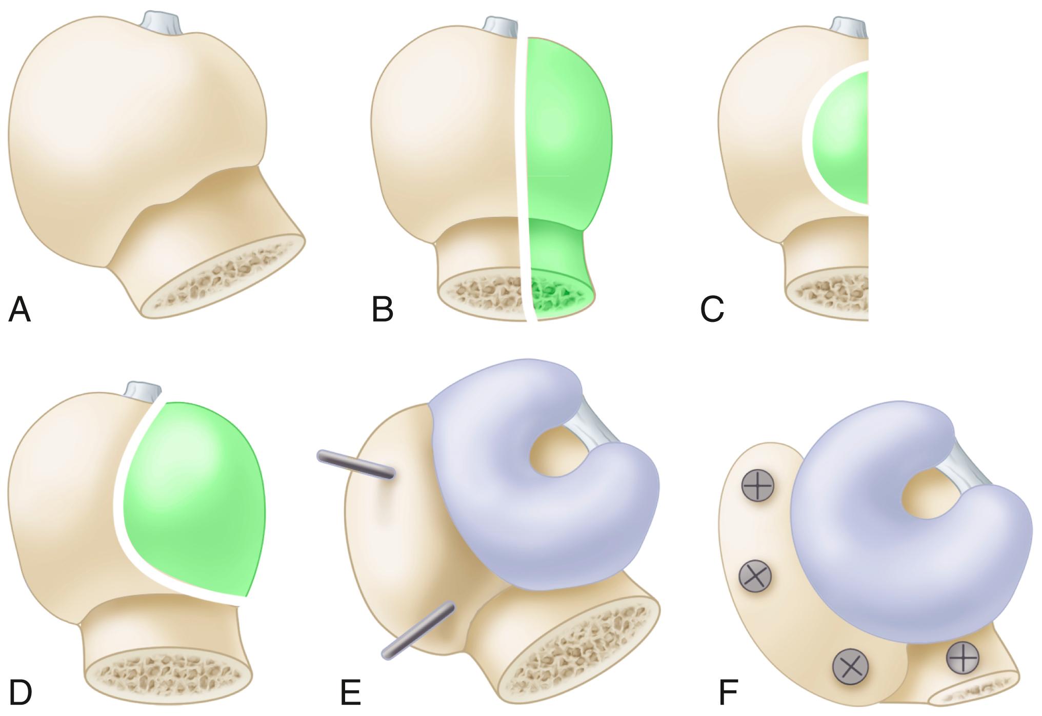
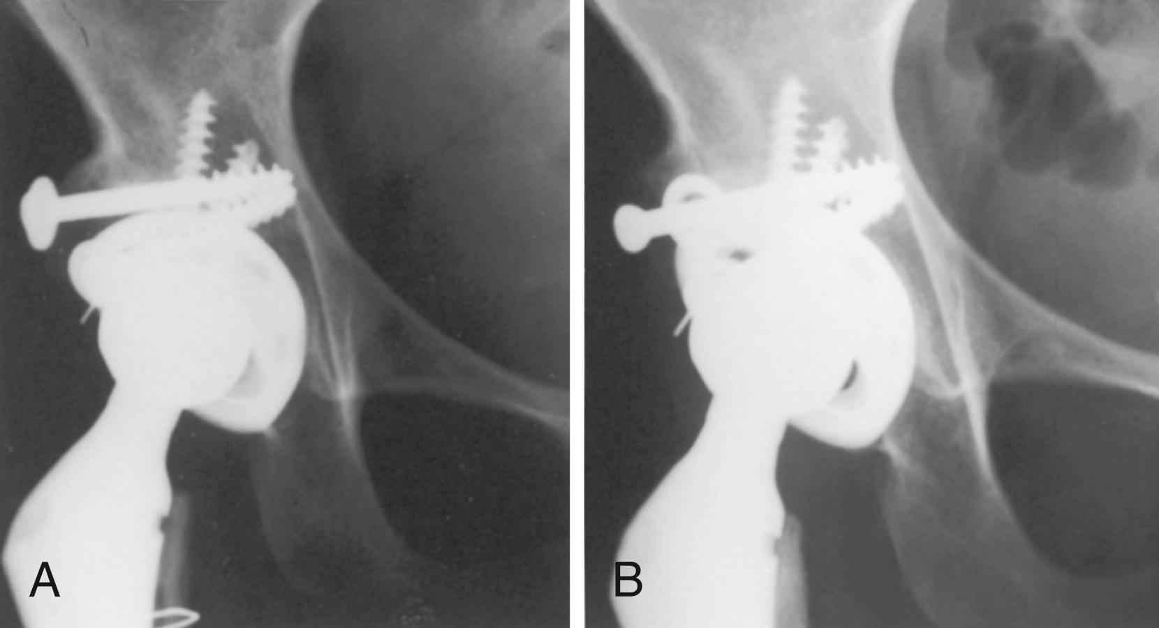
The rate of union and resorption and the long-term viability of acetabular grafts are concerns. Sanzén et al. found no incorporation of cortical bone grafts. Limited resorption of the lateral aspect of the graft occurred in 20 of 32 hips, but resorption involving bone supporting the socket occurred in only three hips (see Fig. 3.89 ). Radioisotope scanning did not correlate with bone resorption, nonunion, or loss of bone structure. In most reported cases of acetabular loosening after bulk acetabular bone grafting, the graft was viable and revision was accomplished without the need for additional bone grafting.
There is no potential for bone ingrowth from bulk acetabular grafts. The amount of the component that must be placed in contact with viable host bone for long-term stability remains to be determined. This problem and the failure of large bulk grafts led Harris to advocate placement of a small, porous acetabular component at a superiorly displaced position. Isolated superior displacement or superomedial displacement results in only limited increase in joint contact forces. In reconstructing a hip with a so-called high hip center, a larger amount of the porous surface can be placed against viable host bone. When a small socket is placed in a superior and medial position, however, femoral-pelvic impingement and instability become problems. Resection of a large amount of bone from the anterior column adjacent to the superior pubic ramus and from the ischium often is required to allow motion and reduce the risk of dislocation. Some degree of superior displacement of the hip center is acceptable. Nawabi et al. found no loosening when the hip center was approximately 1 cm higher than the anatomic position, but found a higher wear rate in hips in which the center was left in a lateralized position. Utilizing highly crosslinked polyethylene, Galea et al. found no acetabular loosening and low wear in 123 hips with a high hip center.
With a high dislocation, as in Crowe type IV, the acetabulum is hypoplastic, but its superior rim has not been eroded by the femoral head. The reconstruction usually can be done with a conventional, albeit very small acetabular component placed within the true acetabulum and without structural bone grafting. When the hip is initially exposed, the femoral head is dislocated from a false acetabulum and the site of the true acetabulum may not be immediately apparent. A ledge of bone usually separates the true acetabulum from the false one, and it should be used as a landmark from which dissection is carried inferiorly. The transverse acetabular ligament usually can be located along with the cotyloid fossa, retaining some atrophic fat from the pulvinar. A retractor placed inferior to the transverse ligament and into the obturator foramen ensures that the dissection has been carried far enough inferior to place the component in the true acetabulum. The depth of the acetabulum often is deceptive because it is filled with bone. Removal of the pulvinar exposes the depth of the cotyloid fossa and the medial wall of the acetabulum, allowing the surgeon to determine the amount of medialization that can be safely accomplished by reaming. If the cotyloid fossa is not apparent, a hole can be drilled and a depth gauge used to determine the thickness of the available bone. The anterior wall of the acetabulum often is thin and can be penetrated easily, but the posterior wall usually is adequately thick. When enlargement of the acetabulum from anterior to posterior is necessary, more bone is resected from the posterior wall than from the anterior wall. Any reaming must be done with care so as not to compromise the rim of the acetabulum or penetrate the medial wall. The bone is often very soft, and the final reamers may be used in reverse to enlarge the acetabulum by impaction rather than removal of bone.
Transacetabular screw fixation of the acetabular component usually is required because of rim deficiencies and osteopenia. Liu et al. used three-dimensional CT to simulate placement of the acetabular component within the true acetabulum in hips with Crowe type IV dysplasia and found that the center of rotation shifted anteroinferiorly. Consequently, the “safe zone” for screw placement (see Fig. 3.46 ) is narrower. Screws placed in the medial portion of the posterosuperior quadrant risk injury to the obturator vessels.
When the center of the acetabulum has changed little, as with Crowe type I and type II dysplasias, femoral length is not problematic and the femoral reconstruction generally is straightforward. Small-diameter cemented or cementless stems generally are satisfactory. The femoral component must be placed in neutral or slight anteversion in relation to the axis of the knee joint. Marked anteversion of the femoral neck can be misleading when positioning the femoral component, and anterior instability may occur, particularly if the acetabular component has been placed in additional anteversion. Excessive femoral anteversion can be corrected with a modular cementless femoral component that can be rotated into any degree of version (see Fig. 3.26 ). This does not correct the posterior displacement of the greater trochanter, however, which may cause impingement in external rotation.
For Crowe type III and type IV hips, femoral length is more problematic. When the prosthetic socket has been placed in the true acetabulum, the femur must be translated distally several centimeters to reduce the prosthetic femoral head into the acetabulum. Often the tissues most limiting this distal translation are the hamstrings and rectus femoris rather than the abductors. In such cases, a femoral shortening osteotomy allows reduction of the femoral head into the true acetabulum without extensive soft-tissue release. Osteotomy of the greater trochanter and resection of 2 to 3 cm from the proximal femoral metaphysis may be necessary to permit reduction of the joint without causing undue tension on the sciatic nerve or fracture of the femoral shaft ( Fig. 3.90 ). As described by Dunn and Hess, the bone should be resected 0.5 cm at a time, and trial reductions are repeated until enough shortening is obtained to reduce the hip without undue soft-tissue tension. The narrow canal and the resection of the metaphyseal flare of the femur often require the use of a component with a small, straight stem.
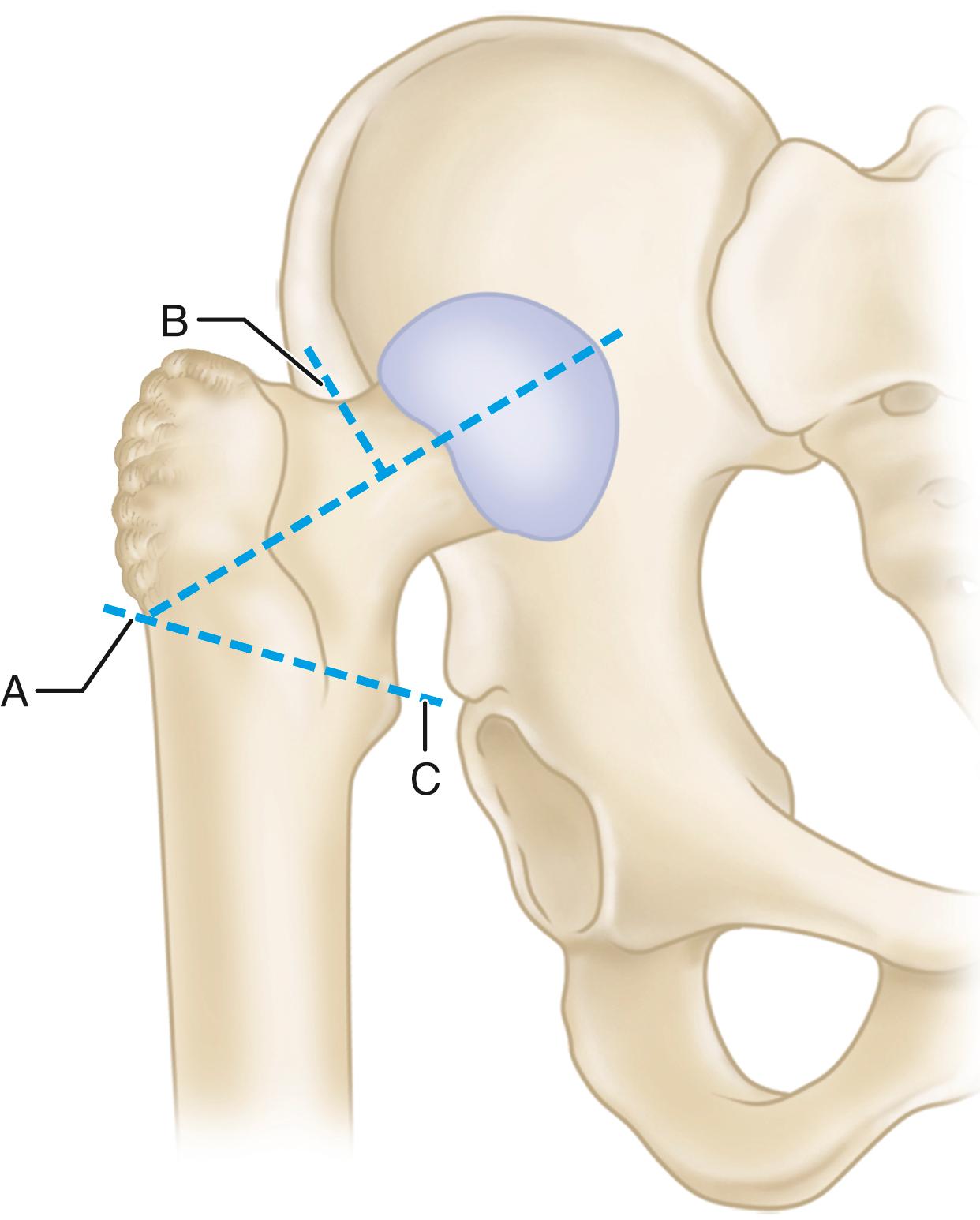
Sponseller and McBeath described a technique of subtrochanteric femoral shortening using the femoral component for intramedullary fixation. This approach allows correction of excessive femoral anteversion along with the posterior displacement of the greater trochanter while avoiding trochanteric osteotomy and the potential for nonunion. The architecture of the proximal femoral metaphysis is preserved, and the orientations of the greater trochanter and abductors are corrected to restore hip mechanics and prevent instability and limp. A standard stem design also can be used. Additionally, the level of the femoral osteotomy provides excellent exposure of the acetabulum if structural bone grafting is required ( Fig. 3.91 ). The femur is provisionally prepared with reamers and broaches before the femoral osteotomy. The depth of reaming of the distal canal should take into account the length of the segment of femur that will be removed in the shortening. The osteotomy is made just distal to the lesser trochanter, and the two fragments are retracted anteriorly for acetabular preparation and implantation. A trial reduction is then carried out with the femoral component in the proximal fragment alone. Traction is applied to the distal femoral fragment, and the overlapping portion is resected from the distal fragment. Final preparation of the distal fragment is then carried out. A larger diameter stem may be required to obtain a tight fit after removing the segment from the femur. The two fragments are reduced, the proximal fragment is derotated to 10 to 15 degrees of anteversion, and the osteotomy site trimmed for optimal apposition. The final stem is implanted, maintaining the proper rotation of the fragments and the implant. The stem must be rotationally stable within both fragments to ensure union. Prophylactic cerclage wiring of the distal fragment (or both fragments) helps prevent fractures, because a very tight fit is required. The resected portion of femur can be bivalved and placed over the osteotomy as onlay grafts. Becker and Gustilo reported using a chevron-shaped osteotomy to improve rotational stability. A short oblique or step-cut osteotomy fixed with cerclage wires also provides greater rotational stability than a transverse osteotomy but adds a degree of technical difficulty. Muratli et al. investigated multiple osteotomy configurations in composite femurs. None proved superior in stability and the application of strut grafts did not make a significant contribution to stability. Sofu et al. reported nonunion in 4 of 73 patients when a cable plate was used for osteotomy stabilization in conjunction with a tapered femoral component. We have used a modular stem with distal flutes to gain rotational stability with a simple transverse osteotomy, and union has been reliable ( Fig. 3.92 ).
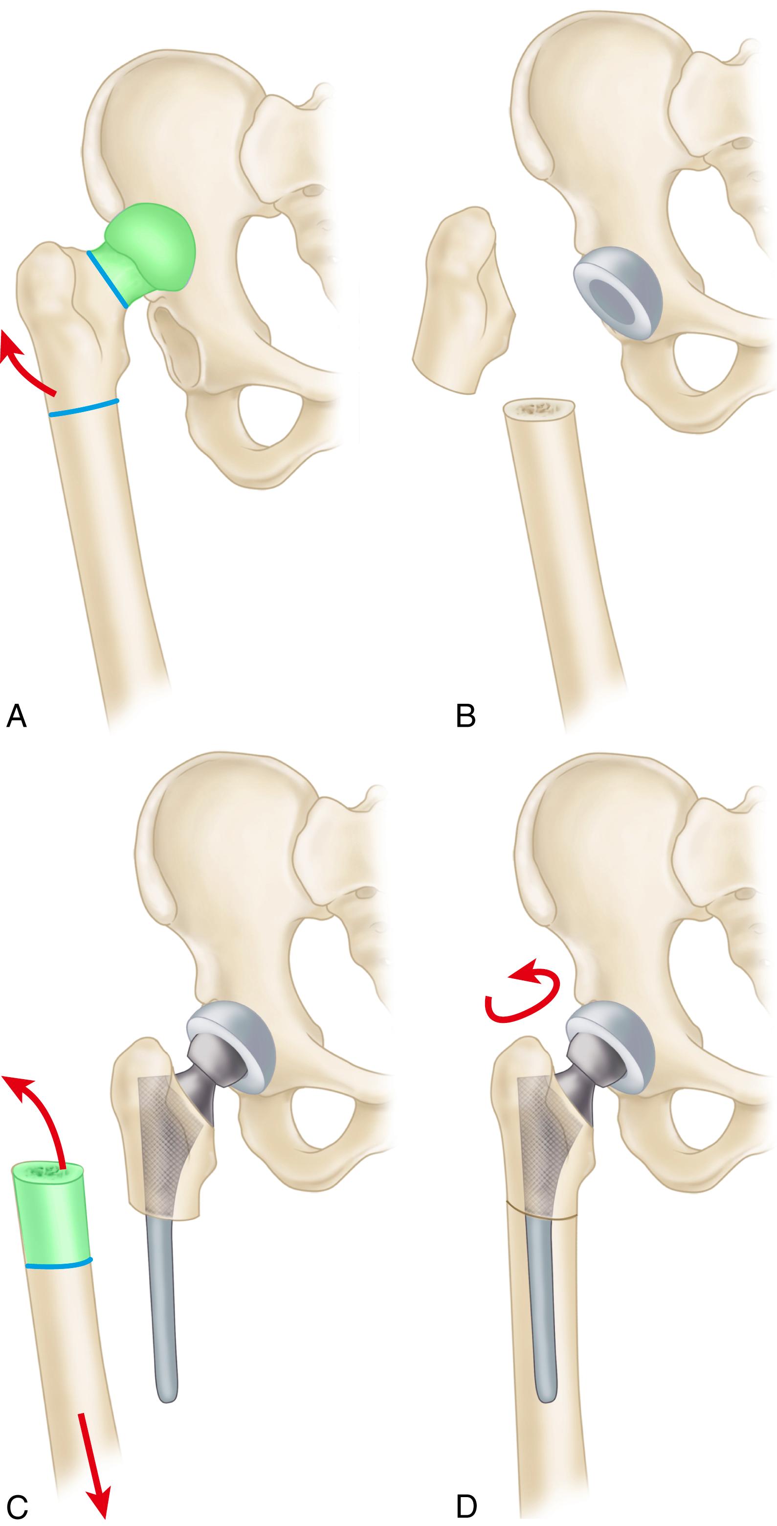
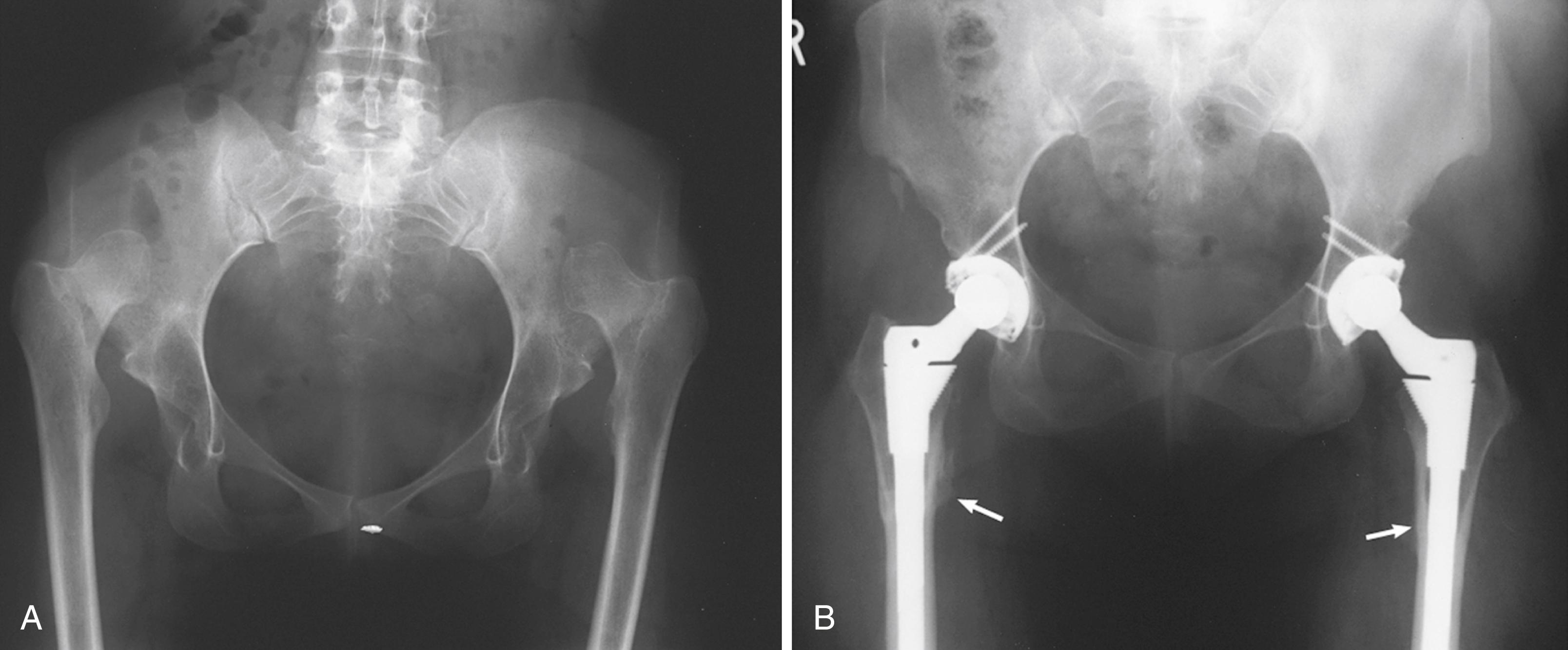
In most cases, THA can be performed without osteotomy of the trochanter, but if at the end of trial reduction the trochanter impinges on the pelvis when the hip is abducted, it should be osteotomized and reattached distally. In addition, if the trochanter is posterior and impinges on the posterior aspect of the acetabulum during external rotation, it must be osteotomized and reattached more laterally. Abduction is improved when a stem with greater offset is used; there is less tendency for impingement ( Fig. 3.93 ).
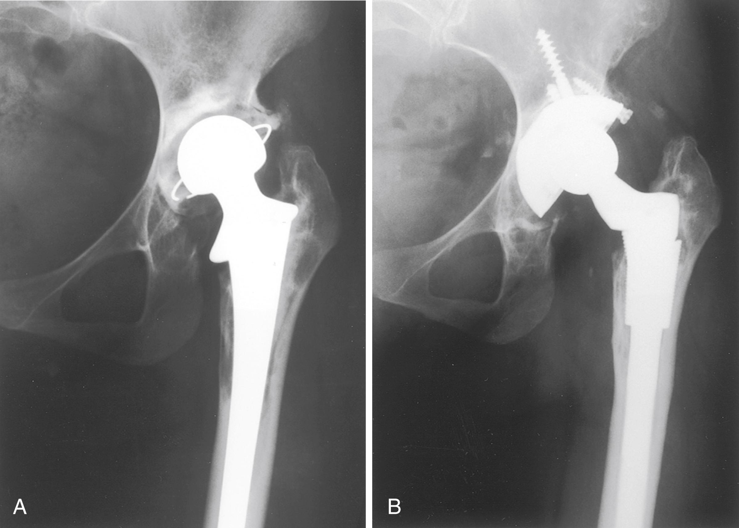
The results of THA in selected patients with dysplastic or intermediate dislocation of the hip have been satisfactory for stability, mobility, and pain relief. With high dislocations, a Trendelenburg gait and some limitation of motion usually persist, however. The survivorship of cemented arthroplasty in dysplastic hips is inferior to that of other groups because of the young age of the patients and the complexity of the procedures. Early and midterm cementless results seem more promising. In a series of 28 Crowe IV hips requiring femoral shortening osteotomy, Ollivier et al. reported 10-year survivorship free of revision for aseptic loosening of 89%. The chief complications in most series have been intraoperative femur fracture, dislocation, and sciatic nerve injury (see the section on complications).
The potential for Legg-Calvé-Perthes disease (LCPD) to cause symptomatic secondary osteoarthritis has long been recognized. Froberg et al. found that 13% of patients with LCPD eventually required hip arthroplasty; the prevalence was highest in patients with more severe head involvement.
The sequelae of LCPD include anatomic abnormalities that may impact the performance of hip arthroplasty. The acetabulum often is dysplastic and may be retroverted, although grafting is seldom required as with developmental dysplasia. The limb is shortened due to coxa vara deformity, and the greater trochanter is increased in height. Femoral neck version abnormalities may result from the disease process or prior reconstructive surgery. Often there is a size mismatch between the metaphyseal and diaphyseal regions of the femur, which makes fixation more difficult with conventional cementless femoral components.
Hanna et al. carried out a meta-analysis of 245 hips operated for sequelae of LCPD. The revision rate at a mean of 7.5 years was 7% and complications included intraoperative fracture and sciatic nerve palsy with lengthening. Fractures were less common when a modular stem design (see Fig. 3.26 ) was used.
Patients with adolescent slipped capital femoral epiphysis (SCFE) may develop secondary osteoarthritis due to femoroacetabular impingement with abnormal hip mechanics. Arthroplasty also may be required due to osteonecrosis or chondrolysis following surgery for fixation of the neck. Deformity of the femoral neck with retroversion may occur because of the disease process. Antiquated fixation devices placed in adolescence may become completely encased in cortical bone, making their extraction difficult.
In a report from the New Zealand National Joint Registry, Boyle, Frampton, and Crawford found no difference in outcomes between patients with SCFE and primary osteoarthritis undergoing hip arthroplasty.
Dwarfism is typically defined as having a height of less than 147 cm (4 ft 10 in) and can result from a variety of endocrine disorders such as growth hormone deficiency, achondroplasia, and skeletal dysplasias. Premature osteoarthritis of the hip often is seen in skeletal dysplasias because of abnormalities of articular cartilage, arrested joint development, and altered mechanics. The problems encountered in THA in short-statured individuals ( Fig. 3.94 ) are similar to those encountered in persons with hip dysplasia. Excessive femoral bowing is common, and the femoral canal may be wide proximally but narrow distally, creating a mismatch. Many patients have had prior surgery, including osteotomy that may complicate arthroplasty further. Thorough preoperative planning is imperative. Often, special miniature femoral components are necessary because of the narrow canal and femoral osteotomy or customized short stems may be required to accommodate femoral bowing. Cups with small outside diameters are necessary. CT of the pelvis and femur is helpful in delineating abnormal bony anatomy and size and in determining whether custom implants would be necessary.
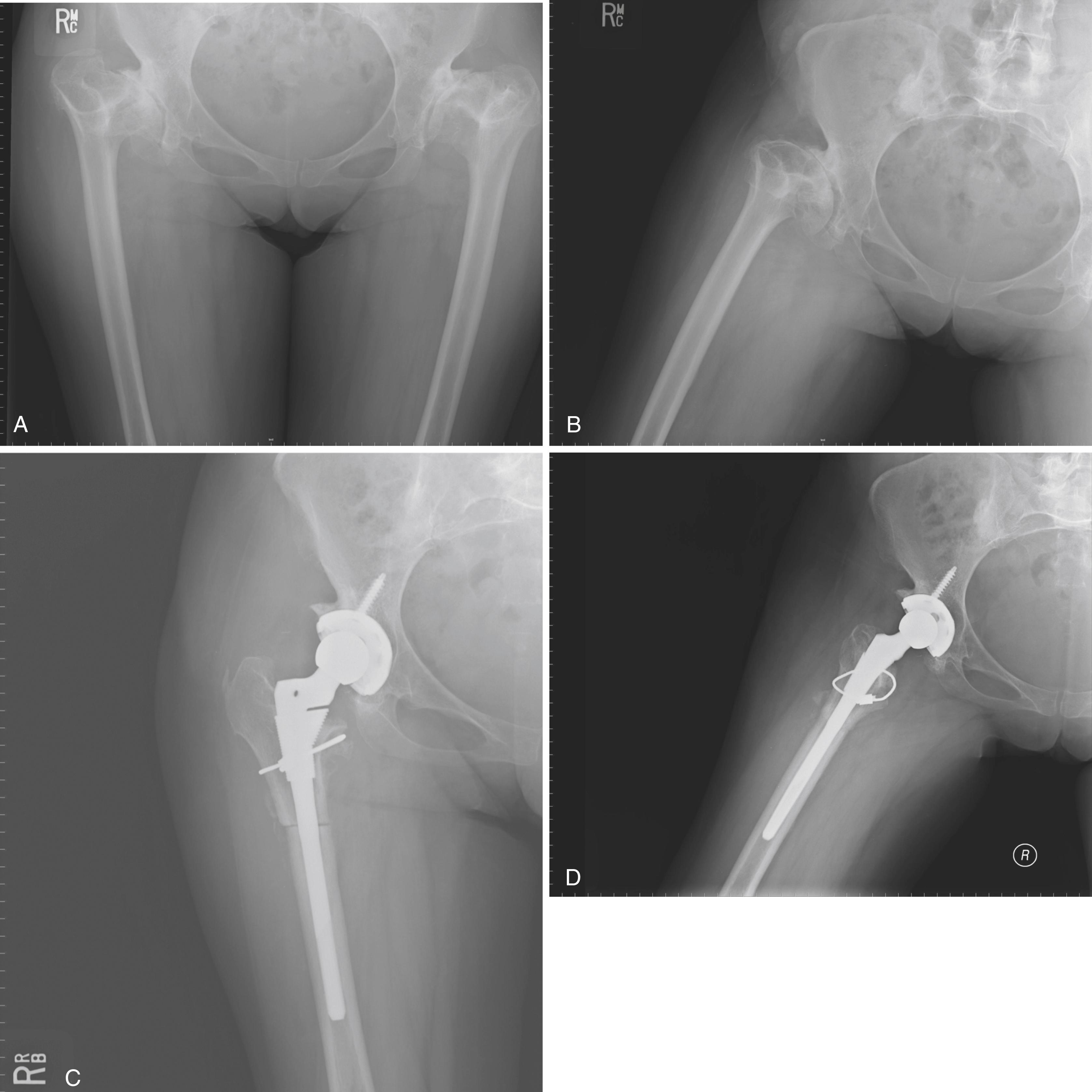
Many syndromes that cause short stature involve other joints, including the cervical spine, which may be unstable. Lumbar deformities also may cause referred pain in the hip and should be investigated before hip surgery. Knee instability also may bring about the need for future knee arthroplasty with stemmed implants; therefore, a long-stem femoral component for the hip arthroplasty should be avoided if possible.
Survivorship in this challenging group of patients is worse than in those with osteoarthritis. In a series of 102 hips in patients with dwarfism, Modi et al. found 10-year survivorship of 80.7%. Failures were related to postoperative femoral and acetabular fracture and wear of noncrosslinked polyethylene.
Conventional fracture fixation techniques and hemiarthroplasty traditionally have been recommended for displaced, acute fractures of the femoral neck. THA has been perceived as excessively costly, with a higher risk of dislocation. Recent evidence suggests the management of acute femoral neck fractures should be reevaluated.
A number of randomized controlled trials are available comparing internal fixation, hemiarthroplasty, and THA. In a multicenter study of 450 patients, Rogmark et al. reported 43% failures with internal fixation compared with 6% with arthroplasty. Arthroplasty patients also had better walking ability and less pain, but dislocation occurred in 8%. Blomfeldt et al. randomized 120 cognitively normal patients to either hemiarthroplasty or THA. Blood loss and operative time were higher in the total hip group, but there were no differences in complication rates or mortality. Harris hip scores were higher in the total hip group at both 4 and 12 months. All patients had the same anterolateral approach, and there were no dislocations in either group. In a 4-year follow-up of this same series of patients, Hedbeck et al. found that these differences persisted and increased, favoring total hip replacement. Macaulay et al. compared results of 40 patients randomized to hemiarthroplasty and total hip replacement. Operative time was only 7 minutes longer in the total hip group, although all participating surgeons were specialized in hip arthroplasty. At 24 months, total hip patients had significantly less pain than those with hemiarthroplasties and had significantly better SF-36 mental health and WOMAC function scores. Only one patient with a THA (5.8%) experienced dislocation requiring revision. Iorio et al. carried out a cost-effectiveness analysis of treatment methods for displaced femoral neck fractures accounting for initial hospital costs, rehabilitation, and costs of reoperations and complications. They concluded that cemented total hip replacement was the most cost-effective and that internal fixation was the most expensive. In a review of data from The Swedish Hip Arthroplasty Register, Hansson et al. found THA patients had significantly reduced risk of revision and reoperation compared to hemiarthroplasty.
Although this topic remains controversial, THA is an acceptable option for treatment of acute, displaced fractures of the femoral neck in patients who are living independently, fully ambulatory, mentally lucid, and living an active lifestyle. Those who are less healthy, institutionalized, cognitively impaired, or require assistive devices for ambulation are better suited for hemiarthroplasty. The selection process also depends on availability of experienced personnel at a given institution.
The risk of complications in patients with acute femoral neck fractures is higher than in patients with osteoarthritis. Using information from the National Hospital Discharge Survey (NHDS) over the years 1990 to 2007, Sassoon et al. found that patients having total hip replacement for acute fracture had higher rates of mortality and pulmonary embolism (PE) compared with osteoarthritis patients. Rates were also higher for hematoma formation, infection, and dislocation, although these differences decreased over time. There was no difference in dislocation rate between groups during the most recent period. Fracture patients had a longer length of stay and discharge to a rehabilitation facility at all time periods. Schairer et al. evaluated a large number of patients receiving THA for femoral neck fracture in the NSQIP database. Having a femoral neck fracture vs. osteoarthritis was associated with greater rates of medical complications, longer hospitalization, discharge to inpatient care facility, and unplanned readmission.
Specific measures can be taken to reduce the incidence of dislocation in this population. In a series of 372 acute femoral neck fractures, Sköldenberg et al. reduced the risk of dislocation from 8% to 2% by switching from the posterolateral to the anterolateral approach. The use of anterior approaches appears justified. If a posterior approach is used, consideration should be given to use of a larger-diameter head and careful repair of the posterior capsule and short external rotators. Using such an approach, Konan et al. had no dislocations in a series of 20 patients. Cementless dual-taper femoral components were used in this series with no stem loosening and no fractures reported. Using a single taper cementless stem in 85 patients, Klein et al. reported two intraoperative fractures requiring cerclage cables and one postoperative fracture requiring revision of the femoral component. The utility of modern cementless femoral components in this population is not well established. Registry data support the use of cemented femoral components in this population.
Other indications are displaced fractures of the femoral neck in patients with Paget disease (see later under Paget Disease) and displaced neck or trochanteric fractures in patients with a preexisting painful arthritic hip. Femoral neck fractures are uncommon in most patients with arthritis of the hip, however, except for patients with rheumatoid arthritis. These patients usually have osteoporosis, and internal fixation of displaced fractures often is unsatisfactory. For this reason, a THA may be considered.
Internal fixation of proximal femoral fractures may fail because of implant breakage, nonunion, malunion, osteonecrosis, or posttraumatic osteoarthritis. Patients with pain caused by destruction of the femoral head and acetabulum as a result of intrusion of an internal fixation device are best treated with THA. This is common in nonunion of trochanteric and femoral neck fractures ( Fig. 3.95 ). THA for painful posttraumatic osteonecrosis of the femoral head or nonunion usually is possible, but certain technical points are noteworthy. Bleeding may be more extensive than usual because of the increased vascularity of the subsynovial tissue, which is part of a reactive process secondary to the avascular bone in the head. Considerable soft-tissue release may be necessary for exposure and restoration of limb length. Proprietary instruments for extraction of fracture fixation devices and broken screws should be available. The possibility of infection should always be considered, and ESR and CRP should be obtained as with revision procedures. Finally, intraoperative fluoroscopy should be available to aid in finding and removing previous fixation devices. It is generally advisable to remove fixation devices after the hip has been dislocated to reduce the risk of femoral fracture with dislocation maneuvers.
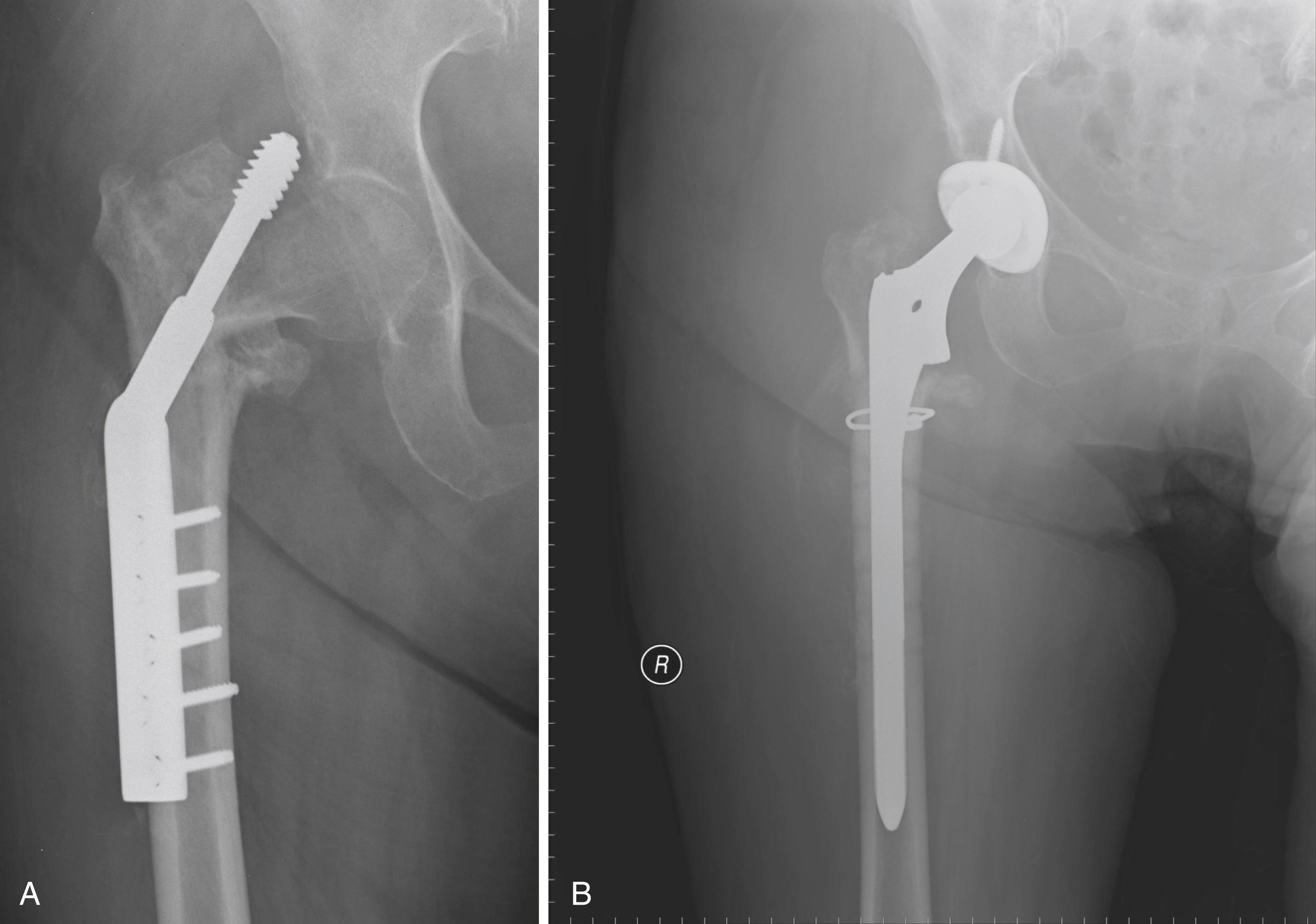
With nonunion of a femoral neck fracture, a portion of the femoral neck may be eroded but reconstruction usually can be accomplished easily using a standard femoral component with a long neck. In contrast, with trochanteric nonunions, the length of the femur generally cannot be restored with a standard implant, and a calcar replacement stem often is required (see Fig. 3.25C ). Because a calcar replacement stem simplifies the operation, allows early weight bearing, and obviates the need for union at a graft-host junction, it is preferable to bone grafting.
Plates and screws in the proximal femur may be covered with bone and difficult to remove. Removal of broken screws may leave a large defect in the femoral cortex that can give rise to fracture. In these cases, a longer stem is required to bypass screw holes by approximately two bone diameters ( Fig. 3.95 ). Cortical bone beneath a femoral side plate may become markedly porotic and easily perforated by reamers and broaches. We have used cortical strut grafts over the site of the plate in these cases for protection from fracture ( Fig. 3.96 ). When a cemented stem is used, an attempt should be made to occlude femoral screw holes during cementation. Still, the cement mantle quality is typically inferior compared with intact femurs. Additionally, with previously unstable trochanteric fractures, malunion with medial displacement at the fracture site may produce distortion of the proximal femur and make preparation of the femur more hazardous. When a cephalomedullary nail has been used for fracture fixation, the endosteal surface becomes sclerotic and cement interdigitation is less reliable. We prefer cementless femoral fixation in these cases also ( Fig. 3.97 ). Prior intramedullary nail placement also leaves a variably sized defect in the abductor mechanism and may have produced fragmentation of the greater trochanter, requiring fixation.
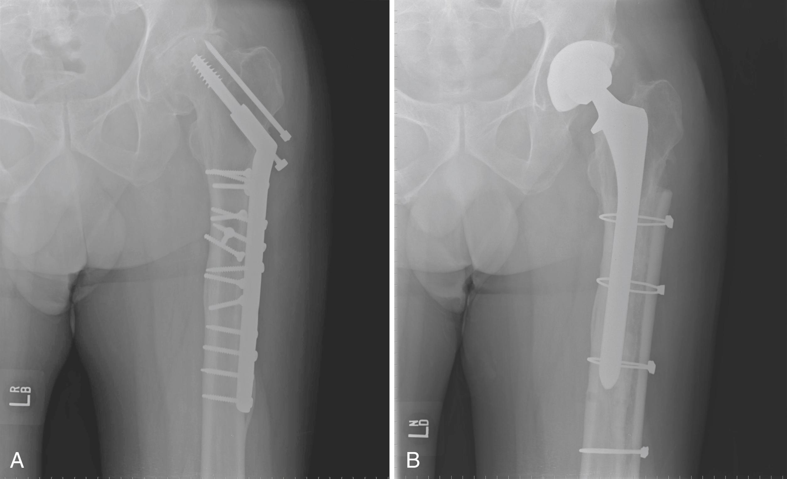
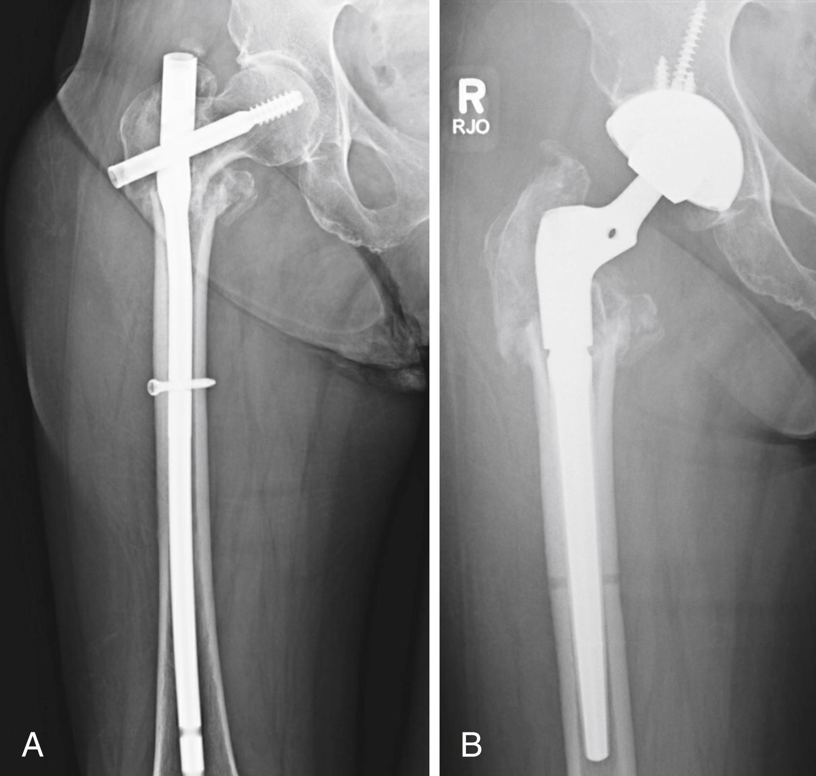
Hospitalization and subsequent rehabilitation of patients with THA for sequelae of failed fixation of a hip fracture are more prolonged than for similar patients with arthroplasty for arthritic conditions. Many patients with hip fractures have been nonambulatory for a period after the initial fracture and become very debilitated. Complications are more common, and the overall mortality is higher than for patients who undergo THA for arthritic conditions. Archibeck et al. reported an early complication rate of 11.8% including dislocations and periprosthetic fractures. Conversion surgery from prior intertrochanteric fracture fixation is associated with higher complication rates and worse outcomes than for prior femoral neck fractures. Haidukewych and Berry reported a series of 60 patients with prior intertrochanteric fracture fixation. Surgical time was prolonged with blood loss of more than 1000 mL. Medical complications arose in 20% and survival was 87.5% at 10 years. In a series of 59 cases, Morice et al. reported an intraoperative femoral fracture in 17% and dislocation in 6.8%. There were significantly more intraoperative fractures and medical complications in those with prior intertrochanteric fractures. Pui et al. also reported a multi-institutional series of 60 patients comparing conversion from cephalomedullary devices and sliding hip screws. The complication rate in converted nail patients was significantly higher, at 41.9% versus 11.7% with sideplate devices. In contrast, Hernandez reported a series of 62 patients converted from in situ fixation of intracapsular femoral neck fractures. There was a low rate of complications, and survival free of any reoperation was 97% at 5 years.
Fractures of the acetabulum with or without dislocation of the hip, although they can become painful later, usually are treated initially by open reduction and internal fixation. A united fracture provides better bone for support of the acetabular component if arthroplasty should become necessary. Occasionally, primary arthroplasty is indicated in an older osteoporotic patient who has an acetabular fracture combined with an unreconstructable fracture of the femoral head or neck, marked articular surface impaction or comminution, or a previously arthritic joint ( Fig. 3.98 ). Both the fracture reduction and arthroplasty can be carried out though a single approach. Mears and Shirahama reported a technique of acetabular fracture fixation with braided cables combined with acute THA. Fracture union occurred in 19 patients, and there were no loose implants. In a larger series of elderly patients with acute acetabular fractures treated with arthroplasty, Mears and Velyvis found good or excellent outcomes in 79% of cases. Small degrees of acetabular component migration occurred within the first 6 weeks, but no acetabular component had evidence of late radiographic loosening. Weaver et al. reported a series of elderly patients treated with either open reduction internal fixation ( ORIF) or acute hip arthroplasty. Those treated with ORIF had a 30% rate of reoperation compared to 14% in the arthroplasty group. Pain scores were also better in the arthroplasty group.
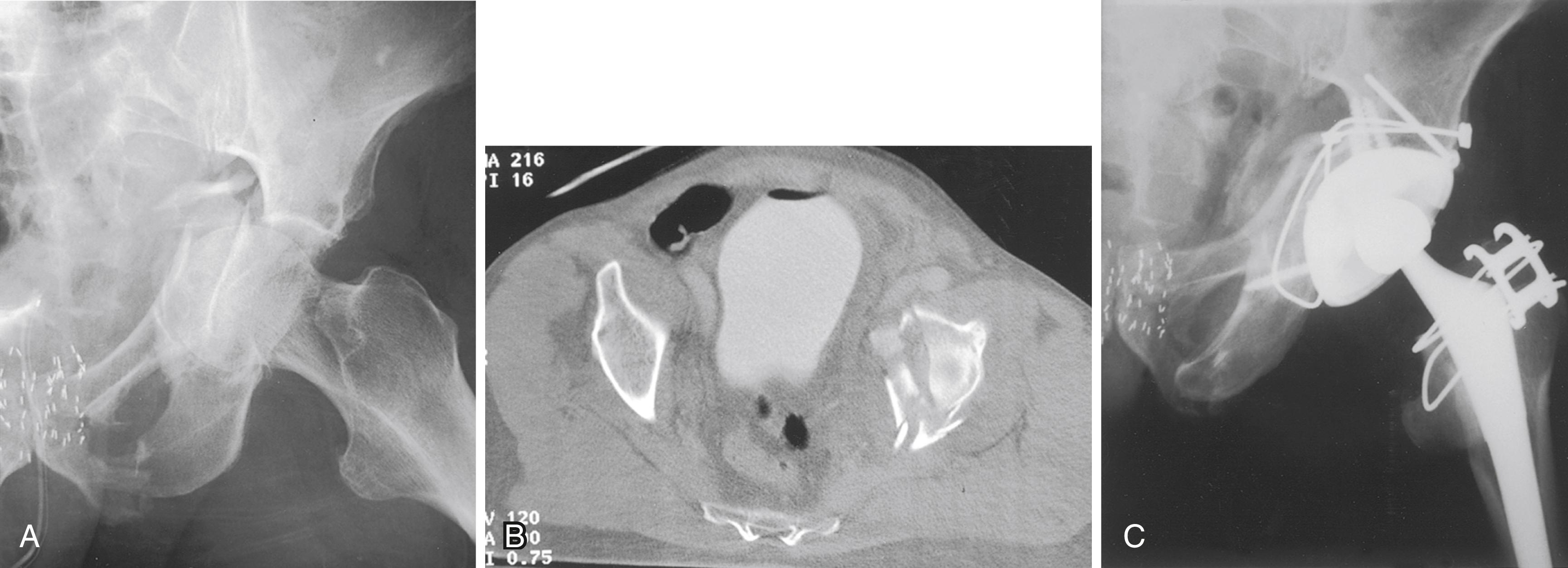
High rates of blood transfusion and prolonged operative times have been reported in several series. Chakravarty et al. described a technique of percutaneous column fixation combined with THA to reduce operative time and blood loss associated with traditional acetabular fracture fixation techniques. This procedure is best accomplished with collaboration of surgeons familiar with techniques of open reduction of acetabular fractures and of complex hip arthroplasty.
In old fractures of the acetabulum treated nonoperatively, residual pelvic deformity and areas of nonunion are common. A significant bony defect may be present posteriorly, especially if there has been a previous fracture of the posterior wall. Judet views (see Chapter 56 ) of the acetabulum and a CT scan show the extent of the defect and detect areas of nonunion not identified on plain radiographs. Failure to recognize these posterior deficiencies often leads to placement of the acetabular component in retroversion, with subsequent dislocation. At the time of arthroplasty, either the acetabulum must be deepened so that the posterior edge of the cup is supported by bone or the posterior wall must be extended by a graft consisting of part of the excised femoral head and neck or an allograft anchored with several screws or a buttress plate. For smaller contained defects, morselized autograft from the femoral head is adequate. In patients with nonunion of a displaced transverse acetabular fracture or patients with extremely irregularly shaped defects, an antiprotrusio cage may be used along with a hemispherical acetabular component (cup-cage construct).
If open reduction of the acetabulum has been done previously, extensive soft-tissue scarring can be expected and exposure may be difficult. Heterotopic ossification complicates exposure further and can cause impingement after the components are placed. Excision of heterotopic bone is laborious and increases operative time and blood loss. Efforts to prevent recurrence of heterotopic bone are warranted (see section on heterotopic ossification).
Previously placed internal fixation devices can be exposed during the process of reaming the acetabulum, and it may be necessary to remove them to implant the acetabular component properly. Considerable additional exposure may be required to remove screws and plates, risking injury to the sciatic nerve within scarred soft tissues. The ready availability of metal-cutting tools and screw removal instruments facilitates extraction of previously placed implants from the interior of the acetabulum without added extraarticular exposure. The acetabular component often can be implanted with removal of only a portion of the hardware, leaving the remainder undisturbed.
Makridis et al. conducted a meta-analysis of published series of total hip replacement in patients with acetabular fractures. Heterotopic ossification, infection, dislocation, and nerve injuries were the most commonly reported complications. Acetabular component survival was only 76% at 10 years. Yuan, Lewallen, and Hanssen reported no aseptic loosening with a highly porous metal acetabular component (see Fig. 3.31 ), but failures related to infection were reported. In a case-control study of patients undergoing hip arthroplasty after prior acetabular fracture compared to those with osteoarthritis or avascular necrosis, Morison et al. found the prior fracture patients had a markedly inferior 10-year survivorship and higher rates of infection, dislocation, and heterotopic ossification.
Several problems may be encountered in inserting the femoral stem for arthroplasty after proximal femoral osteotomy or when the proximal femur is otherwise deformed. Anatomic distortion and scarring from previous surgery make the surgical exposure more hazardous. The displacement of the fragments and the dense, cancellous bone in the femoral canal at the level of the healed osteotomy require careful reaming to broach the obstruction and to avoid cortical perforation or fracture. A high-speed burr may be required to remove dense intramedullary bone. Implant malposition and bony impingement resulting from the distorted femoral architecture can lead to hip instability. Previously placed internal fixation devices often are covered with bone, and their removal alone constitutes a significant operation. Broken screws are common, and the femur is prone to fracture after their removal. The femoral cement-bone interface often is imperfect when there are multiple cortical perforations, and the durability of fixation is compromised. If removal of implants is complex, a staged procedure is appropriate, with the arthroplasty being done after the soft tissues and any femoral cortical defects have healed.
Deformity may be present either in the proximal metaphyseal area or distally in the diaphysis. The location, type, and degree of deformity are important factors in preoperative planning. A metaphyseal valgus deformity produces a femur with a straight medial border, and conventional metaphyseal-filling cementless implants are unsuitable. We have used modular stems ( Fig. 3.99 ) effectively in this situation (also see Fig. 3.23 ). Alternatively, the deformed neck segment may be resected and replaced with a calcar-replacement type of stem (see Fig. 3.25C ). When there has been a previous metaphyseal varus osteotomy, conventional implants generally can be used, although overhang of the greater trochanter may require trochanteric osteotomy to avoid fracture or varus stem alignment. Metaphyseal rotational deformities usually can be managed by cementing a slightly smaller stem in the proper rotational alignment or by use of a cementless stem with diaphyseal fixation alone. Repeat osteotomy at the metaphyseal level should be avoided because the proximal fragment would be small, and it would be difficult to achieve stability at the osteotomy site. The application of supplemental plates and strut grafts to the metaphysis often is technically unsatisfactory, and the added bulk increases the risk of bony impingement and dislocation. If repeat osteotomy is required to manage a metaphyseal deformity, it generally should be done at the subtrochanteric level where fixation is more reliable.
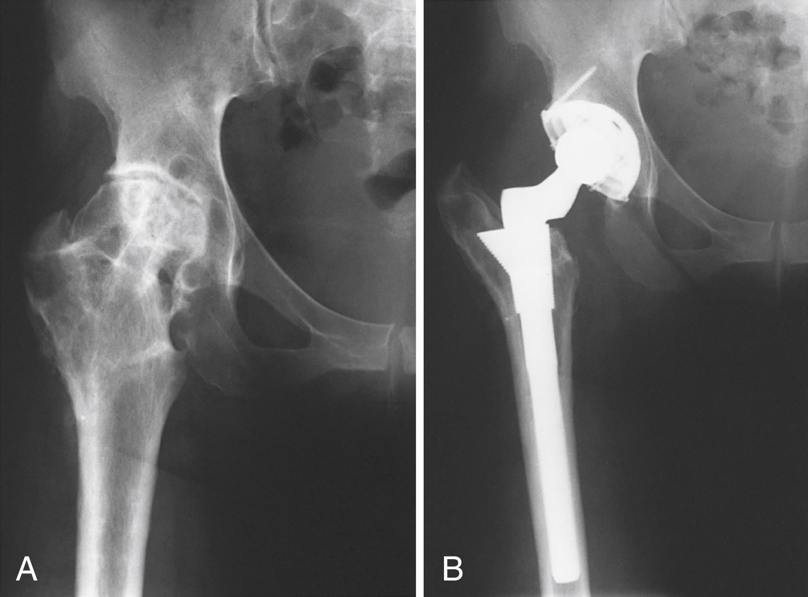
Diaphyseal deformities generally have a more substantial effect on implant placement. For deformities in the distal part of the diaphysis, a short stem can be used and the deformity need not be directly treated. If the deformity is in the subtrochanteric area, however, careful preoperative planning is mandated. Minor angular and translational deformities usually can be negotiated with a cemented stem of a size smaller than usual to preserve an adequate circumferential cement mantle. If angular deformity is significant, however, or translation of greater than 50% is present, repeat osteotomy is needed ( Fig. 3.100 ). Surgery can be done in two stages, although the introduction of cementless stems has simplified the operation and made union predictable with a single-stage procedure. Osteotomy also provides direct access to dense intramedullary bone at the previous surgical site, simplifying its removal. Stable fixation must be obtained at the osteotomy site for union to occur. A fluted or extensively porous-coated stem is needed to achieve distal fixation, and a precise fit in both fragments must be obtained to provide rotational stability. If this cannot be achieved with the stem alone, a cortical strut or a plate must be added. An oblique or step-cut osteotomy is intrinsically more stable than a transverse one, although the procedure is more challenging from a technical standpoint. This is particularly true if there is rotational malalignment that must be corrected. Cement can be used for stem fixation, but the cement inevitably extrudes into the osteotomy site and jeopardizes union. For this reason, we prefer cementless femoral components when a femoral osteotomy is necessary. Mortazavi et al. reported a series of 58 patients with proximal femoral deformity who had hip arthroplasty. Nonprimary femoral components were used in 25%, and 23% required femoral osteotomy. Cementless fixation provided reliable fixation in this technically challenging situation.
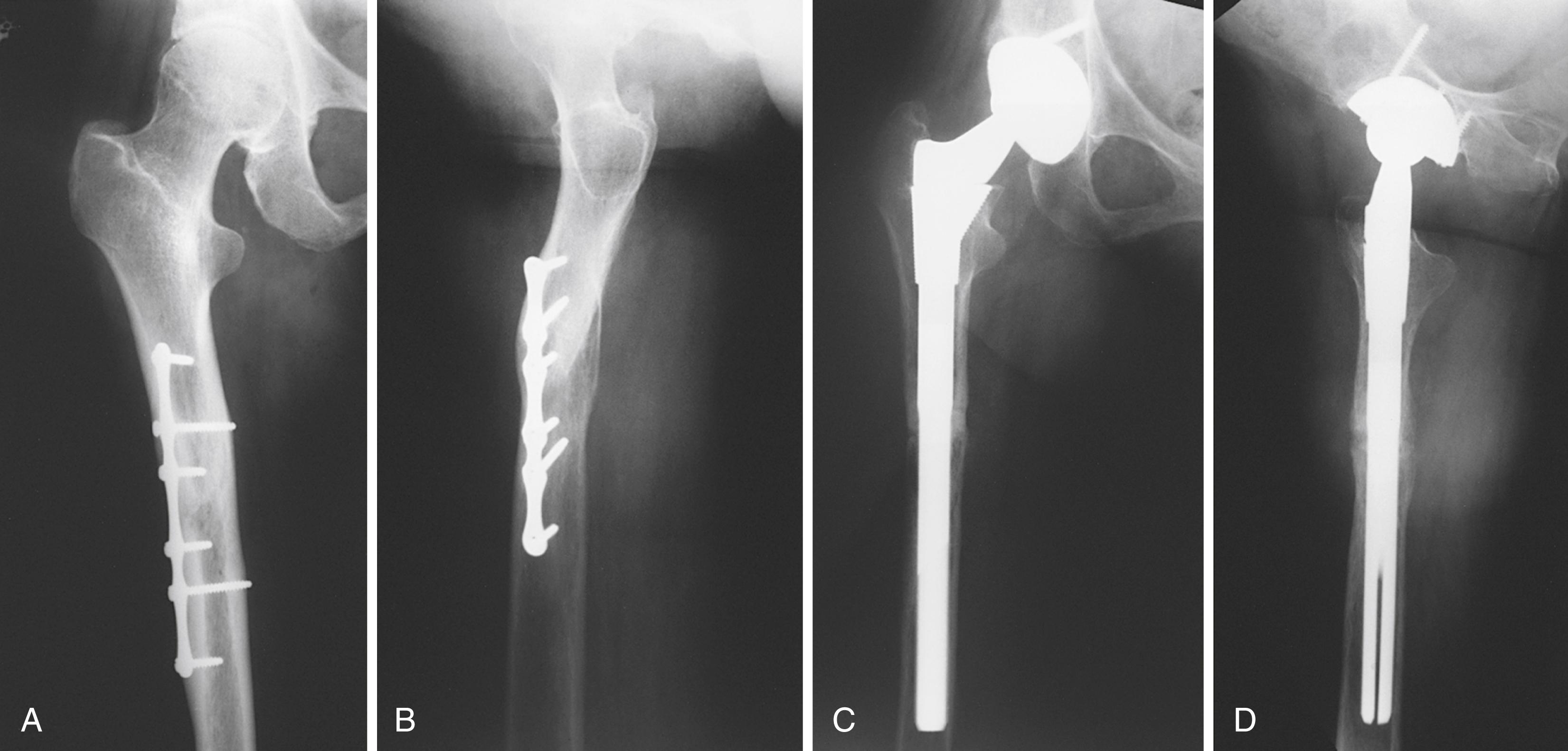
With a resurgence of interest in pelvic and periacetabular osteotomy, the need for later hip arthroplasty in these patients is likely to become more common. Parvizi, Burmeister, and Ganz reported results in 41 patients undergoing total hip procedures after prior periacetabular osteotomy. Because the initial osteotomies were performed through a Smith-Petersen approach, the procedures were done through virgin lateral soft tissues. There were no acetabular column defects, but retroversion of the acetabulum was a common finding. The prior osteotomy was not thought to compromise the results of the arthroplasty. Shigemura et al. conducted a meta-analysis of hip arthroplasties following pelvic osteotomy. They found less cup anteversion, but no difference in cup abduction, operative time, or blood loss between cases with or without prior pelvic osteotomy. Therefore, careful attention is needed when positioning the acetabular component. In a series of patients with prior Chiari osteotomy, Hashemi-Nejad et al. found less acetabular augmentation was needed compared with dysplastic hips without prior osteotomy.
With widespread media attention to the success of hip replacement, patients often are unwilling to accept arthrodesis as a primary treatment option and likewise request conversion of an existing arthrodesis to restore motion. The effects of hip fusion on other joints are significant. Often the ipsilateral knee is limited in motion, with a variable degree of ligamentous laxity, and has a tendency for valgus malalignment. Pain caused by arthritis or other conditions of the lumbar spine can increase significantly when sitting with the spine partially flexed because of a fused hip. Care must be taken, however, to determine whether back and leg pain may be caused by a herniated lumbar disc or some other condition that may not be improved by THA. If the hip is fused in poor position (i.e., flexed >30 degrees, adducted >10 degrees, or abducted to any extent), osteotomy to correct the position may be considered, especially in younger patients. Arthrodesis of one hip also applies greater mechanical stress to the opposite hip. THA may be indicated if a fused hip causes severe, persistent low back pain or pain in the ipsilateral knee or contralateral hip or if a pseudarthrosis after an unsuccessful fusion is sufficiently painful ( Fig. 3.101 ).
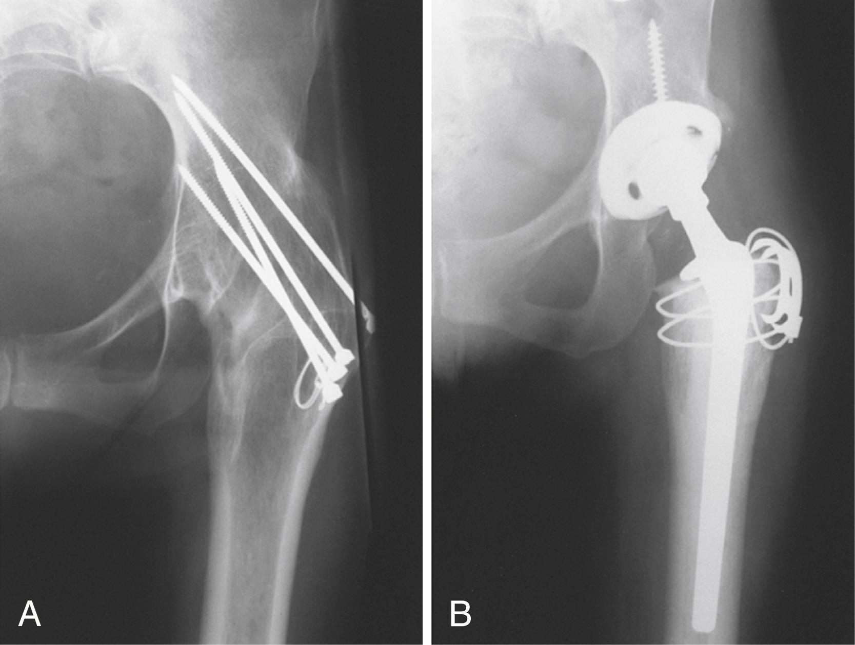
The history of the initial reason for the arthrodesis is important. Patients with prior infection require a thorough evaluation to rule out persistence. A careful assessment of the function of other joints, especially the lumbar spine, should be done, and leg-length discrepancy should be measured. Preoperative metal-subtraction CT can be helpful in determining the adequacy of bone stock and the presence of a pseudarthrosis.
Function of the abductors is difficult to evaluate before surgery, but in some patients active contraction of these muscles can be palpated. Examination of the hip with the knee flexed helps differentiate the TFL from the abductor muscles. If the hip has been fused since childhood, and the trochanter appears relatively normal, the abductor muscles are probably adequate. If the bone around the hip has been grossly distorted by disease or by one or more fusion operations, the abductor muscles may be inadequate. The utility of electromyographic testing of abductor function or imaging modalities such as MRI has not been established. Weak abductor musculature is associated with poorer functional outcome.
At surgery, a variety of screwdrivers, metal cutters, and other extraction instruments should be available to remove antiquated fixation devices. The conversion of a fused hip to a THA is safer and easier if the trochanter is osteotomized. Complete mobilization of the femur without trochanteric osteotomy is difficult, and the resulting inadequate exposure predisposes to component malposition, errors in femoral reaming, and fractures. In addition, the limb often is fixed in external rotation, and consequently the trochanter is posterior, overhanging the hip joint. Osteotomy of the neck can be difficult through a posterior approach unless the trochanter is osteotomized. The sciatic nerve often is displaced closer to the hip because the head-neck length is shorter than normal and the nerve may be fixed in scar tissue; for this reason, special care is taken to avoid damage to the nerve. Careful monitoring of tension on the nerve is necessary, and neurolysis may be indicated if the extremity is significantly lengthened.
After the femoral neck has been exposed, it is divided with a saw. The location of the osteotomy is determined from bony landmarks or the position of previous fixation devices. The neck should not be divided flush with the side of the ilium because sufficient bone must be left to cover the superior edge of the cup ( Fig. 3.102 ). After the neck has been divided, release of the psoas tendon, gluteus maximus insertion, and capsulotomy are necessary to mobilize the proximal femur.
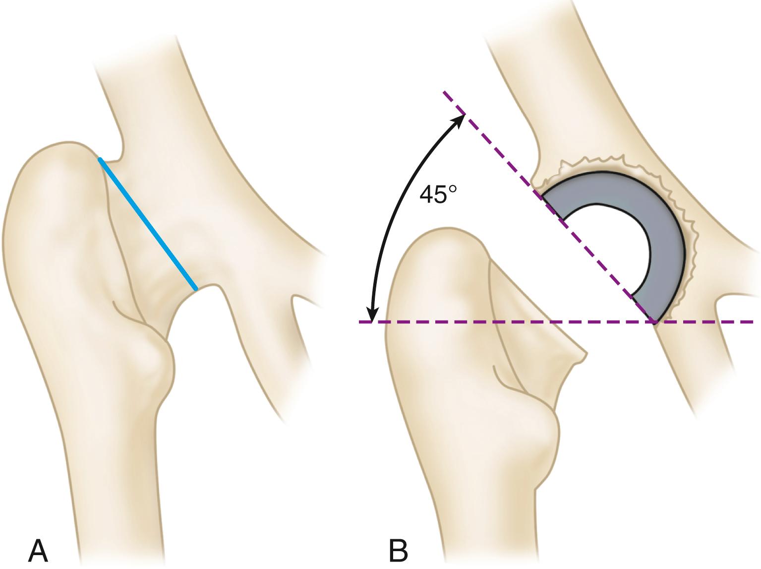
Usually the pelvic bone is sufficiently thick to cover the cup adequately if the site for acetabular preparation is chosen carefully. Distortion of the normal bony architecture may cause difficulty in locating the appropriate site for acetabular placement. Usually the anterior inferior iliac spine (AIIS) remains intact and serves as a landmark. Additionally, a retractor can be placed in the obturator foramen. Acetabular preparation is performed with conventional reamers, centering within the available bone to preserve the anterior and posterior columns. Intraoperative fluoroscopy or radiograph is helpful early in the acetabular preparation to ensure that the position of the reamer is as expected.
The femoral canal is prepared in the usual manner, taking into account any deformity from prior disease or femoral osteotomy. Trochanteric fixation is accomplished by standard techniques (see Figs. 3.74 to 3.76 ). If the abductors are markedly atrophic or deficient, a constrained (see Fig. 3.34 ) or dual mobility (see Fig. 3.35 ) acetabular component should be considered.
After the procedure has been completed, the patient is placed supine. If the hip cannot be abducted 15 degrees because the adductors are tight, a percutaneous adductor tenotomy is done through a separate small medial thigh incision. The extremity usually is lengthened by the procedure and corrects prior flexion deformity. Lengthening usually is desirable because in most instances the limb has been shortened by the original disease, by the procedure for fusing the hip, or by the flexion deformity.
The postoperative treatment is routine, but the hip should be protected for at least 3 months by use of crutches and then by use of a cane while the hip abductors and flexors are being rehabilitated. Patients rarely regain flexion to 90 degrees, but they achieve sufficient motion to relieve back symptoms and permit sitting and walking and tying shoes. Walking ability usually is improved, but in patients with inadequate abductor function the gait pattern may worsen, and the support of a cane or walker may be required even if the patient did not use one before conversion to arthroplasty. Most patients have some degree of residual abductor weakness and limp, although this tends to improve over several years.
The complication rate for conversion of an arthrodesis to an arthroplasty is high. In the Mayo Clinic series of Strathy and Fitzgerald, 33% of patients experienced failure within 10 years because of loosening, infection, or recurrent dislocation. Patients with a spontaneous ankylosis fared much better than patients who had a prior surgical arthrodesis. Jauregui et al. conducted a meta-analysis of 1104 hip fusion conversions and reported 5.3% had infection, 2.6% developed instability, 6.2% had loosening, 4.7% with nerve complications, and 13.1% experienced abductor-related complications. Celiktas et al. reported a series of 28 patients operated through a posterior approach without trochanteric osteotomy. Although their procedures were technically feasible, five patients had intraoperative trochanteric fracture.
Patients with Paget disease may have degenerative arthritis in one or both hips, varying degrees of protrusio acetabuli, varus deformity of the neck and proximal femur, and anterolateral bowing of the shaft ( Fig. 3.103 ). In addition, incomplete (stress) fractures may develop on the convex side of the femoral shaft. These fractures, the metabolic disease alone, secondary sarcoma formation, and radicular problems referable to the lumbar spine all can cause hip pain, in addition to the hip arthritis, and it may be difficult to differentiate the sources of pain. Preoperative medical management with bisphosphonates and calcitonin can help control pain and decrease perioperative blood loss. If the disease is active, the administration of calcitonin before and after surgery is advisable to decrease the osteoclastic activity and possibly to reduce the risk of loosening as a result of postoperative bone resorption.
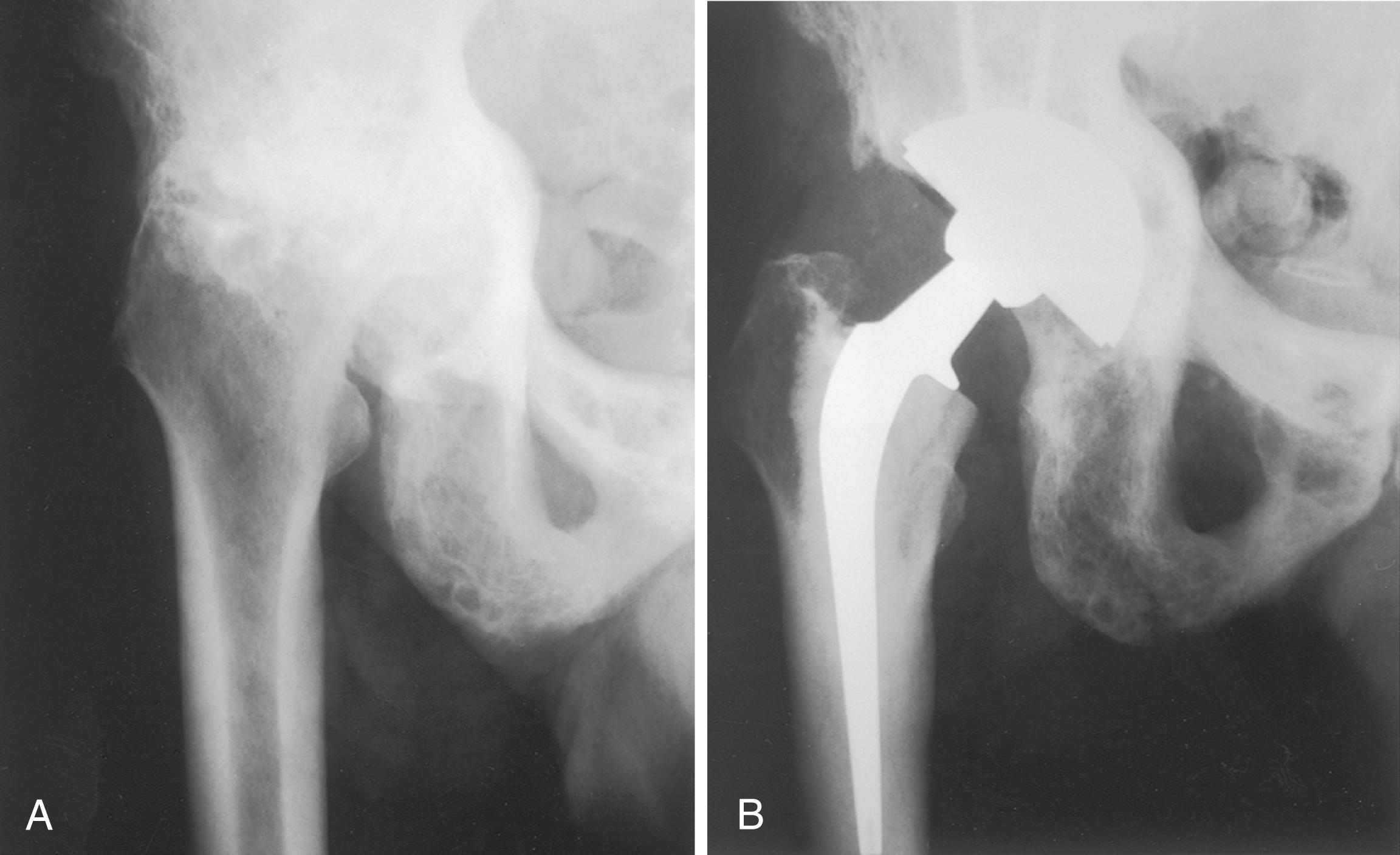
The deformed proximal femoral bone may be osteoporotic or markedly dense, and these changes can cause technical difficulties. Consequently, anteroposterior and lateral radiographs of the hip and femoral shaft should be evaluated carefully before surgery to determine the extent of bowing and the presence of lytic or dense lesions. Usually the anterolateral bowing is not a problem in reaming the canal or positioning the stem because the medullary canal is wide. If the deformity is considerable, however, a femoral osteotomy may be needed for stem placement. The presence of dense intramedullary bone can make identification and opening of the canal difficult. A high-speed burr and intraoperative use of fluoroscopy are helpful when this is recognized on preoperative radiographs.
Bleeding can be excessive, especially in patients with osteoporotic bone. The lack of a dry bone bed can reduce cement interdigitation in the femur and the acetabulum and compromise fixation. Conversely, cementless fixation has proven durable despite concerns that altered bone morphology may prevent osseointegration.
The results of THA for painful arthritis and for displaced femoral neck fractures in Paget disease are encouraging, with a reported 7- to 10-year survival rate of 86%. The results of internal fixation of these fractures and of endoprostheses for fractures or arthritis in this disease have been unsatisfactory. THA has become the procedure of choice. Heterotopic bone formation has been reported as a common postoperative complication, and prophylactic measures to reduce its formation seem warranted.
Patients with the chronic nonneuropathic form of Gaucher disease may have osteonecrosis of the femoral head bilaterally, and if it is sufficiently painful, they may require a THA. Osteonecrosis of the femoral head may produce the first symptoms that suggest the diagnosis of Gaucher disease. The disease is characterized, however, by osteopenia, with areas in which the trabeculae have a moth-eaten appearance and patchy areas of sclerosis; much of the bone marrow may be replaced by Gaucher cells. Because the medullary canal usually is wide, implant fixation even with cement is difficult, and the femur can be fractured easily. The disease often is characterized by recurring, nonspecific bone pain, making evaluation of some postoperative symptoms difficult. Anemia and thrombocytopenia may complicate surgical interventions. Many patients have required splenectomy, and infections are a common complication of Gaucher disease. Other complications include excessive intraoperative and postoperative hemorrhage and a high incidence of loosening because of the continued Gaucher cell proliferation and erosion of bone. Enzyme replacement therapy may ameliorate the osseous problems associated with the disease.
Patients with sickle cell anemia and sickle cell trait may develop painful osteonecrosis of the femoral head. The process can be bilateral. Radiographs may reveal a large collapsed avascular area or an arthritic process caused by small focal areas of osteonecrosis near the articular surface.
In the past, the life expectancy of patients with the SS form of sickle cell anemia was thought to be short (approximately 30 years), but with improvements in medical management and antibiotics, they may live much longer. Although patients with sickle cell trait also develop osteonecrosis, they do so less often than patients with sickle cell disease. Many more patients have the trait than the disease, however.
Patients with sickle cell anemia may require transfusions before surgery, and transfusion reactions owing to alloimmunization are more frequent. Many patients are chronically dependent on narcotic analgesics, and epidural anesthesia and multimodal pain management techniques are advisable. Cardiopulmonary care must be aggressively managed, and perioperative hypoxia, acidosis, and dehydration must be avoided. A multidisciplinary approach to the medical management of sickle cell patients reduces morbidity.
Acetabular bone quality may be poor and a variable degree of protrusio deformity may be present, making hip dislocation more difficult. Bone grafting of acetabular defects may be required (see section on protrusio acetabuli). Areas of femoral intramedullary sclerosis from prior infarction may be manifest as “femur within femur” on preoperative radiographs. In our experience, this problem is underestimated by preoperative radiographs, and at surgery the canal may be completely obstructed by very dense bone. Major technical problems in reaming the canal must be anticipated, and the risk of femoral fracture and cortical perforation is high. Use of fluoroscopy is helpful for centering instruments in the femoral canal, and reaming over a guidewire is inherently safer. Preliminary removal of sclerotic bone with a high-speed burr also makes broaching easier.
Although these patients are more susceptible to Salmonella infections, the literature does not support this as being a pathogen in postoperative sepsis of hip arthroplasty. Specific prophylaxis for Salmonella does not seem to be warranted. Because of functional asplenia, patients with sickle cell anemia are prone to developing hematogenous infection of the hip after surgery. Aggressive antibiotic management is indicated when the possibility of hematogenous infection exists. The ESR is of no value in determining whether a patient with sickle cell disease has an inflammatory process. Pain resulting from a sickle cell crisis caused by vascular occlusion often presents a problem in determining whether a particular pain is caused by infection.
Complications such as excessive bleeding, hematoma formation, and wound drainage are common after arthroplasty in patients with sickle cell disease; complications have been reported in nearly 50% of THAs in sickle cell patients. Because no other option yields consistently superior results, the procedure is still justified in patients with severe pain and disability. Patients should be advised, however, of the increased risk of complications imposed by their disease. Recent series using cementless fixation have been somewhat more encouraging. Ilyas et al. reported 10-year survivorship of 98% using cementless femoral and acetabular components, with deep infection in 6.77%.
Osteoporosis, osteonecrosis, and femoral neck fracture are common sequelae of chronic renal failure. With the institution of hemodialysis and the success of renal transplantation, an increasing number of these patients are becoming candidates for hip arthroplasty. Poor wound healing, infection, and an array of general medical complications related to the disease process can be anticipated. Sakalkale, Hozack, and Rothman reported THA in 12 patients on long-term hemodialysis. There was an early complication rate of 58%, and infection developed in 13%. Longevity was limited after surgery, and the authors recommended limiting the procedure to patients with a longer life expectancy. Lieberman et al. reported their results after THA in 30 patients who had renal transplants and 16 who were being treated with hemodialysis. Patients with transplants had postoperative courses similar to other patients with osteonecrosis, whereas in the patients who were being treated with hemodialysis 81% had poor results and 19% developed infection. These authors recommended limiting hip arthroplasty to patients who are expecting renal transplant or who have already had successful transplantation. In contrast, a series from the Mayo Clinic found a higher cumulative revision rate in transplant patients, with complications in 61%. A high rate of loosening of cemented femoral components was noted. More encouraging results have been reported with cementless, extensively porous-coated implants. Nagoya found predictable bone ingrowth with no infections in 11 patients on long-term hemodialysis with average follow-up of more than 8 years.
Hemophilic arthropathy involves the hip joint far less often than the knee and elbow. Consequently, there is a paucity of information specific to hip arthroplasty. When hip involvement develops before skeletal maturity, valgus deformity of the femoral neck, flattening of the femoral head, and a variable degree of acetabular dysplasia are present. The radiographic appearance is similar to that of LCPD.
A multidisciplinary approach is essential for surgical treatment of hemophilic arthropathy. Ready access to a well-managed blood bank and an experienced hematology staff are requisites; for this reason, arthroplasty in hemophilic patients generally is done only in specialized centers. Patients with circulating antibodies to clotting factor replacements (inhibitors) are not considered suitable candidates for surgery because of the risk of uncontrollable hemorrhage. In a study of the Nationwide Inpatient Sample, Kapadia et al. reported transfusions in 15.06% of hemophiliacs compared to 9.84% in matched controls following lower extremity arthroplasty.
Complications occur frequently in these patients. In a multicenter study, Kelley et al. reported that 65% of cemented acetabular components and 44% of cemented femoral components had radiographic evidence of failure at a mean follow-up of 8 years. Nelson et al. found similar failure rates in a long-term study of patients from a single center. Results have been better with modern cementless implants. Carulli et al. reported no failures or complications at mean follow-up of 8.1 years in 23 patients with a mean age of 40.6 years.
Late hematogenous infection may be a significant problem, and the risk increases if patients previously exposed to HIV through factor replacements develop clinical manifestations of acquired immunodeficiency syndrome. Enayatollahi et al. reported infection in 10.98% of patients with both HIV and hemophilia versus 2.28% in patients with HIV only.
Most patients with a history of pyogenic arthritis of the hip who are considered candidates for THA had the hip joint infection in childhood and had either a spontaneous or surgical hip fusion or developed a pseudarthrosis of the hip. Pyogenic arthritis of the hip in adults is rare except after internal fixation of fractures.
Arthroplasty may be considered in an adult whose hip was fused by a childhood pyogenic infection and in whom inflammation has not been evident for many years. A solid fusion with a uniform trabecular pattern crossing the joint usually indicates the absence of residual infection. Focal areas of decreased density and some sclerosis and irregularity of the trabeculae crossing the joint line may signify a residual focus of infection, however. Tang et al. found MRI to be 100% sensitive in showing the presence of active infection in patients with prior osteomyelitis. Determination of ESR and CRP levels, hip joint aspiration, bone biopsy, and radionuclide scanning all may play a role in the preoperative evaluation. Intraoperative frozen sections of periarticular tissues also should be obtained. When any of these studies points to residual infection around the hip, a two-stage procedure is appropriate.
Often the limb is shortened as a result of partial destruction of the femoral head and neck and the acetabulum. The flexed and adducted position of the hip adds to the apparent shortening. The femur may be hypoplastic with anteversion of the femoral neck and variable degrees of resorption of the femoral head. Deep scarring may be present as a result of multiple incision and drainage procedures and sinuses around the hip. If present, previous incisions should be used, and prior sinus tracks should be completely excised. Lack of subcutaneous tissues over the trochanter and in the area of the proposed incision may require rotation of a skin flap before the THA.
In a group of 44 patients who underwent THA after pyogenic arthritis in childhood, Kim found no reactivations of infection despite the use of acetabular allografts in 60% of the patients. Perioperative femoral fracture was common because many of these patients had a small, deformed proximal femur. In a larger series of 170 patients from the same institution, there were no recurrent infections when the period of quiescence had been at least 10 years. Operative difficulties were frequent, however, and polyethylene wear and implant loosening were common late complications. Similarly, Park et al. reported that poor results in this population were attributed to anatomic abnormalities that had developed as a result of infection rather than recurrence of infection following arthroplasty.
The hip is the second most common site of osseous involvement of tuberculosis following the spine, resulting in severe cartilage and bone destruction, limb shortening, and instability. The diagnosis should be considered in patients who come from a country in which the disease is prevalent, in patients with a history of having been in a spica cast as a child, in patients being treated for acquired immunodeficiency syndrome, and in patients with undiagnosed arthritis of the hip. Tuberculous bacilli are fewer in number in bone infections than in infected sputum, making the diagnosis of tuberculous osteomyelitis difficult.
A longer period of chemotherapy has been recommended when hip arthroplasty is performed in the presence of active tuberculous arthritis. Mycobacterium tuberculosis has little biofilm and adheres poorly to implants. Many patients with reactivation of tuberculous infections after THA can be treated with debridement and drug therapy with retention of the prosthesis. Because of the emergence of drug-resistant strains of tuberculosis, preoperative tissue biopsy with culture and sensitivity are helpful in selecting the optimal chemotherapeutic agents.
Most patients are candidates for a single-stage procedure. In a systematic review of the available literature, Tiwari et al. identified 226 patients in whom antituberculosis treatment was administered for 2 weeks preoperatively and continued for 6 to 18 months following hip arthroplasty. Only three patients had reactivation of infection at mean follow-up of 5.48 years. The presence of a sinus track often is indicative of superinfection with S. aureus, and a two-stage procedure is indicated in these patients. Radical debridement of all infected tissue is required in either scenario. Both cemented and cementless fixation have been successful at mid-term follow-up.
Possible candidates for THA include patients with (1) metastatic tumors with a reasonable life expectancy, (2) some low-grade tumors, such as chondrosarcoma and giant cell tumor, and (3) benign destructive lesions, such as pigmented villonodular synovitis. For patients with primary lesions, curing the disease, and not restoration of function, should be the goal of surgery. Consequently, careful planning to determine the amount of tissue to be resected may require a bone scan, CT, and MRI. The surgical approach must be more extensive than usual to ensure complete excision of the tumor. A conventional THA may suffice, however, if only a limited amount of the acetabulum or the femoral head and neck must be resected to excise the tumor and a margin of normal tissue. If the greater trochanteric and subtrochanteric areas are resected, the hip may be unstable because reattaching the abductor muscles is difficult. An extra-long femoral component may be necessary because of other lesions more distal in the femoral shaft. A custom-made component or segmental replacement stem can be used (see Fig. 3.29 ); the gluteal muscles are sutured to holes made in the component for this purpose. An allograft-prosthesis composite with a long stem is an option in young patients. Cement fixation within the graft and a step-cut at the junction of the graft and host bone provide stability. The acetabulum can be reconstructed with cement, with additional support provided by a reinforcement ring or cage (see Fig. 3.36 ) or by threaded Steinmann pins inserted through the iliac wing into the acetabulum.
Patients with chronic neuromuscular disorders who come to hip arthroplasty usually have increased muscle tone or spasticity. Spasticity may be congenital, as with cerebral palsy, or acquired through brain or spinal cord injury. Acquired spasticity may be complicated by the presence of heterotopic ossification about the hip. Patients become candidates for THA because of fracture, end-stage hip arthritis, or painful subluxation. Although this group encompasses a broad range of congenital and acquired diseases and syndromes, certain management principles are applicable to all.
Patients with generalized neurologic problems are at greater risk for complications, and careful attention must be paid to care of the skin, pulmonary function, and urinary tract to prevent sepsis at these sites. Early mobilization, at least to a chair and preferably to weight-bearing status, prevents further muscular deterioration. Patients with retained motor function and intact cognition have better potential for recovery of mobility.
Combined flexion and adduction contractures are common, but their presence may not be appreciated when a patient has an acute fracture. This combination of deformities predisposes to postoperative dislocation, especially when surgery is performed through a posterior approach. A direct anterior or anterolateral approach may be preferable, although these approaches are less extensile when excision of heterotopic ossification is needed. Release of the anterior capsule and psoas and percutaneous adductor tenotomy all may be required. The degree of contractures usually is more severe in patients with congenital neurologic disorders. Placement of the acetabular component in additional anteversion also makes the hip more stable. If the stability of the hip during surgery is unsatisfactory, or if the patient’s muscular control of the hip is insufficient to maintain appropriate postoperative precautions, a hip spica cast probably should be worn for 4 to 6 weeks until the soft tissues have healed sufficiently to stabilize the joint. Occasionally, a constrained acetabular component may be necessary to prevent postoperative dislocation. Other tenotomies may be required to achieve knee extension and a plantigrade foot. In a series of 39 patients with cerebral palsy, Houdak et al. reported no difference in the rate of reoperation, survivorship, and complications compared to patients with osteoarthritis. Dislocations occurred in 7%.
Patients with paralytic conditions, such as the residuals of poliomyelitis, may develop hip arthritis in either the affected limb or a normal contralateral hip. Dysplasia may be present on the paralytic side, and overuse degenerative arthritic changes predominate on the nonparalytic side. Yoon et al. found that polio patients often had some residual pain after hip arthroplasty, possibly caused by muscular weakness inherent to the disease.
Medical and surgical complications can occur after THA and exert a significant effect on patient satisfaction and overall outcome of the procedure. Prevention of complications should be a consistent focus of all involved stakeholders. Prompt diagnosis and effective treatment are critical for a successful result.
According to a 2014 meta-analysis, the 30-day mortality rate was 0.3% for primary THA and the 90 day rate was 0.65%. Increased mortality rates were associated with advanced age, male gender, and medical comorbidities, particularly cardiovascular disease. Although careful preoperative medical evaluation is warranted in all patients, special attention should be directed to patients with these risk factors.
Careful preoperative screening should identify patients with known risk factors for excessive hemorrhage, including antiplatelet, antiinflammatory, or anticoagulant drug therapy; herbal medication use; blood dyscrasias and coagulopathies; and family or patient history of excessive bleeding with previous surgical procedures.
The most important surgical factor in preventing hematoma is careful hemostasis. Common sources of bleeding are (1) branches of the obturator vessels near the ligamentum teres, transverse acetabular ligament, and inferior acetabular osteophytes, (2) the first perforating branch of the profunda femoris deep to the gluteus maximus insertion, (3) branches of the femoral vessels near the anterior capsule, and (4) branches of the inferior and superior gluteal vessels. The iliac vessels are at risk from penetration of the medial wall of the acetabulum and removal of a medially displaced cup. Bleeding from a large vessel injury usually becomes apparent during the operation (see section on vascular injuries). Late bleeding (1 week postoperatively) may occur from a false aneurysm or from iliopsoas impingement ( Fig. 3.104 ). Arteriography may be required for identification of a false aneurysm along with possible embolization. Acetabular revision may likewise be necessary to correct iliopsoas impingement.
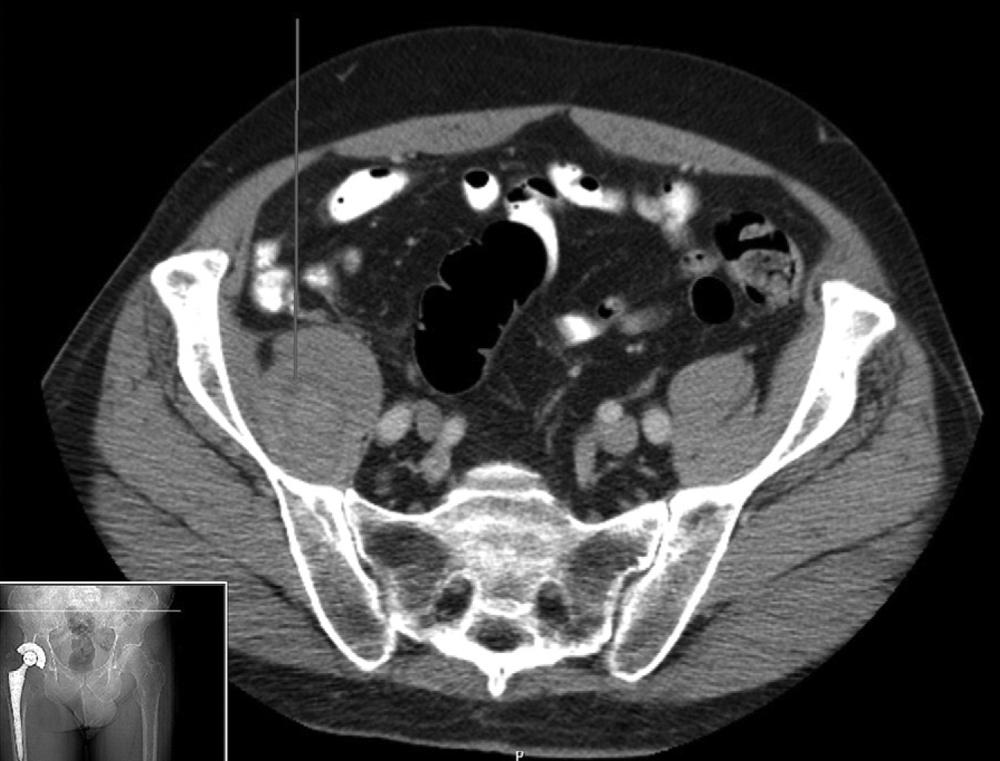
Excessive hemorrhage leading to hematoma formation uncommonly requires surgical intervention. Most patients can be managed by dressing changes, discontinuation of anticoagulants, treatment of coagulopathy, and close observation of the wound. Indications for surgical treatment of hematoma include wound dehiscence or marginal necrosis, associated nerve palsy, and infected hematoma. Evacuation of the hematoma and achievement of meticulous hemostasis should be accomplished in the operating room. The hematoma should be cultured to assess possible bacterial contamination, and antibiotics should be continued until these culture results become available. Debridement of necrotic tissue as needed and watertight closure also are required. Closed suction drainage seems warranted in this setting to avoid a recurrence.
Heterotopic ossification varies from a faint, indistinct density around the hip to complete bony ankylosis. Calcification can be seen radiographically by the third or fourth week; however, the bone does not mature fully for 1 to 2 years. The classification of Brooker et al. is useful in describing the extent of bone formation:
Grade I: islands of bone within soft tissues
Grade II: bone spurs from the proximal femur or pelvis with at least 1 cm between opposing bone surfaces
Grade III: bone spurs from the proximal femur or pelvis with less than 1 cm between opposing bone surfaces
Grade IV: ankylosis
Risk factors for heterotopic ossification include history of heterotopic ossification, diagnosis of hypertrophic osteoarthritis, ankylosing spondylitis, diffuse idiopathic skeletal hyperostosis (DISH), or Paget disease, male gender, and African-American ethnicity.
Surgical technique may play a role in the development of heterotopic ossification. Anterior and anterolateral approaches carry a higher risk of heterotopic ossification than transtrochanteric or posterior approaches.
Most who develop heterotopic ossification are asymptomatic; however, restricted range of motion and pain may occur in patients with more severe Brooker grade III or IV ossification. Routine prophylaxis against heterotopic ossification is not recommended for all patients but is warranted in high-risk groups.
Prophylaxis may include low-dose radiation and nonsteroidal antiinflammatory drugs (NSAIDs). Preoperative and postoperative radiation regimens with doses as low as 500 cGy have been successful. In a multicenter evaluation of radiation prophylaxis, failures occurred more commonly in patients treated more than 8 hours preoperatively or more than 72 hours postoperatively. Preoperative treatment should result in less patient discomfort than in the early postoperative period. Radiation exposure is limited to the soft tissues immediately around the hip joint, and ingrowth surfaces must be appropriately shielded ( Fig. 3.105 ).
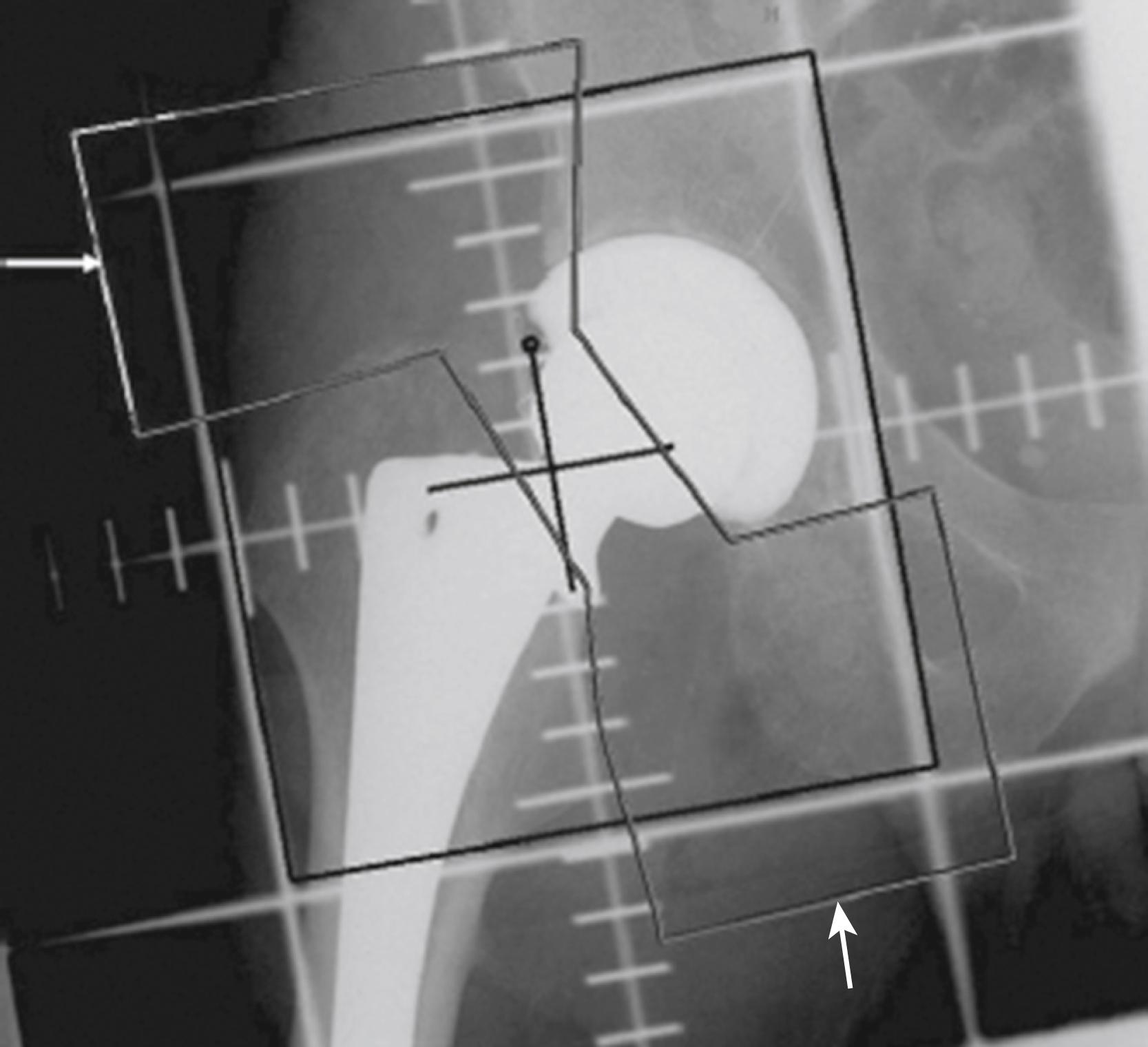
NSAIDs reduce the formation of heterotopic bone in many studies. Historically, nonselective cyclooxygenase-1 (COX-1) and cyclooxygenase-2 (COX-2) inhibitors for 6 weeks have been recommended, although courses of administration of 7 days are successful. Compliance is limited by medical contraindications to these drugs and patient intolerance. Multiple meta-analyses comparing COX-1 and COX-2 inhibitors showed no difference in efficacy in preventing heterotopic ossification. In light of a more favorable safety profile for the COX-2 inhibitors, they have been recommended for HO prophylaxis.
An operation to remove heterotopic bone is rarely indicated because associated pain usually is not severe and excision is difficult, requiring extensile exposure. The ectopic bone obscures normal landmarks and is not easily shelled out of the surrounding soft tissues. Substantial blood loss can be anticipated. Decreased technetium bone scan activity indicates that the heterotopic bone is mature, allowing for reliable excision. Radiation and NSAIDs have been used successfully to prevent recurrence. Range of motion should improve, but pain may persist.
Thromboembolic disease is one of the more common serious complications following THA. In early reports of hip arthroplasty without routine prophylaxis, venous thrombosis occurred in 50% of patients, and fatal pulmonary embolism occurred in 2% (Johnson et al.). More recently, a meta-analysis of studies including patients who were anti-coagulated prophylactically after surgeries between 1995 and 2015 found an estimated PE rate of 0.21%, which remained consistent across this time period.
Thromboembolism can occur in vessels in the pelvis, thigh, and calf. Of all thromboses, 80% to 90% occur in the operated limb. The temporal relationship of deep vein thrombosis (DVT) and PE to surgery is controversial. The peak prevalence of DVT varies among studies, with a range of 4 to 17 days after surgery reported. With shorter hospital stays, more thromboembolic events occur after discharge.
The best method of prophylaxis for thromboembolism is debatable. Currently, mechanical and pharmacologic modalities are used. For patients undergoing elective THA, the American College of Chest Physicians (ACCP) recommends one of the following anticoagulant agents: low molecular-weight heparin (LMWH), fondaparinux, apixaban, dabigatran, rivaroxaban, low-dose unfractionated heparin, adjusted-dose warfarin, aspirin, or intermittent pneumatic compression. For patients with high risk of bleeding, mechanical prophylaxis with intermittent pneumatic compression or no prophylaxis should be used. A minimum of 10 to 14 days of prophylaxis is preferred, with a period of up to 35 days also being suggested.
In 2011, the American Academy of Orthopaedic Surgeons (AAOS) published a revised clinical practice guideline regarding the prevention of venous thromboembolic disease after hip or knee arthroplasty. These recommendations stratify patients based on their risk of thromboembolism and major bleeding. Previous venous thromboembolism (VTE) is considered a risk factor for recurrence, whereas bleeding disorders or active liver disease are associated with increased risk for bleeding complications. After assessment of these risk factors, prophylactic measures are tailored accordingly. Patients who are not at increased risk for VTE or bleeding complications should receive pharmacologic and/or mechanical prophylaxis. Those with a history of VTE require combined pharmacologic and mechanical prophylactic measures, whereas patients with increased bleeding risk are covered with mechanical devices only.
The continuation of prophylaxis after the patient has been discharged presents a dilemma. With the ongoing emphasis on cost containment and reducing the length of hospitalization, many patients are discharged at a time when they remain at elevated risk for developing DVT. If anticoagulants are to be continued after discharge, preparation must be made for monitoring their effects. Routine clinical evaluation for wound issues and patient education regarding signs and symptoms of DVT, PE, and bleeding complications are required. Our current practice includes the use of aspirin along with mechanical compression devices during the initial stay for low-risk patients. Aspirin is continued for up to 5 weeks postoperatively. High-risk patients, particularly those with previous history of thromboembolism, are treated with LMWH or apixaban for up to 5 weeks.
Become a Clinical Tree membership for Full access and enjoy Unlimited articles
If you are a member. Log in here