Physical Address
304 North Cardinal St.
Dorchester Center, MA 02124
To immobilize an unstable spinal segment
To promote bony union
To improve soft tissue healing
To correct spinal deformity
To decrease or eliminate the need for external immobilization
No universal classification exists. Cervical spinal implants may be classified descriptively by:
Location of implant: anterior spinal column versus posterior spinal column
Spinal region stabilized: occipitocervical (O–C1); odontoid (C2); atlantoaxial (C1–C2); subaxial (C3–C7); cervicothoracic (C7–T2)
Method of osseous attachment: screw, hook, wire, cable
Type of longitudinal member: rod, plate, other (e.g., rib graft)
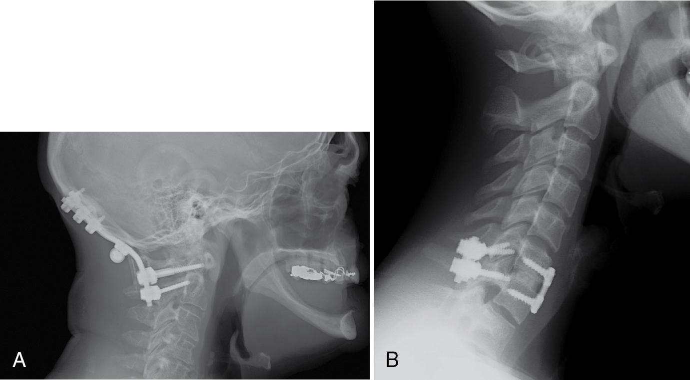
Posterior cervical instrumentation most commonly involves use of rod-screw systems. Screws may be placed in the occiput, C1 (lateral mass), and C2 (pedicle vs. pars vs. translaminar screws). In the subaxial cervical region, lateral mass screws are more commonly used compared with pedicle screws at the C3–C6 levels, whereas pedicle screws are typically used at C7 and distally in the thoracic region. Anterior cervical plates are the most commonly used implants in the C3–C7 region. Reconstruction of the anterior spinal column following discectomy or corpectomy may be performed with bone graft or synthetic devices commonly referred to as “fusion cages” ( Fig. 28.1 A,B).
Trauma
Ligamentous instability
Select odontoid fractures
Rheumatoid arthritis (basilar invagination)
Infection
Neoplasm
Select skeletal dysplasias
Arnold-Chiari malformations
Select metabolic bone diseases
Anterior options: Implants are infrequently placed in this region because it is challenging to achieve surgical exposure here. Bone graft or cages are used to reconstruct osseous defects. Occasionally specialized plates (e.g., C2 to clivus plate) or C1-occipital condyle screws are used.
Posterior options: Rod-screw systems are the most commonly used implant. A hybrid rod-plate combination is an additional option. Contoured rods with wire or cable fixation are an option for special circumstances. Bone grafts and wires may be used in conjunction with other implants but are rarely used in isolation because they are not sufficiently stable to permit patient mobilization without extensive external immobilization, such as a halo device.
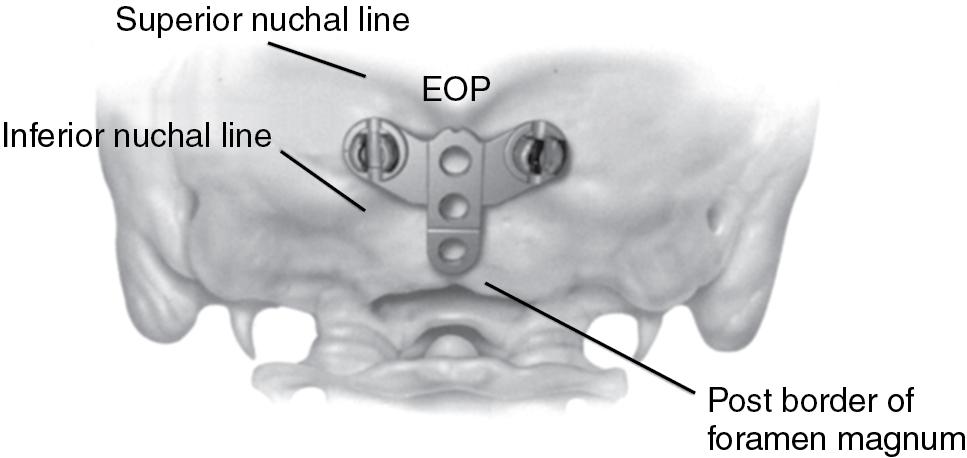
Occipital bone is thickest and most dense in the midline below the external occipital protuberance (inion). This region provides an excellent surface for screw purchase. Occipital bone thickness decreases laterally and inferiorly from the inion. Screws should be placed below the superior nuchal line that overlies the transverse sinuses, which can be injured during drilling or screw placement ( Fig. 28.2 ).
The surgeon has several options including:
Modular midline screw plates: A midline plate permits screw purchase in the thick midline bone and permits minor adjustments to facilitate linkage to an independent dual-rod construct ( Fig. 28.3 A).
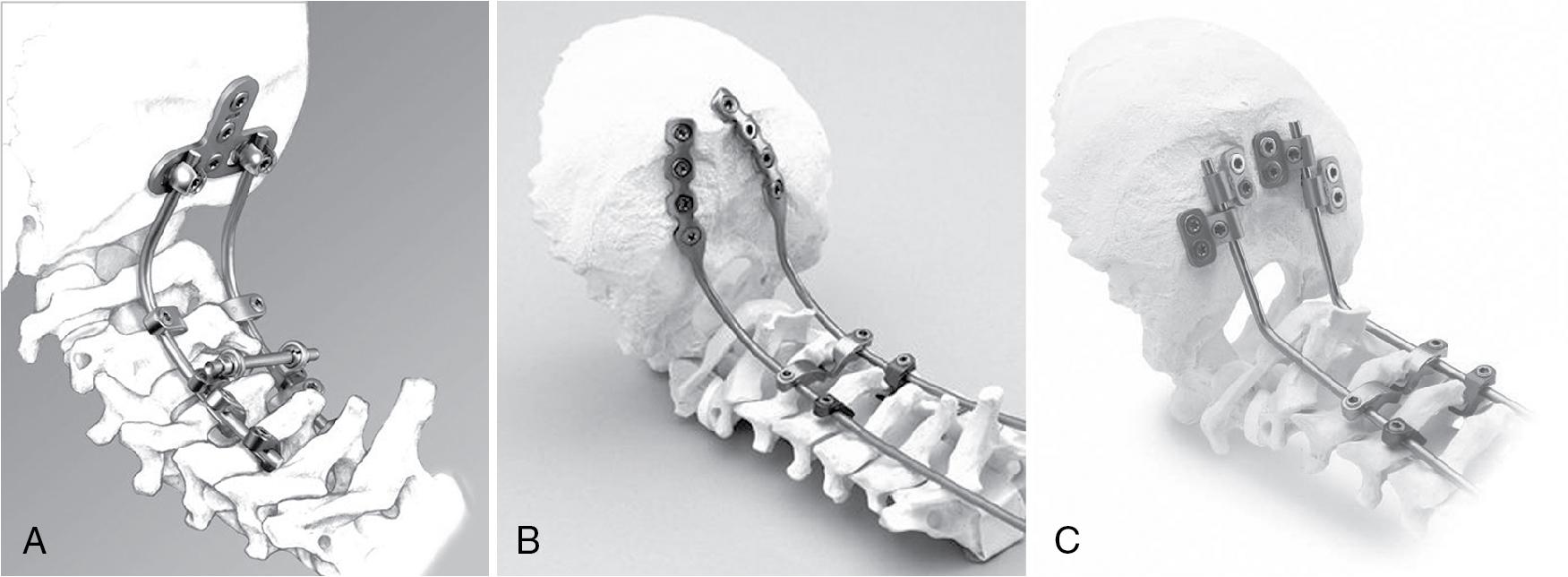
Hybrid rod-plate fixation: Plates attach laterally to the midline of the occiput and connect with rods for fixation in the cervical spine distally. Specialized implants consisting of a single rod that transitions to a plate are available (see Fig. 28.3 B).
Rod with specialized connectors: Occipital screws are linked to rods via offset screw-rod connectors (see Fig. 28.3 C).
Two basic techniques are utilized:
In the first technique, the screw is placed directly in the lateral mass of C1. The entry point is at the junction of the C1 lateral mass with the undersurface of the C1 posterior arch ( Fig. 28.4 A). The extensive venous plexus in this region makes dissection challenging. In addition, the C2 nerve root is in proximity to the screw entry point and must be retracted distally. A modified technique involves creation of a notch on the undersurface of the C1 arch to facilitate drill/screw placement to minimize dissection in the region of this venous plexus. Screws are directed with 5°–10° of convergence and parallel to the C1 arch (see Fig. 28.4 B).
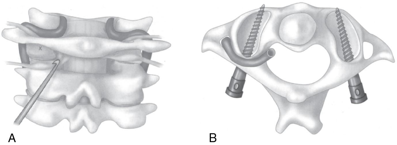
The second technique uses an entry point on the C1 arch and places a screw through the pedicle analog of C1 and into the C1 lateral mass. The vertebral artery is at greater risk with this technique and one must not mistake a common anomaly in which a bony bridge, the arcuate foramen, overlies the vertebral artery or the screw will injure the vertebral artery. This osseous anomaly has been termed the ponticulus posticus . With either technique, excessive superior C1 screw angulation will violate the occiput-C1 joint. An excessively long C1 screw may potentially compromise the internal carotid artery or hypoglossal nerve.
Three options exist: C2 pars screws, C2 pedicle screws, and C2 translaminar screws.
The pars interarticularis is defined as the portion of the C2 vertebra between the superior and inferior articular processes. The screw entry point is 3–4 mm superior and 3–4 mm lateral to the inferior medial aspect of the C2–C3 facet joint. Screw trajectory is parallel to the C2 pars interarticularis with approximately 10° of medial angulation ( Fig. 28.5 ).
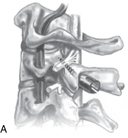
The C2 pedicle is defined as the portion of the C2 vertebra connecting the posterior osseous elements with the vertebral body and consists of the narrow area between the pars interarticularis and the vertebral body. The entry point is approximated by the intersection of a vertical line through the center of the C2 pars interarticularis and a horizontal line through the upper edge of the C2 lamina. The screw entry point is 2 mm lateral to the location defined by these landmarks. The screw is placed with 15°–45° of medial angulation and parallel to the superior surface of the C2 pars interarticularis. The medial wall of the C2 pars can be palpated as an additional guide to placement ( Fig. 28.6 ).
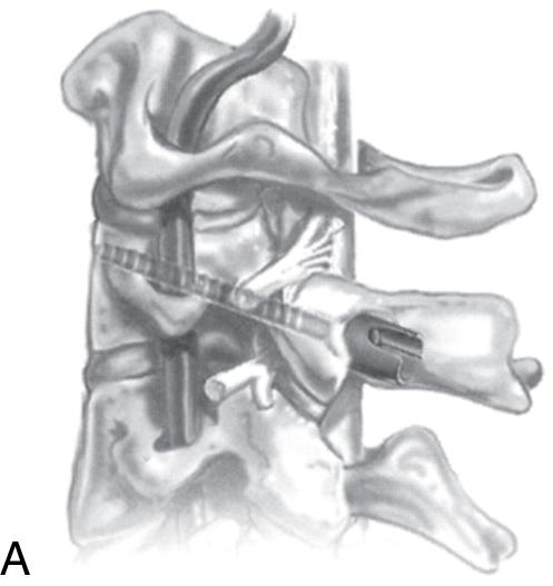
The C2 pedicle screw trajectory is more superior and medial than the pars screw and has greater risk of injury to a high-riding vertebral artery. A longer screw length may be achieved using a C2 pedicle screw than a C2 pars screw. A C2 pedicle screw can be safely placed with bicortical screw purchase. A C2 pars screw is typically a unicortical screw that stops short of the transverse foramen to prevent potential injury to the vertebral artery.
Become a Clinical Tree membership for Full access and enjoy Unlimited articles
If you are a member. Log in here