Physical Address
304 North Cardinal St.
Dorchester Center, MA 02124
Repair of traumatic mandibular fractures is a complex process requiring assessment of the degree of comminution, extent of soft tissue injury and restoration of preinjury occlusion. Traditionally, mandibular trauma is managed via intermaxillary fixation (IMF) and open reduction-internal fixation (ORIF) using titanium plates bent intraoperatively. This process requires subjective determination of intraoperative occlusion and plate contouring is time consuming and may lack accuracy. Additionally, the use of extraoral incisions to adequately visualize the reduction carries an increased risk of morbidity due to possible structural or nerve injury and can result in an aesthetically unpleasing scar. , Computer aided design and computer aided manufacturing (CAD/CAM) has revolutionized complex craniofacial and orthognathic surgery as it enables advanced preoperative planning along with fabrication of three-dimensional (3D) models, customized plates, osteotomy guides, and splints. Through the implementation of these technologies the focus of craniofacial surgeries is able to shift from a surgeon’s subjective assessment to a more facile interface of preoperative planning and enhanced intraoperative execution. This shift has in turn led to improved precision, efficiency and patient outcomes. Although CAD/CAM is now a staple of many scheduled craniofacial surgeries, there is increasing literature on its application in patients undergoing traumatic craniofacial reconstruction.
The use of CAD/CAM in treatment of acute facial trauma has been mostly described in orbital and midface trauma. However, new studies are emerging describing CAD/CAM implementation in the management of acute mandibular trauma. Reconstruction of mandibular trauma can be difficult, depending on the extent of intraoral and extraoral soft tissue damage, the degree of comminution and the need to reestablish proper occlusion. It can be further complicated in edentulous patients, due to poor bone stock and absence of dentition to assist in fracture reduction. Frequently, acute mandibular fractures are managed with serial debridements and use of load-bearing plates to bridge any segmental bone loss.
The use of CAD/CAM application in this setting has been documented in only a handful of studies. These emerging studies, however, describe a variety of ways CAD/CAM can be utilized to address the reconstructive challenges posed by acute mandibular trauma. One such method is to use CAD/CAM to assist in prebending plates. In this method the patient’s admission computed tomography (CT) scan is uploaded into a CAD/CAM program which allows the mandibular segments to be virtually reduced and preinjury occlusion to be restored. The virtually reduced mandible can then be printed as a 3D model. The CAD/CAM and 3D printing can either be outsourced or, if resources are available, can be performed and printed in-house. Standard plates can then be bent preoperatively to fit this model, thereby reducing OR time and ensuring proper fit. It is also possible to use CAD/CAM to virtually reduce a fractured mandible and then commission custom milled or laser sintered titanium plates. While the printing of custom plates can take several days and delay an operation, they eliminate the need for plate bending and provide a method of guiding and confirming the reduction. Titanium plates are also inherently stronger and lower profile making them less palpable. Finally, for comminuted or edentulous mandibular fractures surgical splints can be fabricated using CAD/CAM technology. These splints can then assist in the anatomical reduction of bony segments and provide immobilization during maxillomandibular fixation (MMF) or ORIF application.
Therefore, advantages of using CAD/CAM in this setting include shorter OR time, less invasive repair through intraoral incision, use of stronger, anatomically configured, lower profile plates, and less subjectivity in reconstruction. However, CAD/CAM implementation does require coordination with bioengineers, longer lead time for custom models, plates, guides, and splints. Additionally, the cost of custom pieces can be substantial, and may not be fully offset by reduction in cost from reduced OR time.
Virtual reduction using CAD/CAM software is done based on occlusion and condyle position. The first step of virtual reduction is to ensure that mandibular condyles are appropriately seated within the mandibular fossa. Once this is completed the mandibular bone fragments can be aligned to create “virtual IMF” using wear facets and dental midlines as a guide. In the case of edentulous mandibular fractures, mandibular symmetry can be assessed using anatomic landmarks such as the midline of nasal bones, intercondylar distance, and the mental protuberance. Virtual reduction with a team of experienced radiologists, oral/maxillofacial surgeons, or outside vendor bioengineers can be completed in approximately 20 minutes, however, this process is dependent on the user’s familiarity with the software and anatomy.
Based on resources, plates can be custom milled, 3D printed with laser sintering or prebent using a standard plate. Whether custom milled, laser sintered or prebent plates are being used, the process of fracture reduction and plating is very similar. First, the patient should be placed in intermaxillary fixation (IMF). This step can be challenging in patients with edentulous mandibular fractures where preexisting dentures or gunning splints are typically used to achieve IMF. However, fabrication of gunning splints in an acute trauma setting can be difficult to obtain since they require dental impressions and stone models. CAD/CAM technology can be used instead to design a maxillary mandibular splint based on the virtual reduction. This splint can then be used as a guide intraoperatively to guide fracture reduction and establish proper vertical dimension.
Once IMF is achieved the plate is then fixed to the largest fracture segment and each subsequent piece is reapproximated one at a time using bicortical screws. For more comminuted or complex injuries, monocortical simplification plates can be used first to bring smaller bone fragments together prior to placing larger plates. A minimum of three screws should ideally be used to hold the anterior and posterior pieces of the fracture with one screw in each of the larger comminuted pieces. Bone stock should be assessed preoperatively using the admission CT scan and screw position must be planned for areas of adequate bone stock. Ideally at least four screw holes should be available in major segments and at least two holes in comminuted segments thereby allowing for redundancy in the number of screw holes in case of unforeseen failure at one of the sites. In severe cases of mandibular trauma the mental nerve may be severed; however, if the mental nerve is preserved it should be meticulously dissected and skeletonized in order to minimize risk of injury. The plate should then be placed inferior to the nerve.
Once the plate is secured, appropriate anatomical occlusion should be confirmed by clinical assessment before the patient has left the OR. A postoperative CT scan in the early postoperative period can also be used to confirm appropriate skeletal occlusion.
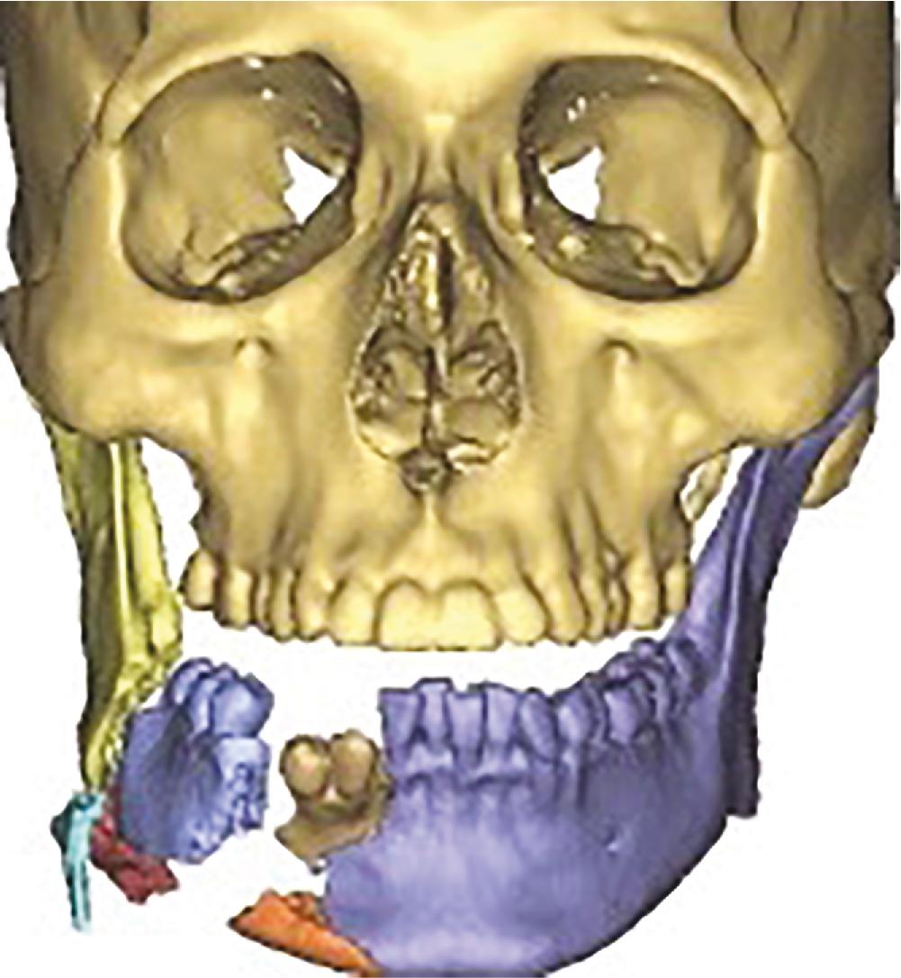
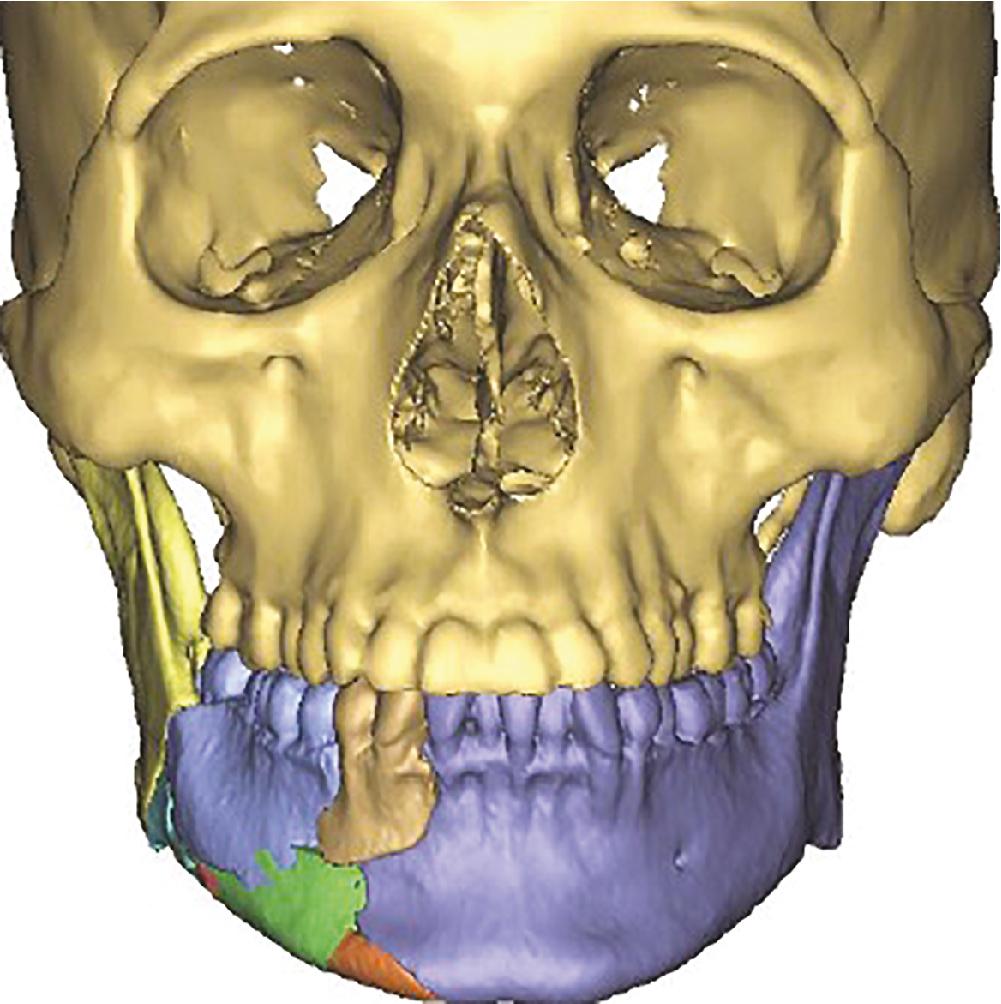
Please see Fig. 19.1 .

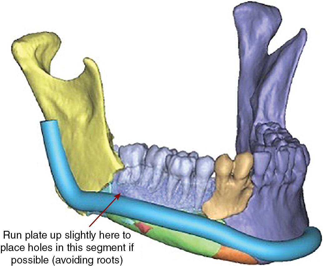
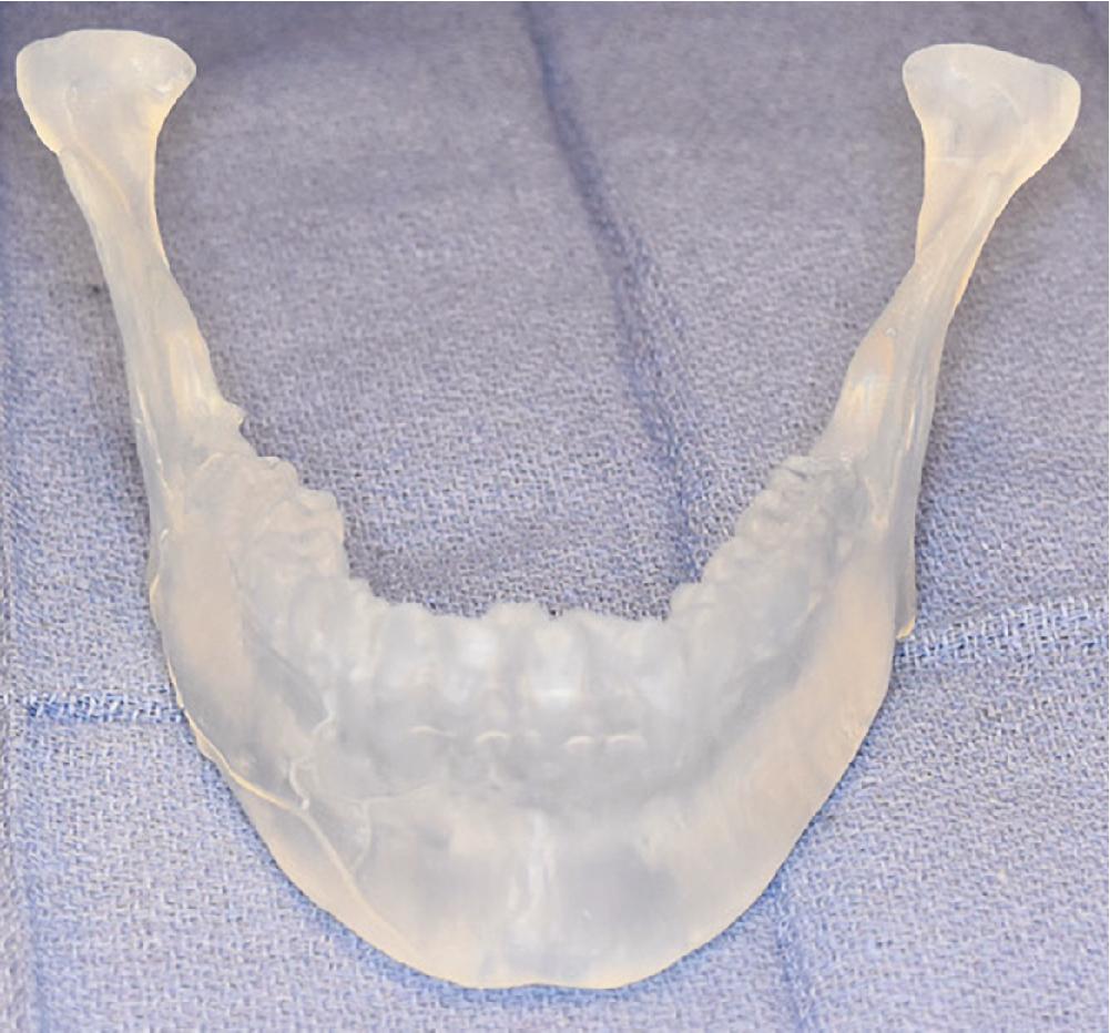
Utilization of CAD/CAM for facial trauma typically involves a team of surgeons and biomedical engineers from a modeling company. Alternatively, some institutions have in-house radiologists well versed in the software required to virtually reduce a mandible. After virtual reduction of the mandible is complete, files are exported to a 3D printing software as stereolithography (STL) files. In this format the file is aligned on the print bed and supports are generated prior to printing. Models are printed using a biocompatible resin and then washed with fresh isopropyl alcohol prior to curing. After curing is complete standard titanium locking reconstruction plates can be prebent using the model as a guide. Once the plate is appropriately prebent it is then sterilized in preparation for surgery. Similarly, surgical splint design, including shape, thickness, and location of splint holes, is done using computer software during the planning meeting. The custom surgical splint is then 3D printed using a biocompatible resin. When using custom printed titanium plates, the virtual reduction is completed and then plates are virtually superimposed on the computer model. The plate’s position is then adjusted virtually to contour with the reduced mandible and so that screw holes are placed in areas of adequate bone density. Once appropriate contour positioning of the plate is achieved the file is once again exported to 3D printing software and the plate is constructed using milling or laser sintering technology. A milled plate is created through a process of “subtractive” printing. Through this process a block of titanium has layers gradually removed (milled) until the remaining titanium fits the computer model. Laser sintering, on the other hand, is a form of “additive” printing in which titanium particles are “welded” together using a laser until the plate is formed. This custom plate is then shipped to the hospital where it undergoes sterilization prior to the patient’s surgery.
Stereolithographic models ( Fig. 19.2–19.5 ).


Become a Clinical Tree membership for Full access and enjoy Unlimited articles
If you are a member. Log in here