Physical Address
304 North Cardinal St.
Dorchester Center, MA 02124
The slit lamp biomicroscope has been the primary instrument for examining the anterior ocular structures since its invention in the early part of the 20th century. In particular, this versatile instrument is invaluable in assessing the effect of contact lens wear on the tear film, cornea, conjunctiva and eyelids. Other simple 20th century optical instruments which were developed to aid contact lens fitting, such as the Burton lamp, or to enhance our ability to assess the tear film, such as the Tearscope, are still in common use today.
As a result of developments in digital electronics, optical technology, still and video capture imaging and computer-assisted image-analysis techniques, a range of sophisticated ophthalmic instruments have been developed over the past two decades and have expanded our capacity to examine the anterior eye. Such instruments that have been demonstrated to have considerable utility in this regard are the specular microscope, corneal confocal microscope, optical coherence tomographer, corneal topographer, pachometer and aesthesiometer. These devices provide valuable capability that supplements visual examination using slit lamp biomicroscopy.
The aim of this chapter is to review the various instruments that are now available to facilitate examination of the anterior eye and determination of anterior ocular dimensions and which have been used to capture the majority of images presented in this book. Primary attention is given to the slit lamp biomicroscope, as this technique has always been, and is likely to remain, the mainstay of ocular examination in contact lens practice.
A number of manufacturers make a special hand-held magnifying device for contact lens work. This device is usually referred to as the ‘Burton lamp’, after the company that manufactured the original version (Burton Manufacturing Co., Chicago, Illinois, USA). The Burton lamp is essentially a large magnifying lens of about + 5.00 diopters (D) housed in a broad frame, within which is mounted a combination of 4 watts (W) white light and ultraviolet light fluorescent tubes, each 11 cm long. The operator can switch between the two light sources for white light and fluorescein stain examinations. A key advantage of this instrument is that both eyes of the patient can be viewed simultaneously, facilitating inter-ocular comparisons in the course of contact lens fitting. The Burton lamp is also useful for conducting an initial screening examination ( Fig. 1.1 ).
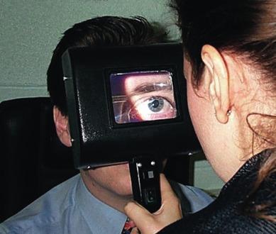
The main disadvantage of the Burton lamp is that it is not possible to view fluorescein fitting patterns of rigid contact lenses made of material containing ultraviolet absorbing properties. This is because the Burton lamp has its highest emission in the 300 to 400 nm range, and this short-wavelength blue light is attenuated by the lens material, resulting in decreased fluorescence.
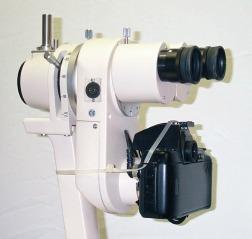
The slit lamp biomicroscope ( Fig. 1.2 ) is a combined illumination and observation system that allows the eye to be examined from close distance at different magnifications. With the appropriate application of supplementary lenses and/or viewing techniques, the instrument may be used to assess the condition of the vitreous, lens and retina from the posterior pole to the ora serrata. Various ancillary instruments that enable examination of the tear film, anterior chamber angle and retina and measurement of intra-ocular pressure, corneal sensitivity and corneal thickness can be attached. Since this book is concerned with the assessment of ocular complications of contact lens wear, the discussion that follows will relate primarily to the use of the slit lamp biomicroscope in examining the anterior ocular structures.
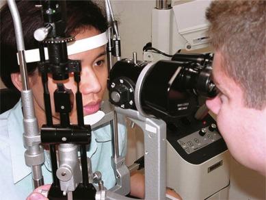
It has long been recognised that it is not possible to sensibly prescribe and fit contact lenses, or provide ongoing care to contact lens patients, without access to a slit lamp biomicroscope. This instrument is used virtually every time a contact lens patient is seen, including during the initial examination, fitting and aftercare visits. Certainly, the vast majority of complications of contact lens wear cannot be detected or assessed without the aid of a slit lamp biomicroscope. It is therefore imperative that contact lens practitioners have access to this instrument and are well versed in its operation.
This section will outline the design and construction of the slit lamp biomicroscope, review key techniques of ocular illumination and examination inasmuch as they relate to contact lens practice and suggest a recommended examination procedure.
The general construct of a slit lamp biomicroscope is indicated by its name; that is, there is a separate illumination system (the slit lamp) and a viewing system (the biomicroscope). These two components are mechanically linked ( Fig. 1.3 ) so as to create a common focal point and centre of rotation; however, the mechanical linkage can be unlocked to allow the focal illumination to be directed away from the focal point of the viewing system, and this is an essential requirement for some observation techniques, such as ‘sclerotic scatter’ (see later). The mechanically linked illumination and observation systems are always moved simultaneously – up and down with a height control, and focusing (in and out) and lateral (side to side) movements with a joystick. This linked control system facilitates rapid and accurate positioning of the slit beam to the area of interest on the eye and ensures that the microscope and illumination systems are simultaneously in focus.
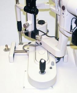
The patient is seated opposite the observer, and the head of the patient is positioned in a conventional head mount comprising a chin rest and a brow rest. The linked illumination/observation system can be moved about independently of the head position, and a fixation target is provided to assist eye positioning and help the patient keep his or her eyes still. The entire head mount and linked illumination/observation system are contained on an instrument table, which can be adjusted in height – as can the practitioner and patient seats – to allow a comfortable posture to be adopted by both the examiner and the patient.
The illumination system is called the slit lamp – so called because of its capacity to project a slit of light onto the ocular surface. The light source and optical elements of the slit lamp are classically contained in a vertically oriented housing ( Fig. 1.4 ). A bright light source (generating approximately 600,000 lux) is a fundamental requirement for a slit lamp if subtle conditions are to be seen clearly. Although halogen or xenon lamps are more expensive than tungsten lamps, they are the preferred illumination source as they provide a brighter light, last longer, have better colour rendering and generate less heat. The light is focused vertically into a slit configuration. It then reflects off a mirror mounted at 45° and is projected onto the eye.
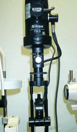
Illumination brightness is controlled by a rheostat or multiposition switch such that brightness can be adjusted to obtain the correct balance between patient comfort and optimal visibility of the area of interest. Generally, the broader the slit, the brighter the light, the greater the patient discomfort and the lower the illumination setting must be.
The optical and aperture-masking components within the illumination system are designed such that the emergent slit of light has sharp edges and an even spread of illumination. The slit width and height are continuously variable so that a section of light of any shape can be projected. The ability to vary the slit width has other practical applications, such as forming a reference for estimating the size of features of interest. Furthermore, the slit can be rotated so that, for example, a horizontal rather than a vertical slit can be projected onto the eye. This facility can also be useful for measuring the degree of rotation of soft toric lenses.
A number of filters can be incorporated into the illumination system, and the filters serve to enhance the visibility of certain conditions:
Green (‘red-free’) filter – enhances contrast when looking for corneal and iris neovascularization, since red vessels appear black if viewed through such a filter. A green filter may be used to increase the visibility of rose bengal staining on both the cornea and conjunctiva.
Neutral density (ND) filter – reduces beam brightness and increases comfort for the patient.
Polarising filter – reduces unwanted specular reflections and can be useful for enhancing the visibility of subtle defects.
Diffusing filter – diffuses the illumination source over a wide area and is used to provide broad, unfocused illumination for low-magnification viewing of the general ocular surface.
Cobalt blue filter – provides a suitable means of exciting sodium fluorescein for examination of ocular surface integrity. Illumination of fluorescein with cobalt blue light of 460 to 490 nm produces a greenish light of maximum emission 520 nm. Any abraded area will absorb fluorescein and display a fluorescent green area against a general blue background. The filter is occasionally used on its own to aid in the diagnosis of keratoconus. A frequent finding in this corneal ectasia is a Fleischer ring, which is formed by an annular iron deposition within the stroma at the base of the cone. The iron pigment is often difficult to see in white light but will usually appear in greater contrast when viewed through the cobalt blue filter.
Yellow (Kodak Wratten #12) filter – this is not a filter contained within the illumination system but is used as a supplementary barrier filter that is placed in front of the viewing system. It significantly enhances the contrast of any fluorescent staining observed with the cobalt blue filter as it allows transmission of the green, fluorescent light but blocks the blue light reflected from the corneal surface. Custom-made barrier filters for certain slit lamps are available from some manufacturers. Inexpensive hand-held versions may be constructed by using a cardboard mask and Lee filters #101 Yellow.
A biomicroscope of high optical quality is essential if the observer is to achieve a comfortable, clear, focused binocular image of the eye ( Fig. 1.5 ). The optical system contains an objective, typically with × 3 to × 3.5 magnification, and an eyepiece with variable or interchangeable power. The normal range of total magnification is from × 6 to × 40. In some systems, magnification is continuously variable throughout this range. These systems have two key advantages: (1) There is an uninterrupted view of the eye while the level of magnification is changed, and (2) the observer is not constrained to using discrete levels of magnification and can, in effect, choose any level of magnification within the available range. However, such systems usually require additional optical elements to achieve the ‘zoom’ function, and this may slightly compromise the optical quality of the image.
For the purposes of discussion throughout this book, the level of magnification being used can be broadly classified as follows:
low: less than × 10 magnification
medium: × 10 to × 25 magnification
high: greater than × 25 magnification.
In most systems, magnification is changed in steps, with the typical progression being × 6, × 10, × 16, × 25 and × 40; these systems generally afford high optical quality, but there is the disadvantage of momentarily losing sight of the eye while the magnification is being changed. Some systems require the eyepieces to be interchanged to obtain different levels of magnification. Needless to say, these systems are cumbersome and mitigate against a smooth examination procedure. Manufacturers of slit lamp biomicroscopes could produce instruments with higher levels of magnification than × 40, but natural micronystagmoid eye movements make observation at such high magnification levels impractical.
The working distance of the biomicroscope (the distance from the eye to the front surface of the most anterior lens element of the biomicroscope) is typically set at about 10 cm, which is long enough to allow room for manipulating the eye, but not too long so as to require an uncomfortable arm position during such manipulations.
Being a transparent structure, the cornea lends itself to being examined with use of a wide variety of illumination and observational techniques. These are achieved by varying the illumination and observation conditions to optimise the visibility of the feature of interest in or on the cornea. There are essentially 13 illumination/observation techniques; these will be discussed in turn, with specific emphasis on those more routinely used in contact lens practice.
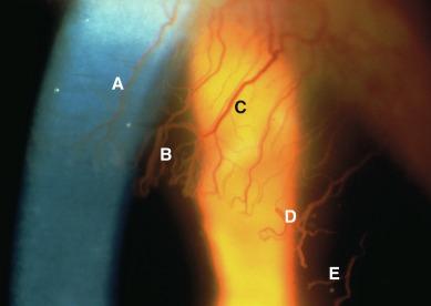
Although the techniques discussed next may seem daunting and somewhat confusing to the novice, it is important to realise that many combinations of these illumination and observation conditions are visible within a single field of view and are altered merely by the observer changing his or her direction of gaze. This is illustrated in Figure 1.6 , where five illumination/observation conditions are simultaneously apparent in a single field of view in a case of contact lens–induced corneal neovascularization.
A ground glass filter is placed in the focused light beam of the slit lamp. This will defocus and diffuse the light to give a broad, even illumination over the entire field of view. The angle of the illumination arm is not critical when the diffuser is in place and can be anywhere from 10° to 70° in relation to the observation arm; it is simply convenient to place it at an angle of at least 45° so as to avoid partially obstructing the field of view. The slit is generally opened wide, and high illumination will not cause too much patient discomfort in view of the diffuse nature of the light ( Fig. 1.7 ).
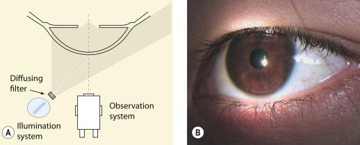
Diffuse illumination is generally used to provide low-magnification views of the opaque tissues of the anterior segment (AS), including the bulbar conjunctiva, sclera, iris, eyelid margins and the tarsal conjunctiva of the everted lids. Unusual signs in these tissues could include dilated blood vessels in the bulbar conjunctiva, pigmented areas in the conjunctiva or eyelids, roughness or opacity of the conjunctiva and abnormal eyelash position or orientation. Such signs could be indicative of some conditions, such as trichiasis, bulbar redness, pterygium or papillary conjunctivitis. In assessing the eyelid margins, the apposition of the lids and puncta against the globe should be considered. Additionally, one should look for clear glands near the base of the lashes and flaking or scaling of the eyelid skin. These may indicate the presence of ectropion, blepharitis or epiphora.
This describes any illumination technique where the slit beam and viewing system are focused coincidentally. The illumination is turned up to a reasonably high level of brightness (ensuring that the patient remains comfortable) and the slit beam is placed at a separation of 40° to 60° on the side of the microscope corresponding to the section of the cornea to be viewed. The beam is swept smoothly across the ocular surface and the illumination system moved across to the opposite side as the beam crosses the mid-point of the cornea. Typically, a beam width of 0.1 mm to 0.5 mm is chosen initially and this may be reduced so as to bring more contrast (as a result of less light scatter) to the area of interest. The term ‘parallelepiped’ refers to the geometric shape of the illuminated optical section of the cornea under examination.
A slit width that is wider than 0.5 mm creates a condition known as ‘broad–beam’ illumination, whereby the width of the beam is greater than the depth of the cornea (effectively creating a parallelepiped, which is turned on its side). Whilst scanning the external ocular surface, a low-to-medium magnification is initially chosen, and the magnification is increased if any area of interest needs to be examined more closely.
The section of the cornea within the illuminated beam is being observed ( Fig. 1.8 ). This permits assessment of the location, width and height of any object within the cornea or adjacent structures. The parallelepiped is the most commonly used direct illumination technique and is employed, for example, to assess corneal scarring, infiltrates and corneal staining.
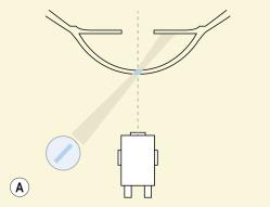
The section of the cornea outside the illuminated beam is being observed. This is achieved by directing gaze to either side of the illuminated beam. To achieve this configuration, the parallelepiped is positioned to one side of the feature of interest. Thus, the feature of interest is being illuminated by side-scattering of light from the parallelepiped. This technique may reveal the presence of subtle changes in corneal transparency, which may not have been visible using direct illumination.
This condition is identical to ‘focal illumination – parallelepiped’, except that a very thin beam of approximately 0.02 to 0.1 mm is used to essentially create a ‘cross-section’ of the corneal tissue. The illumination beam is placed at a separation of 40° to 60° on the side of the microscope corresponding to the section of the cornea to be viewed. Increasing the angle of the illumination arm increases the depth of the optic section in the cornea, but the same amount of light is spread over a greater depth of cornea, and this reduces brightness and contrast and makes the deeper corneal layers, in particular, more difficult to visualise. Because the light beam is so thin, the illumination must be turned up to maximum brightness.
The section of the cornea within the illuminated beam is being observed ( Fig. 1.9 ). This provides the ability to accurately assess the depth of an object within the corneal layers. Typical uses include assessing the depth of a foreign body, locating a corneal scar and determining whether tissue within an area of staining is excavated, flat or raised.
The section of the cornea outside the illuminated beam is being observed. This is achieved by directing gaze to either side of the illuminated optic section. To achieve this configuration, the optic section is positioned to one side of the feature of interest. Thus, the feature of interest is being illuminated by side-scattering of light from the optic section. Indirect focal illumination from an optic section is perhaps only a theoretical consideration; a superior indirect view of a corneal anomaly will be achieved using a wider beam (i.e. parallelepiped or broad beam).
This refers to any technique in which light is reflected from the iris, anterior lens surface or retina and is used to back-illuminate a section of the cornea, which is more anteriorly positioned. The illumination and observation systems can be adjusted so that the feature of interest in the cornea is seen against a light background (e.g. light-coloured iris) or a dark background (e.g. dark-coloured iris, or the pupil in the case of indirect retroillumination).
This technique is particularly useful for examining neovascularization, scars, degenerations and dystrophies.
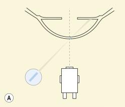
Direct retroillumination refers to the configuration whereby the retroillumination is directly behind the feature of interest in the cornea ( Fig. 1.10 ). Thus, for example, a corneal scar is viewed against an illuminated iris in the background. With this technique, corneal opacities will appear black against the bright field.
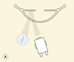
Indirect retroillumination refers to the configuration whereby the retroillumination is not directly behind the feature of interest in the cornea but is offset to one side ( Fig. 1.11 ). Thus, the feature of interest is being observed by virtue of back-scattered light that is deflected away from the feature of interest in the cornea into the eye of the observer.
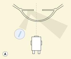
Marginal retroillumination is a specific variant of indirect retroillumination whereby the pupil margin is deliberately chosen as the background retroilluminated field against which the corneal feature is being observed ( Fig. 1.11 ). Simply put, the corneal feature of interest is viewed against a background of the illuminated iris–pupil margin. This technique is typically used in association with high levels of magnification and is used to assess the optical characteristics of transparent optical bodies in the tear film of the cornea, such as mucin balls, and epithelial microcysts, vacuoles and bullae.
This is a specific case of a parallelepiped setup, where the angle of the incident slit beam is equal to the angle of the observation axis through one of the oculars ( Fig. 1.12 ). At this angle (typically 40°–50°), the illumination beam is reflected from the smooth surfaces of the cornea and provides a mirror-like (‘specular’) reflection. Such specular images occur at every interface between structures of different refractive indices, the most prominent of which will be anterior epithelial or posterior endothelial surfaces. The technique of specular reflection is typically used to view the endothelium.
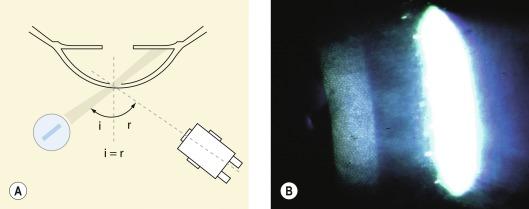
To begin with, the lowest magnification setting is selected, and the illumination arm is set at an angle to the normal that is greater than the angle of the observation system to the normal. The illumination arm is then brought back towards the observation system while observing the corneal surface. At the point where specular reflection is achieved, a bright reflex will fill one of the oculars (specular reflection cannot be achieved binocularly). The illumination/observation system should now remain in a fixed position, and the magnification is set to maximum so that the anterior and/or posterior corneal surface can be viewed in specular reflection. A very bright reflection from the anterior surface constitutes a debilitating distraction when trying to observe the endothelium; this situation can be resolved by increasing the angle between the observation and illumination systems, although there is not much room for manoeuvre before the specular reflection is lost.
The size of endothelial cells is such that, even at × 40 magnification, only gross anomalies of the endothelium, such as large guttae, blebs, bedewing, ruptures and deep folds, can be detected. Subtle cellular characteristics of the endothelial mosaic, such as cell density or polymegethism, cannot be assessed. The tear film lipid layer, inferior tear meniscus and anterior surface of the crystalline lens can also be readily examined using specular reflection. If a contact lens is being worn, front surface wetting can be assessed and the post-lens tear film may be observed using specular reflection.
This technique is used to investigate subtle changes in corneal clarity, such as central corneal oedema, occurring over a large area. The slit lamp is set up for a wide-angle parallelepiped (45°–60°) and the viewing system is focused centrally. The beam is manually offset (‘uncoupled’) and focused on the limbus. The slit beam is totally internally reflected across the cornea, and a bright limbal glow is seen around the entire cornea ( Fig. 1.13 ). Any specific area of abnormality, such as a corneal scar, will interrupt the beam in its passage and produce a light reflection in the otherwise clear cornea; abnormalities in the cornea are especially visible when viewed against a dark pupil in the background.
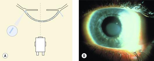
This is infrequently used in contact lens practice but is, nonetheless, a useful technique. Oblique illumination is achieved by setting up a parallelepiped and then moving the illumination system away from the observation system until the angle between them is close to 90°. The observation system is positioned at 90° to the facial plane (i.e. straight ahead) and the illumination arm is adjusted until the light beam is almost tangential to the object of interest. Any raised areas cast a shadow, making this technique particularly useful for viewing subtle irregularities on the surface of the iris, epithelium or contact lens in situ.
Become a Clinical Tree membership for Full access and enjoy Unlimited articles
If you are a member. Log in here