Physical Address
304 North Cardinal St.
Dorchester Center, MA 02124

Advances in three-dimensional (3D) imaging and modeling have significantly changed the practice of treatment planning in patients with congenital or developmental facial skeletal differences. With improvements in imaging technology, such as computed tomography (CT), cone beam computed tomography (CBCT), 3D photography, and 3D intraoral dental scanners, the ability of the clinician to evaluate and treat facial dysmorphology has been revolutionized. Furthermore, advances in 3D surgical planning software have made it easier for surgeons to utilize computer-aided design/computer-aided manufacturing (CAD/CAM) protocols to generate stereolithographic models, positioning and cutting guides, surgical splints, and custom fixation. These ancillary tools have significantly improved surgical treatment planning in terms of accuracy, efficiency, and time. This chapter discusses the role of 3D digital planning in the contemporary management of craniofacial and dentofacial deformities, with a focus on the step-by-step process of computerized surgical planning in orthognathic surgery, from image acquisition to surgical plan execution in the operating room.
A well-planned and executed orthognathic surgical treatment plan can consistently deliver successful clinical results in a safe and predictable manner. Over the past two decades, there has been an increasing emphasis on identifying and understanding patient expectations of orthognathic surgery, with the goal of consistently delivering surgical care in the most efficient and predictable manner possible, even under the most complex circumstances.
Historically, orthognathic surgical treatment planning was largely based on two-dimensional records of patients: photographs and radiographs (panoramic films as well as lateral and postero-anterior cephalograms; Fig. 6.2.1 ). Surgical splints, used to position the maxilla or mandible intra-operatively, were fabricated by simulating the movements on articulated dental cast models ( Fig. 6.2.2 ). This process, while effective for modeling changes in the occlusion, did not reliably allow the surgeon to visualize the direct changes in the skeleton in real time or the secondary changes to the unoperated jaw when the position of the other jaw was altered. This traditional technique of surgical planning requires a multi-step process in which each step has the potential for errors, resulting in a cumulative error that may dramatically alter the end surgical result in the operating room ( Fig. 6.2.3 ). For example, errors in obtaining accurate facebow registration and transferring this record to a semi-adjustable articulator, as may be seen in patients with orbital or auricular deformities ( Fig. 6.2.4 ), can result in significant alterations in the magnitude and direction of three-dimensional movements. Subsequent construction of surgical splints based upon these movements and their use intra-operatively can all lead to inaccuracies if there was an error in any of the component elements. This process is also time-consuming in both the clinical and laboratory settings.
 , posterior–anterior (B) , and lateral (C) cephalograms have been historically used to assist with the diagnosis and surgical–orthodontic correction of dentofacial deformities.")
 , used to simulate the arch of mandibular rotation. This arc of rotation can also be simulated in the virtual environment to generate the intermediate position in two-jaw surgery (B) . Alteration of the mounted cast position to the desired tooth movements is then completed and translated to the operative environment (C) with the use of an acrylic splint.")
. Data acquisition that occurs prior to virtual planning is where the majority of accumulated error occurs (left of the blue line).")

Three-dimensional imaging and computer-aided design/computer-aided manufacturing (CAD/CAM) have revolutionized the surgical treatment planning process for patients undergoing orthognathic surgery. The advent of computed tomography (CT and CBCT), 3D photography, 3D dental model scanners, 3D surgical planning software and 3D printing of models allow for clinically significant improvements in surgical treatment planning, leading to greater accuracy and efficiency. 3D technology and surgical planning software allows orthodontists and the surgeons to develop a virtual treatment plan and simulate complex orthognathic surgeries on a personal computer with the visualization necessary to deliver predictable and optimal end results and appropriately counsel patients and their families.
3D imaging not only helps the surgeon to better understand the complex craniofacial deformity and plan the surgery but also helps to generate patient-specific cutting guides and fixation devices, and surgical splints for orthognathic surgery. Contemporary CAD/CAM technology allows a straightforward process for printing of cutting guides ( Fig. 6.2.5 ), positioning guides ( Fig. 6.2.6 ), intermediate and final splints ( Fig. 6.2.7 ), templates to harvest bone grafts, and customized fixation devices ( Fig. 6.2.8 ). This technology also eliminates the need for facebow transfer to register the maxillary and mandibular jaw relationships and for mounting dental study models on an articulator for model surgery and splint construction. Improved fidelity of intraoral scanning devices has largely obviated the need to obtain stone dental models and wax bite registrations. Scanned digital occlusions can be altered in the virtual surgical planning environment for even complex occlusions, such as correction of transverse discrepancies with segmental osteotomies and patients with significant three-dimensional facial asymmetries ( Fig. 6.2.9 ).

 of the condylar remnant and reconstruction with a costochondral graft. A custom guide (middle) was fabricated to ensure appropriate positioning of the costochondral graft (right).")
 and final (B) surgical positions, with the associated splints in situ , can also be simulated.")
 and genioplasty (middle). The cutting guides allow for precise positioning of the skeletal segments using prebent plates (right, bottom), which may obviate the need for occlusal-based splints, even in cases with complex movements (right, top).")
 was used to address the end-stage skeletal discrepancy in this patient with craniofacial microsomia. Preoperatively, there is a significant facial asymmetry and malocclusion involving both the maxilla and mandible (top middle and right). Surgical correction was undertaken via segmental Le Fort I osteotomy, bilateral mandibular sagittal split osteotomies, and genioplasty. The postoperative result at end-treatment shows balanced facial proportions, improved symmetry, and occlusion (bottom middle and right).")
In orthognathic surgery, surgeons are often faced with complex skeletal malformations in such syndromes as craniofacial microsomia, Treacher Collins syndrome, syndromic craniosynostosis, and hypertelorism, which have a variable amount of skeletal and soft-tissue deficiency. To correct these skeletal deformities, surgical treatment often involves complex osteotomies with intricate movements and repositioning of multiple skeletal components in relation to one another or to help identify the location of critical structures, such as developing teeth and nerves, relative to osteotomy paths ( Figs. 6.2.10 & 6.2.11 ). There may also be a need for bone grafts to reconstruct the deficient craniomaxillofacial skeleton. In patients with asymmetric skeletal deformities, the osteotomized bony segments need to be repositioned in all three spatial planes to correct the anteroposterior, vertical, and transverse deformities and re-establish facial symmetry. In addition to the linear movement, the patient will need some angular change in the pitch, roll, and yaw to correct occlusal plane, cant rotation, and arch rotation, respectively ( Fig. 6.2.12 ). In this context, 3D presurgical planning technology is an essential tool for the surgeon, as it allows for more precise three-dimensional control over the osteotomized segment. Following intervention, the surgeon and the patient can visualize the postsurgical treatment predicted changes in facial appearance in 3D prior to surgery.
 was indicated in this patient with Apert syndrome to correct the differential midface hypoplasia. Custom cutting guides (bottom, left) can be helpful to avoid injury to the developing succedaneous dentition.")
 to carefully execute a sagittal split osteotomy and avoid iatrogenic injury.")

3D technology does not affect the importance of detailed presurgical clinical examination findings of the patient, which primarily drive the surgical treatment plan, as well as the imperative for open and clear communication between the surgeon and orthodontist. 3D technology has replaced the traditional two-dimensional (2D) cephalometric analysis and prediction, photographic prediction, facebow transfer, dental study model surgery, and laboratory surgical splint construction. Surgical planning simulation software efficiently integrates a patient’s 3D CT/CBCT data, 3D photograph, and dental occlusal relationship and reconstructs a virtual 3D patient. This allows for complete visualization of the patient’s soft-tissue surface contours, craniofacial skeletal deformity, and dental occlusion as a reconstructed 3D image on a personal computer. The surgeon can then use this data to plan the orthognathic surgery and design various patient-specific cutting and position guides and splints (intermediate and/or final) to execute the orthognathic surgical treatment plan.
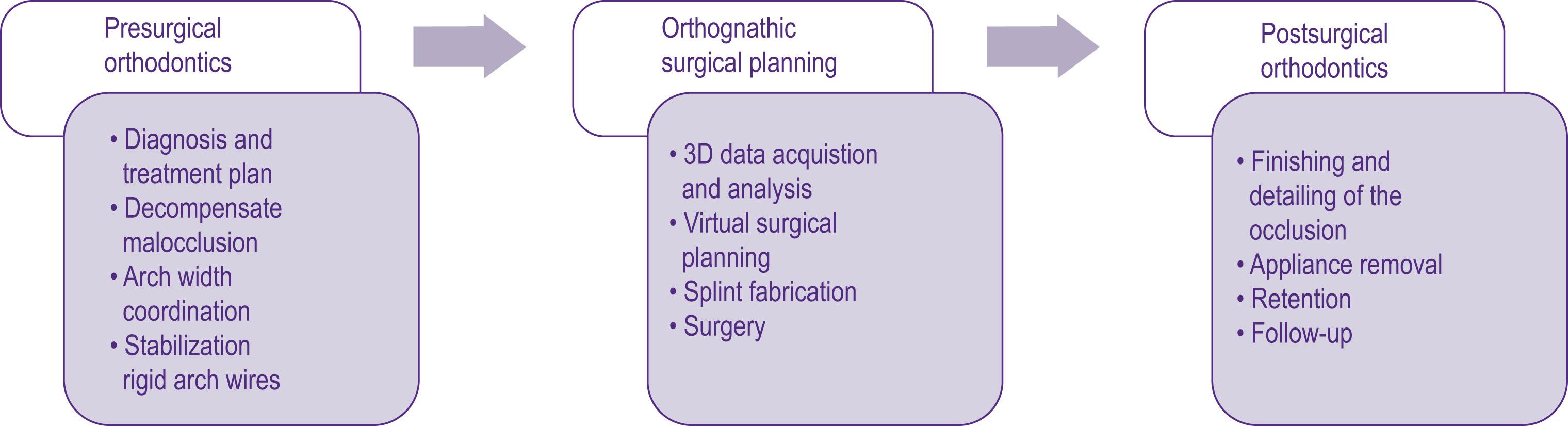
Orthodontic treatment for a patient requiring orthognathic surgery must be closely coordinated with the surgeon. The orthodontic treatment can be divided into three phases: the pre-surgical, perioperative, and post-surgical periods ( Algorithm 6.2.1 ). The presurgical orthodontic treatment plan to prepare a patient for orthognathic surgery is to decompensate dental malocclusion and coordinate the patient’s maxillary and mandibular dentitions through orthodontic tooth movement with fixed orthodontic appliances (“make the dental discrepancy match the skeletal discrepancy”). In this phase of orthodontic treatment, the maxillary and mandibular dental arches are coordinated so they fit optimally in an occlusion after surgical skeletal correction (i.e. matching the dental discrepancy to the skeletal discrepancy). Decompensation of the maxillary and mandibular dentitions is necessary prior to orthognathic surgery because dental compensation of skeletal malocclusion can occur naturally with growth, and the position of the teeth might have been compensated through orthodontic intervention during the early teenage years ( Fig. 6.2.13 ), leading to the potential for traumatic occlusions and periodontal compromise when the jaw positions are altered. Decompensation of malocclusion is also necessary to optimize the position of the jaws with surgery and to achieve the best possible final facial aesthetic and dental outcomes. This presurgical orthodontic phase can take between 4 and 18 months, depending on the severity of the malocclusion. Following surgery, the post-orthodontic treatment phase can vary from 6 to 12 months. Recently, there has been keen interest in performing surgery first and initiating orthodontic treatment after the orthognathic movement to treat the residual malocclusion. This paradigm shift takes advantage of the observation that orthodontic tooth movement immediately after surgery is accelerated due to increasing cellular activity. This method may work very well in patients with straightforward skeletal discrepancies that may only require movement in a single plane ( Fig. 6.2.14 ); however, a patient who requires complex jaw correction in all the three spatial planes may have a better outcome if pre-surgical orthodontic treatment goals are completed before surgery. Many patients with these types of craniofacial conditions may also have multiple missing teeth, unerupted teeth, or a significant transverse discrepancy and will have a more stable and predictable postsurgical dental occlusion if they undergo pre-surgical orthodontic treatment. 3D technology can also be applied in pre-surgical and postsurgical orthodontic treatments to accurately plan for the position of the teeth. The orthodontic tooth position can be controlled using 3D technology and robotic wire bending created by Suresmile Technology. This helps to achieve optimal pre-surgical dental occlusion before orthognathic surgery.
 Pre-orthodontic study models. (B) Posterior transverse and anterior midline discrepancies (red arrows) after hand articulation of pre-orthodontic treatment study models in the anticipated postsurgical position. (C,D) After completion of pre-surgical orthodontic treatment with the extraction of the maxillary right and left first premolars and decompensation of malocclusion. Note the coordination of the posterior dental arch width and the maxillary and mandibular midlines.")
")
The goals of pre-surgical orthodontic treatment in preparing the patient for orthognathic surgery include:
Coordinating tooth size and dental alveolar arch length discrepancy. If there is a significant discrepancy between tooth size and dental arch length and the patient exhibits crowding of teeth, permanent premolars may have to be extracted to correct this discrepancy.
Coordinating the anteroposterior inclination of the maxillary and mandible anterior teeth. Correction of the anteroposterior inclination of the maxillary and mandibular dentitions will allow for optimal skeletal jaw movement for the best facial aesthetic results. In a class III skeletal malocclusion, the dental compensation occurs in the maxillary arch by proclination of the maxillary teeth, and teeth in the mandibular arch tend to be retroclined. By contrast, in a class II skeletal malocclusion, the mandibular dentition is compensated by excess proclination.
Coordinating the transverse anteroposterior dental relationship. The posterior arch width needs to be coordinated so that when the maxillary and mandibular dentitions are brought into the predicted final occlusion, the teeth have the best intercuspation. This allows for better dental function and long-term stability of the occlusion.
Coordinating the vertical dental relationship. The maxillary and mandibular arches need to be leveled by either extrusion or intrusion of the anterior or posterior teeth. This will allow better post-treatment occlusion with little interference and greater stability of surgical correction.
Progress toward the pre-surgical orthodontic treatment goals must be closely monitored with periodic orthodontic study models. These study models must be hand-articulated in the anticipated postsurgical occlusion and checked for arch width coordination and any premature interference with opposing teeth.
After the completion of pre-surgical tooth movement goals, the orthodontist must fit the patient with heavy, rectangular, stainless steel archwires (e.g. 19 × 25 gauge) with surgical hooks in preparation for the pre-surgical evaluations. It is preferred that wires be secured with stainless steel ties in all orthodontic brackets. Ideally, this is accomplished at least 7 days prior to pre-surgical evaluation and final digital or cast dental impressions, to account for any minor dental shifts with changing of the wires. If any of the orthodontic brackets accidentally become debonded in the operating room, the bracket will remain on the orthodontic archwire.
After the patient has completed the pre-surgical orthodontic preparation, he or she will be ready for updated pre-surgical evaluations to construct a 3D virtual patient for surgical planning. The data that are usually required to create a virtual patient using virtual planning software are a clinical examination, 3D CT scan, intraoral dental scan and 3D photographs ( Fig. 6.2.15 ).

The data that are usually acquired for 3D computerized surgical planning include:
A 3D image acquisition of the craniofacial skeleton. A 3D skeletal image can be acquired using medical-grade 3D CT or CBCT. The medical-grade CT is usually obtained with the patient lying in the supine position. This position will require an extra step to reposition the patient’s head in the virtual space during computerized surgical planning. A CBCT is normally obtained with the patient standing upright with a natural head position. This position will not require an additional step to reposition the patient’s head in the virtual space. The most common CT file format is Digital Imaging and Communications in Medicine (DICOM). This format is the standard for handling, storing, printing, and transmitting information in medical imaging. Individual DICOM files with voxel orientation must be requested if the patient is referred to an outside facility for imaging. The CT slices must be less than 1 mm; CBCT slices must be less than 0.4 mm.
One important consideration before obtaining 3D images is the patient’s dental occlusion relationship. If the patient does not have any functional shift, it is acceptable to obtain a scan with the teeth in maximum intercuspation. However, if the patient has a significant functional shift from centric relation (CR) to maximal intercuspation (MIP), the scan should be obtained with the patient in centric relation ( Fig. 6.2.16 ). This can be achieved by using wax with the condyle in CR. This is important in the operating room if the mandible is to be used as a reference to reposition the maxilla during fixation with a splint. If there are significant CR and MIP discrepancies, after surgery the actual position of the maxilla can differ from the planned position. To overcome this, mandibular surgery can be performed first, or position guides can be used to position the maxilla independent of the mandible. This is discussed in more detail later in this chapter.
. Note the mandibular midline to the left of the maxillary midline (A) . A patient photograph taken with the mandible in centric relation ( B , condyles in centric relation in the condylar fossa).")
3D dental scan or dental study models. Currently, CT/CBCT imaging data do not provide enough dentition detail to make precise CAD/CAM splints. CT/CBCT data are volume data rather than surface data. The 3D volume is reconstructed by registering and integrating multiple slices that are 1 mm or less apart with the help of software. The details of the teeth and occlusion are not captured with high accuracy in these slices. Therefore, acquiring 3D surface data of the teeth with the help of a 3D surface dental scanner is recommended ( Fig. 6.2.17 ). This can be obtained directly using an intraoral dental scanner or indirectly by making a dental impression of the teeth and scanning the impression or the dental stone models. This allows for the fabricating of splints from these 3D dental study models that will fit the teeth accurately during surgery.
 , a 3D intraoral dental scan (STL file format, B ) acquired with a Trios intraoral scanner (C) from 3Shape.")
The typical file format for 3D dental scans is stereolithography (STL). This file format is native to the stereolithography CAD/CAM software used to create it. STL is also known as standard tessellation language and is used for rapid prototyping and computer-aided manufacturing. STL files describe only the surface geometry of a three-dimensional object without any representation of color, texture, or other common CAD model attributes.
3D craniofacial photograph or 2D photographs. The 3D photograph is not necessary for virtual surgical planning; however, it does help in evaluating the postsurgical simulation changes ( Fig. 6.2.18 ). As CT data does not include skin color, superimposing the soft tissue with surface skin color does give a better visualization of the surgical prediction. This also helps in patient education and in understanding patient expectations.
 and postsurgical (B) simulation prediction for a patient who will to undergo two-jaw surgery. In these images, the 3D photograph opacities have been changed, and the CBCT data and 3D dental scan are invisible. This simulation is used for patient education and for understanding the patient’s expectations from surgery.")
The common file format for 3D photography is obj, which holds 3D object files created with computer drawing software. These files contain texture maps, 3D coordinates, and other 3D object data. Another file format is BMP, also known as a bitmap image file, a device independent bitmap (DIB) file, or simply a bitmap. This is a raster graphics image file format that is used to store bitmap digital images independent of the display device (such as a graphics adapter).
Patient interview and clinical exam. The patient’s primary complaints and the clinical examination are important factors in deciding on repositioning the jaw to accomplish optimal functional and facial aesthetic results. It is important to understand and discuss what the patient expects from the surgery so that the surgeon is better prepared to address the patient’s primary complaints at the time of surgical planning. Planning in orthognathic surgery, as in many areas of reconstructive surgery, is a balance between functional and aesthetic goals and the surgeon and orthodontist should have a frank conversation with the patient about both.
The clinical exam should focus on capturing dynamic data that are not easily captured on a patient’s static radiographic or photographic images. One of the important facial aesthetic features is the amount of incisor show at rest and smiling. It is important to maintain approximately 3.5–4 mm of incisor show at rest after surgery in females and 2–3 mm of incisor show in males. The mandibular rest position and path closing from the rest position to habitual occlusion must also be evaluated. These can be important considerations when obtaining presurgical records and using the mandible to reposition and fixate the maxilla after osteotomy with an intermediate splint. If centric relation and centric occlusion (CO) discrepancies are not detected, the postsurgical outcome may be compromised. If the patient has a CR-CO discrepancy, it is important that all presurgical records be obtained in CR. The path of opening and closing must also be assessed from the rest position to maximum occlusion. TMJ pain and dysfunction, if observed, should be well documented in the patient’s record. If the patient complains of persistent TMJ pain or progressive condition, it is recommended that the TMJ symptoms be addressed prior to orthognathic surgery. It is important to remember that CT scans, dental study models, and photographs are all static data, and soft tissue, which captures the dynamic data, is the key element driving the orthognathic surgical plan.
To perform surgical planning, surgical planning software is needed. Software using CAD/CAM technology is used for processing images; registering all 3D data sets (CT, dental cast, and 3D photograph); performing the surgical simulation; and designing cutting guides, positioning guides and surgical splints. Currently, there are a number of popular software programs that are commonly used in the US: Proplan CMF by Materialise and 3D Surgery by Dolphin Imaging, as well as fixation vendor-specific software packages. Several third-party companies offer services to assist surgeons and orthodontists in surgical planning via web meeting using one of these software packages. Surgical planning software is becoming user-friendly, and in many centers, surgeons and orthodontists can perform in-office surgical planning independently.
Become a Clinical Tree membership for Full access and enjoy Unlimited articles
If you are a member. Log in here