Physical Address
304 North Cardinal St.
Dorchester Center, MA 02124
Conservative management of fractures has limitations. Traction, splintage, and casting are limited in their capacity to restore form and function. The fundamental purpose of the skeleton is to provide structure to the body and create attachment points for muscles, tendons, and ligaments, thereby enabling joints to move. When the form of the skeleton is disrupted, the function of the skeleton is affected. In the mid-1900s, the functional limitations of conservative management became known as “fracture disease.” Fracture disease consisted of skin ulceration, muscle atrophy, joint stiffness, and disuse osteopenia. The recognition of this problem propelled a search for solutions.
A battle ensued regarding the optimal treatment of fractures. Early proponents of internal fixation struggled to create generalizability of technique and therefore outcome. Complications of internal fixation—infection, wound-healing problems, fixation failure—seemed more egregious than the limitations of conservative management. It was not until the late 1950s that a small group of surgeons tackled the problem with a systematic approach that included documentation, education, and research. They established a culture that prioritized the adherence to fundamental basic principles of operative fracture care. They partnered with industry to set standards for implant quality and instrument design. They were selective in the surgeons who were allowed use of the equipment, requiring a priori study of the basic principles under the tutelage of a limited group of experts. They exhibited precise documentation of case variables in an effort to determine what affected outcome. They followed a path of purposeful, repeated application of a method with a view toward perfecting the craft and a willingness to evolve patterns of thought. A paradigm shift ensued. Internal fixation of fractures became the standard rather than the exception. These principles, although modified, are still in use today on a much broader scope. Although fracture care has improved, failure to acknowledge and follow these basic principles is still leading to treatment disasters.
The purpose of this chapter is twofold: (1) to provide a review of the basic principles of fracture care with an emphasis on the “why” and (2) to assist in the application of these principles to particular cases with a focus on the “how.” Although we concentrate on the general rather than the specific, these general principles should prepare the surgeon to treat specific fractures all over the body. Although the individual fracture chapters make assumptions about your preexisting level of knowledge, this one does not do so. This chapter introduces the basic language of internal fixation and focuses on the big ideas rather than the details and exceptions (which can be found in the individual fracture chapters later in the book). The basis of what is presented represents information that was studied and systematically promoted by the Arbeitsgemeinschaft für Osteosynthesefragen (AO) group over the past 50 years in osteosynthesis manuals and courses. Although this is the basis, elaboration based on other material and personal experience is included when deemed beneficial.
The system of fracture care can be simplified into a summary flowchart ( Fig. 9.1 ). The system can be thought of as an exercise in preoperative planning or proactive failure analysis. Every solution should include a conception of how to obviate failure in all its possible manifestations. In this chapter, we walk through the different steps in the flowchart and spend time understanding how each step relates to prevention of failure in fracture care. Each step is actually a labyrinth within itself and could provide for a lifetime of study, but this is not required and is resisted to establish a simple, applicable framework for preoperative and intraoperative decision making. For the system to provide the desired result of successful fracture care, the steps must remain in context because this provides limits. To clarify, the steps are separate but interdependent and must all be respected for a winning outcome. Within each section, there are clinical examples to aid in the application of the basic principles. At the end of each section, summary statements ensure the important points are fleshed out from many different perspectives (it is often said that we do not truly understand something until we hear it in a particular way).
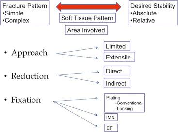
When you feel superior to the material, be warned and remember this quotation from one of the greatest thinkers of our time: “If you can't explain it simply, you don't understand it well enough.” Reflect on the errors in your practice. Associate your failures with disregard for the basic principles of fracture care. Commit yourself to this language and these principles. See the improvement in patient care.
Five things should be gleaned from every injury radiograph. These can be subsumed under the heading of fracture pattern but extend far beyond that simple title. Observational skills vary greatly among those treating fractures. Interestingly, one of the things thought to be associated with expertise is pattern recognition. When you see an expert digest an injury radiograph, you realize how much information is available in the most limited of studies. Seeing these five things should help improve pattern recognition.
First, the fracture pattern is the radiographic representation of the Law of Conservation of Energy. The total amount of energy in an isolated system remains constant over time. This energy is conserved through the accident, but it changes forms. To clarify, there is a significant amount of energy associated with the fractures that we take care of. The representation of the energy is evident by viewing the injury films and the injured part. Specific types of forces create specific types of fractures. Fig. 9.2 is a common picture of fracture mechanics. Without reading the figure legend, draw which fracture pattern is expected from each force. Chapter 6 provides more facts, laws, and specifics. In this chapter, we focus more on why.
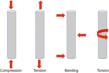
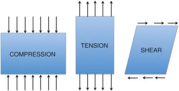
A force is an influence on a structure (e.g., skeleton) that tends to produce motion or deformation. There are a limited number of forces that the skeleton sees. These include compression, tension, and shear ( Fig. 9.3 ). Of note, commonly described forces of bending and torsion are more specific types that can be subsumed under the main categories of compression, tension, and shear. A compressive force is perpendicular and inward relative to the surface of an object. A tensile force is perpendicular and outward relative to the surface of an object. A bending force occurs in many forms (e.g., two-, three-, and four-point and cantilever) and can be “simplified” into tensile and compressive components. The surfaces or molecules in an object subjected to bending are seeing a tensile or compressive force (this fact can be conceptually useful when you are considering which side of an injury is likely to have the purest fracture interdigitation or least damaged soft tissue). A shear force acts parallel or tangential to the surface of an object. A torsion force is a specific type of shear that consists of a twisting or rotation around an axis in an object.
Why does it matter whether you know that a torsional force leads to a spiral fracture pattern? Just associating the deforming force with the pattern provides little. Understanding the character of that pattern provides a great deal. Simple patterns (transverse, oblique, spiral) are typically thought to be consequences of lower energy than their butterfly, comminuted, and segmental counterparts. This lower-energy designation assists with predicting the complication profile and expected outcome when counseling the patient preoperatively.
More importantly, associating the fracture pattern with the amount of absorbed energy helps provide your margin and guide your decision making. The higher the absorbed energy evidenced by the fracture pattern, the lower your margin, and vice versa. What does “margin” mean in this context? Surgery is a controlled form of energy transfer. Energy transfer is cumulative. If you start with a fracture pattern that signifies a large amount of energy, you should realize that the energy imparted via your surgical intervention must be limited and/or delayed. This is not a license for percutaneous malreductions but, rather, a warning shot that signifies potential danger for early invasive intervention. Highly comminuted diaphyseal and metaphyseal fractures demand an atraumatic surgical technique (irrespective of the chosen implant). It is well known at this point that the biologic cost of restoring every single piece to anatomic alignment is not worth the benefit.
Second, the fracture pattern predicts the intrinsic stability of the bone after reduction. This has utility both in deciding whether or not a fracture can be successfully treated conservatively and in understanding the ultimate stability of the construct. This in turn determines the safety of physiologic loading. The specialized vocabulary is increasing, so it is important to unpack new words as we proceed. We should begin with stability, construct, and physiologic load.
Stability has many definitions. As it relates to fracture care principles, stability is defined as the amount of motion between fracture fragments when a construct is placed under physiologic load. A construct is a structure that is built by a combination of implant and bone. A physiologic load is typically felt to be the load experienced by the construct during functional aftercare or motion of a joint rather than weight bearing. To bring this together, the fracture pattern as noted on the injury film clarifies how stable the bone would be on its own after being reduced but before being fixed (i.e., intrinsic stability). Certain fracture patterns are clearly length-unstable even after acceptable reductions (e.g., comminuted pattern). If length restoration and maintenance is important in the care of that fracture, then operative techniques become necessary (i.e., it cannot be treated conservatively). When operative treatment is chosen for an intrinsically unstable pattern, then the type of instability should be clearly defined and the method of fixation should rationally follow. During the treatment period, the implant will be loaded almost exclusively until it can be protected by fracture healing, which creates some intrinsic stability. Fracture care is a race between fracture healing and implant failure. This issue deserves more detailed attention and is covered many more times in this chapter.
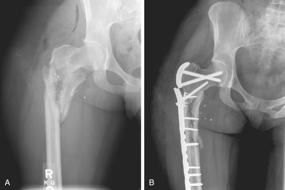
Third, the fracture pattern on injury films characterizes the unbalanced forces in the equation. Newton's third law states that for an object to remain at rest, there must be an equal and opposite reaction for every action. When there is an unbalanced force, an object is not at rest. Think of this in terms of fracture treatment. The surgeon desires to restore anatomy via reduction and to maintain that reduction until fracture healing with an implant (see ). The goal, therefore, is to characterize unbalanced forces and then balance them. Structures obey the laws of nature; therefore the desires of the surgeon must correspond with basic physics. Internal forces and external loads act on fracture fixation constructs. Any fixation construct has a limited number of load cycles before failure. By considering these forces and loads, it is possible to design a fixation construct that minimizes failure potential. To reiterate, unbalanced forces create displacement and subsequent deformity. These forces must be characterized, and the plan for fracture treatment must include specific resistance to them. When this is unclear, the unbalanced forces win. This is why malunion and nonunion radiographs typically resemble the injury films with hardware or implant–bone junction failure ( Fig. 9.4 ).
Fourth, the fracture pattern on the injury films predicts the expected soft tissue injury, both in a general and a specific sense. In a general sense, high-energy fracture patterns are typically associated with high-energy soft tissue patterns. As previously noted, high-energy soft tissue patterns forebode danger when early invasive surgical approaches are chosen. This is why multiple historical publications have shown a higher rate of wound-healing problems and delayed union and nonunion with complex fracture patterns. High-energy radiographs portend more vascular compromise to fracture fragments and skin, thereby naturally leading to longer healing times and more complications.
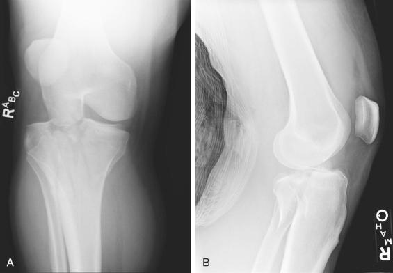
In a specific sense, this pattern recognition becomes even more valuable, especially in areas of the body where fractures and ligamentous injuries are often combined. Let us step up the level of discussion to complex knee injuries. Bicondylar tibial plateau fractures have recently been shown to have variable medial plateau injury patterns. One of the most common medial plateau injury patterns consists of the anteromedial plateau remaining attached to the tibial diaphysis and the posteromedial plateau being separated ( Fig. 9.5 ). The posteromedial plateau is a functional correlate for the posteromedial corner of the knee. The posteromedial corner of the knee is the secondary stabilizer against anterior translation of the tibia (the primary stabilizer being the anterior cruciate ligament [ACL]). It logically follows that when tibial eminence fractures are also present in this fracture pattern (and leave the ACL dysfunctional), the instability pattern is different (the primary and secondary stabilizers now being gone). Look closely at which relationships are maintained on the lateral image. This finding is available on the injury films via pattern recognition and may guide surgical decision making, if noticed.
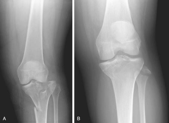
Now consider medial plateau fracture-dislocations in which the lateral plateau maintains continuity with the tibial diaphysis. Although they may fall within the same category, there are broad differentiations. Look closely at Fig. 9.6 . Both are medial plateau fractures. The lateral plateau maintains continuity with the tibial diaphysis in both patterns. This is where the similarities end. The first pattern exhibits lateral condylar widening, centrolateral articular impaction, shortening, and a variable medial plateau fracture pattern. The second pattern exhibits medial plateau articular impaction and varus hinge instability with avulsion of the lateral capsule, lateral collateral ligament, and biceps femoris. These injuries are treated differently. Fracture pattern recognition allows for the prediction of expected soft tissue damage. This can be the difference between success and failure in operative treatment.
Fifth and most important of all, the fracture pattern on injury films defines the expected mode of healing. Ignoring this leads to disastrous consequences for the patient and the surgeon. This important point is elaborated on throughout many other portions of this chapter because it must be considered throughout the flowchart diagram (see Fig. 9.1 ). After all, the goal of operative fracture care is the restoration of function through reduction, fixation, and healing. Without healing, it is impossible to reach this goal.
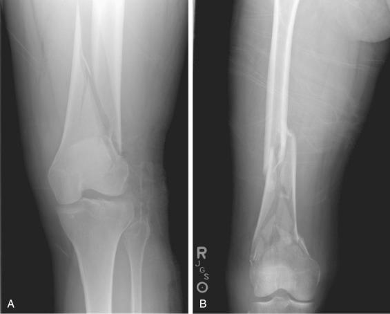
This labyrinth of fracture healing reaches very deep, and Chapter 5 in this volume provides many details about the biology and enhancement of skeletal repair. Let us step away from the details and look at the basic principles of fracture healing through a few examples. Look closely at Fig. 9.7 . The articular fracture patterns can be ignored at this point (we will cover them in more detail in another section, but suffice it to say that every articular fracture pattern should be anatomically reduced, compressed when possible, and heal via primary bone healing). Both injury films reveal supracondylar femur fractures. The metaphyseal fracture patterns are very different. One is a simple oblique fracture pattern, whereas the other is complex (comminuted). How does this affect your operative decision making? To adequately answer this question, we need to cover more vocabulary and get further along the flowchart. Refer back to this question after you finish the “Desired Stability” section of the chapter.
Five things should be gleaned from every injury radiograph:
Fracture pattern = Law of Conservation of Energy
“That pilon fracture pattern appears extremely complex. It is surprising that the surgeon used an extensile approach this early in the injury period. Adding that much additional energy to the injury that early likely factored into the current wound-healing complications that we are seeing.”
The fracture pattern reveals the intrinsic stability of the bone after reduction.
“That tibial fracture pattern is very comminuted. I know that if I choose operative treatment, my implant will be load bearing rather than load sharing. I should be careful with the soft tissue to ensure early healing, which will provide implant protection.”
The fracture pattern characterizes the unbalanced forces that create displacement and subsequent deformity.
“The vertical medial malleolar fracture with medial gutter impaction is the result of compression rather than tension. I wonder why the surgeon attempted to use a tension band construct for fixation. It doesn't seem that it logically balances the unbalanced forces.”
The fracture pattern predicts the expected soft tissue damage.
“This fracture occurred secondary to bending based on the radiographic pattern. Notice how the soft tissue damage reflects the position of the fulcrum. I should be more careful with the soft tissue on that side of the injury. It appears crushed.”
The fracture pattern defines the expected mode of healing.
“The metadiaphyseal comminution demands relative stability. Attempting to achieve absolute stability would require excessive soft tissue stripping in an effort to exact an anatomic reduction.”
You have likely heard the expressions that a fracture is a soft tissue injury with a broken bone inside or that operative fracture care is more like gardening than carpentry work. The underlying message in these expressions is that the soft tissue injury must take precedence over the osseous injury. You cannot effectively and consistently treat fractures while ignoring soft tissue injuries. The most drastic complications of fracture care are typically defined by the soft tissue envelope rather than the fracture itself. So how do you prioritize the soft tissue in fracture care? Consider four ways.
We previously covered the idea that the fracture pattern predicts the expected soft tissue injury. This is a solid general principle to follow, but it does have exceptions (e.g., the transverse fracture with a crush impact injury). It is always necessary to closely evaluate the soft tissue envelope in addition to spending time dissecting the injury films. Soft tissue injury takes different forms: contusions, abrasions, blisters, lacerations, avulsions, degloving (closed and open), and crush. These are all different manifestations of energy transfer. Each affects surgical decision making, with respect to both the timing and placement of operative approaches. Open fracture management is covered in detail in Chapter 18 of this volume. Let us focus on the most commonly used closed fracture classification system.
Fractures with Soft Tissue Injuries is a classic publication from 1984 in which editors Tscherne and Gotzen defined a soft tissue classification of closed fractures that is still referenced today. The key point of the classification scheme is that increased energy levels are represented by higher grades of injury ( Table 9.1 ). These grades of injury provide an understanding of prognosis and guide decision making. Grade 0 closed fractures represent injuries that are caused by indirect violence and reveal negligible soft tissue damage. The corresponding fracture pattern is typically of simple configuration (e.g., torsion fractures in skiers). These injuries can be treated in many ways, and the margin for error is high. Grade I closed fractures represent soft tissue injuries created by fragment pressure from within the soft tissue envelope. The fracture pattern itself is typically mild to moderately severe (e.g., pronation abduction fracture dislocations of the ankle in which the fractured margin of the medial malleolus creates an abrasion or contusion on the medial skin of the ankle). This soft tissue injury must be respected with early reduction of the displacement to limit further soft tissue damage. Any surgical approach in the area of damaged tissue must be done with extra care. A delay in definitive surgical treatment in the injured region may be necessary. Grade II closed fractures represent soft tissue injuries created by direct external pressure or violence. Deep, contaminated abrasions with local skin or muscle contusion are often associated with moderate to severe fracture patterns (e.g., segmental tibial shaft fractures caused by bumper injuries). Impending compartment syndrome must be ruled out or emergently treated if present. These injuries have a high propensity for soft tissue complications and must be treated with the utmost respect. Grade III closed fractures round out the closed fracture classification scheme. The skin is extensively contused or crushed, the muscle damage may be severe, and the fracture configuration is severe (e.g., multifragmentary or comminuted tibial shaft fractures caused by crushing mechanism). Closed fractures that are associated with major vascular injuries, subcutaneous avulsions and degloving, and established compartment syndrome are included in this grade III category. Treatment of these injuries is challenging and may lead to the need for soft tissue coverage procedures. Recognition of this at the beginning is important in setting realistic expectations preoperatively.
| Grade | Soft Tissue Characteristics | Typical Fracture Pattern |
|---|---|---|
| 0 | Minimal damage | Simple |
| I | Caused by bone fragment pressure within soft tissue envelope | Mild to moderate pattern |
| II | Caused by direct external force. Deep abrasions, skin and/or muscle contusion | Moderate to severe pattern |
| III | Crush; extensive skin and/or muscle damage. Vascular injuries, internal degloving, or compartment syndrome | Severe pattern |
Surgical plans are created based on the fracture pattern as recognized through the injury films. Plans should incorporate the desired surgical incision, but a surgical incision is a means to an end in fracture care. The desired ends include visualization of the fracture, preparation of the bone ends, reduction of the fracture, and fixation of the fracture. These ends need to be accomplished in the absence of wound-healing complications. Unfortunately, the desired approach to optimize visualization, reduction, and fixation may not be safely possible. This is where modification of the surgical plan based on the soft tissue pattern becomes necessary. Decisions need to be made by balancing desires with requirements. Every choice comes with a compromise. Choosing where to make incisions requires a familiarity with the zones of blood supply to the skin. Moving away from ideal mechanical locations to stabilize a fracture requires a familiarity with methods to empower a fracture fixation construct. We will cover these issues next.
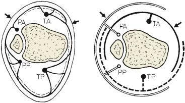
One way to optimize care is by familiarizing yourself with the concept of angiosomes. An angiosome is a composite block of tissue including deep tissue and overlying skin supplied by a named source artery ( Fig. 9.8 ). Comprehensive articles are available in plastic surgery journals that orthopaedic surgeons may not often read. Rather than focusing on comprehensive details, let us review a specific example and see how knowledge of angiosomes may affect surgical decision making.
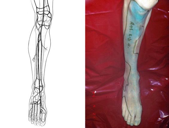
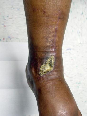
Tibial pilon fractures are complex injuries to treat, primarily because of soft tissue complications. It is an accepted fact that potential soft tissue complications drive surgical decision making. Some of the early results of immediate internal fixation were disastrous. Wound-healing complications and infection led to unacceptable outcomes such as amputation. Some surgeons have chosen to avoid soft tissue complications by limiting surgical incisions. The compromise with this approach is limited access to the articular surface for reduction and the necessity of prolonged external fixator frame duration. Others have moved toward staging surgical treatment (e.g., starting with external fixation to realign the limb while waiting for soft tissue recovery before proceeding with definitive care). This staging has allowed for safer surgical incisions with the benefit of more direct access to the articular surface for reduction. When the decision is made to proceed with definitive internal fixation, care must be taken to choose the optimal surgical approach. The optimal surgical approach is based on the reduction strategy and the mechanics of instability (i.e., consider where you need to be to see, clean, reduce, and stabilize the fracture). This optimal surgical approach should take into account the angiosomes of the ankle and the presence of vascular compromise. This is necessary because soft tissue complications occur even in the presence of staged treatment. It has been shown that a large percentage of tibial pilon fractures are associated with irregular arterial flow. It is logical that making incisions in areas of compromised arterial flow can lead to soft tissue healing problems. Understanding the angiosomes should assist in limiting these complications. In the leg and ankle, large cutaneous vessels arise primarily from the deep fascia around the perimeter of muscles. Most tissues are crossed by two or more angiosomes, receiving supply from each. Junctional zones between angiosomes are the danger areas. The primary junctional zone in the ankle is around the medial face of the tibia. The skin in this area is supplied almost exclusively by the anterior tibial artery ( Fig. 9.9 ). When this artery is compromised, it follows that surgical incisions in this region can be problematic. It just so happens that this is the most likely area for surgical incision breakdown in tibial pilon fracture treatment ( Fig. 9.10 ). Recognizing anterior tibial artery compromise preoperatively could logically mitigate some of these complications.
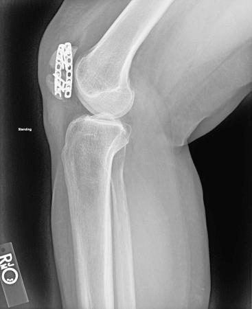
There are times when the soft tissue pattern drives the placement of fixation to less-than-ideal mechanical locations. Let us consider a different scenario. Potential soft tissue compromise comes in different forms. Sometimes it is a direct result of the injury. Other times it is just a consequence of normal anatomy. Consider the patella or the olecranon. Both locations are subcutaneous. Hardware prominence is a documented issue at both sites. Most implants are designed to serve as tension bands in these locations. The concept of a tension band receives more attention under the “Fixation” heading in the flowchart, but let us start with the basics. A tension band is a torque converter applied to the tension surface of an eccentrically loaded bone. To clarify, the implant (whether a wire or plate or suture) must be applied to the tension surface of the bone (the one that sees stretching). The tension surface of the olecranon or the patella is the subcutaneous surface (dorsal for the olecranon, anterior for the patella). Subcutaneous implants are associated with prominence and irritation of the overlying skin. It is tempting to move the implant from the tension surface to one that has more soft tissue coverage (e.g., the medial or lateral surface of the patella or olecranon). Doing so satisfies the desire to limit implant prominence but comes at a cost. The implant is no longer in the correct mechanical position to serve as a tension band. Either the construct must be empowered or the postoperative protocol must be modified (so that the implant sees less load until some healing occurs and it is protected). Failure to do so may lead to construct failure ( Fig. 9.11 ).
Soft tissues must be prioritized in fracture care. Ways to do so include the following:
Recognize the severity of the soft tissue injury preoperatively.
“Fracture blisters are already developing around the ankle. That is a sign that the soft tissue is not ready for an extensile approach and additional surgical trauma.”
Modify surgical plans based on soft tissue injury pattern.
“There is blanching of the skin secondary to fragment displacement in this tongue-type calcaneus fracture. That requires immediate attention and possibly even a very limited surgical exposure, despite the fact that delayed surgical treatment (when soft tissue swelling decreases) is standard.”
Familiarize yourself with the concept of angiosomes.
“ No matter how atraumatic my soft tissue dissection in that area, it is a watershed zone that is already compromised. I better consider alternative surgical exposures instead.”
Empower fracture fixation constructs.
“ The best mechanical position for that implant is clear based on the injury films. Unfortunately, a surgical approach to that area does not allow for joint visualization, and I want to anatomically reduce the articular surface. I think I will compromise the mechanical position of the implant to allow for the benefit of better articular exposure. Next I need to consider how to empower that implant to prevent mechanical failure.”
Refer to the flowchart and review the concepts of “Fracture Pattern” and “Soft Tissue Pattern” as they relate to proactive failure analysis in the system of fracture care. Now we will move to the section of “Area Involved.” To understand this, it is necessary to review the aims of the AO method ( Fig. 9.12 ).
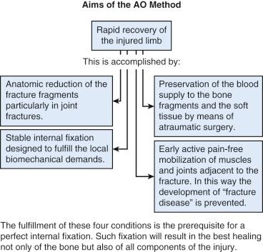
Two important aims of the AO method include (1) the anatomic reduction of the fracture fragments and (2) preservation of the blood supply to the fracture fragments and the soft tissue by means of atraumatic surgery. We should strive to meet these aims while realizing the two create a conflict. We have previously discussed the idea that the quality of a reduction is inversely related to the ability of the surgeon to maintain the blood supply to fracture fragments and soft tissue. To clarify, it is not difficult to enact an anatomic reduction if you remove all the soft tissue from the fracture fragments through a poorly executed extensile exposure; unfortunately, this leaves the fracture fragments avascular and creates healing challenges. Similarly, it is not hard to maintain nearly all the blood supply to fracture fragments and enact a malreduction; unfortunately, the fracture will heal in a nonanatomic position. Neither of these is acceptable. It follows that the compromise should be to enact the quality of reduction required for each specific injury as atraumatically as possible. This means that there is a hierarchy of reduction mandates that should be understood. Thankfully, this hierarchy can be divided into the well-defined segments of the bone, specifically the articular surface (epiphysis), the metaphysis, and the diaphysis. We will cover each one individually and see how the location of the fracture (i.e., area involved) aids in making decisions about fracture care.
The articular surface (epiphysis) mandates an anatomic reduction of all articular fragments. As a general rule, open approaches are generally required to enact an anatomic articular reduction. It is accepted that more damage to the blood supply is likely to occur with the open approach, but the desire is still to limit that as much as possible. The articular cartilage has three functions: (1) to distribute forces evenly, (2) to provide a near-frictionless motion surface, and (3) to serve as a shock absorber during loading. When the articular surface is displaced, it cannot optimally serve these functions. Displacement occurs in two primary forms: (1) articular incongruence and (2) articular malalignment. Articular incongruence is defined as the inability of the joint surfaces to coincide when superimposed. Articular malalignment is defined as an incorrect relationship between the articular surface and the axis of the limb (i.e., rather than the ankle joint surface being perpendicular to the weight-bearing axis and parallel to the floor with loading, it is crooked).
Displacement leads to two primary dysfunctions: (1) point loading and (2) joint instability. One of the few mathematical formulas that is useful in the operating room (OR) is Stress = Force/Area. When joint stress is kept at a reasonable level, the articular cartilage remains healthy. To maintain joint stress at a reasonable level, it is important to distribute the joint forces over large areas. This occurs in an anatomically reduced joint with balanced forces. When the area for force distribution is limited (e.g., a malreduced articular fracture that creates point loading), the stress increases and joint degradation occurs. A simple analogy is watching a lady walk on soft ground with two different types of shoes: a stiletto and a flat. The stiletto concentrates her body weight into a smaller area, increasing the stress and causing her heel to sink into the soft ground. In contrast, the flat would distribute her body weight over a larger area, decreasing the stress and allowing her to walk without sinking. The same thing is occurring at the articular surface level, but instead of sinking, the cartilage in the point-loaded area just degenerates.
Joint instability is defined as the potential for subluxation or dislocation with functional loading. Joint instability occurs from both articular incongruence and joint malalignment. Both cause shear forces and lead to cartilage degeneration. Subtle findings can often be noted on intraoperative radiographs. When the joint space on radiograph is not congruent after reduction, a search for malalignment and/or instability should ensue. If this instability remains, then cartilage loading will continue to be nonanatomic, and the risk for posttraumatic arthrosis should logically increase.
The metaphysis and diaphysis can be taken together because they follow similar principles. The metaphysis and diaphysis do not require anatomic restoration of all fracture fragments to function appropriately; rather, they require the restoration of the relationships between the joint surface and the weight-bearing axis of the limb (alternatively, the restoration of the relationship between the joint above and the joint below the fracture). Because all the fracture fragments do not require perfect anatomic reduction, it is less common to proceed with open extensile approaches to the metaphysis and diaphysis. This will be emphasized and clarified again in the “Reduction” heading of the flowchart.
Once again, the parts of the flowchart (and therefore the fracture fixation system) are interrelated and require some redundancy in thought. Although we have attempted to limit explanation of details and exceptions in favor of simplicity, this is an area where recognizing a few caveats will benefit understanding. Three caveats to not establishing a perfect anatomic reduction of all fragments of a metaphyseal or diaphyseal fracture are (1) when there is simple-pattern metaphyseal/diaphyseal extension of an articular fracture, (2) when the benefits of construct stability provided by an anatomic fracture reduction outweigh the vascular compromise created by increased soft tissue dissection, and (3) when the strain theory is not respected. The first two caveats can be simply explained with examples. The third will be covered in the “Desired Stability” section because it is typically harder to understand and apply.
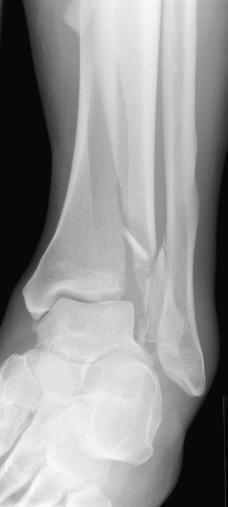
First, when there is a simple-pattern metaphyseal/diaphyseal extension of an articular fracture, this must be anatomically reduced ( Fig. 9.13 ). We previously accepted the statement that the articular surface requires an anatomic reduction to function appropriately. It should become clear that it is impossible to anatomically reduce the articular surface in this fracture without also anatomically reducing the metadiaphyseal extension (the exception being when the cortical extension can bend, allowing an anatomic reduction of the articular surface with a near anatomic reduction of the diaphyseal extension). The articular surface always takes priority and drives the fracture fixation choices.
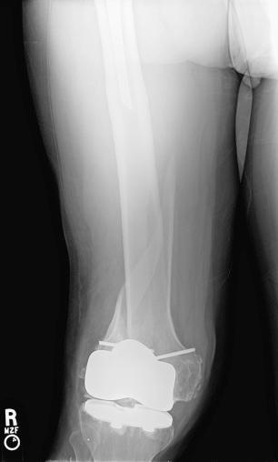
Second, when the benefits of anatomic fracture reduction outweigh the vascular compromise created by increased soft tissue dissection, it is necessary to proceed with a more extensile approach to achieve that anatomic reduction. Try to imagine a situation when this is the case ( Fig. 9.14 ). In this osteoporotic, interprosthetic fracture with limited joint motion above and below the fracture, construct stability is clearly an issue. Choosing a load-bearing construct (through inexact fracture reduction) may work, but the advantages of anatomically reducing the fracture and getting the bone to share the load should be obvious. This is a judgment call, and care must be taken to limit soft tissue dissection and perform atraumatic reduction techniques despite the choice to proceed with a more extensile approach. Dead bone does not heal, even when it is sharing load.
Two important aims of the AO method are as follows:
The anatomic reduction of fracture fragments
Preservation of blood supply to the fracture fragments and soft tissue by means of atraumatic surgery
These two aims create a clear conflict: the quality of a reduction is inversely related to the ability of the surgeon to maintain blood supply to the fracture fragments.
The solution: there is a hierarchy of reduction mandates that is based on the previously well-defined segments of bone: the articular surface, the metaphysis, and the diaphysis.
The articular surface
“That is a complex articular fracture pattern. The benefits of an anatomic reduction of every articular fragment should outweigh the danger of an extensile approach, especially if I respect the soft tissue envelope.”
“It appears that there is diaphyseal extension of that articular fragment. I better consider how I am going to anatomically reduce that in my preoperative planning. Which surgical approach will allow visualization of both the articular surface and the diaphyseal extension?”
The metaphysis and diaphysis
“That is a multifragmentary diaphyseal femur fracture. The benefits of an anatomic reduction of every fracture fragment far outweigh the soft tissue damage that will be created in order to achieve a precise anatomic reduction.”
“This fracture pattern has a complex articular and a complex metadiaphyseal pattern. It is interesting that there are different reduction mandates for those, considering they are similarly complex. It is not just about fracture pattern. The area involved really matters.”
Once again, refer to Fig. 9.1 to orient yourself to the big picture of the system of fracture care. This labyrinth is rich and extremely important to grasp. A misunderstanding here will lead to many treatment failures. First, let us define some new vocabulary. As previously noted, stability has many different definitions; but when it is used in fracture care, the definition is distinct and should be consistent. Stability in fracture care refers to the degree of immobility between fracture fragments when the fracture fixation construct is subjected to physiologic load. Another word used more commonly in everyday language to describe this concept is stiffness. The stiffness of a material is the resistance of that material to deformation. Consider objects likely in front of you currently: a phone and a pen. You might define your pen as more flexible or less stiff than your phone. When you subject them to three-point bending in your hands, there is a clear difference. This is a simple way to conceptualize what we mean when we refer to the stability of a fracture fixation construct. It is important to stop again and define another term. It is important to use the term fracture fixation construct carefully. In orthopaedic fracture care, a construct is defined as a surgeon-built structure that consists of the combination of implant and bone. We must be careful at this point to step back and acknowledge that not all fractures are treated with implants. Conservative care is still acceptable in many situations. In those situations, the construct would consist of the combination of an external stabilizing device (e.g., cast, splint, brace) and bone.
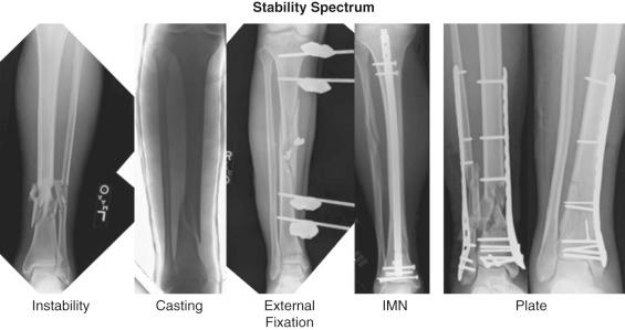
Stability is a spectrum, just like stiffness ( Fig. 9.15 ). On one end of the spectrum is absolute stability. Absolute stability is defined as the absence of motion between fracture fragments under physiologic load (i.e., stiff). On the other end of the spectrum is instability. Instability is defined as an excessive amount of motion between fracture fragments under physiologic load (i.e., flimsy). In between absolute stability and instability is relative stability. Relative stability is defined as controlled motion between fracture fragments under physiologic load (i.e., flexible). The decision between absolute and relative stability is made before the surgical intervention but occasionally must be altered when the desired reduction goals are not being met with the original plan. The decision matters; in fact, it is one of the most important decisions you make in fracture treatment. It matters for two primary reasons: (1) It determines the type and success of fracture healing. (2) It defines the point in time that functional recovery begins.
Let us begin with the type and success of fracture healing. Chapter 5 provides extensive detail regarding the fracture-healing process. Please refer to that chapter to focus on details. Here, we are going to maintain a broad perspective. There are two successful types of fracture healing. Neither of them works well in an area of compromised blood supply. Stated another way, biology is paramount. With biology appropriately prioritized, it is also important to recognize that healing depends on the mechanical environment. Understanding how to manipulate mechanics is necessary. The first type of healing is known as primary bone healing (also called direct bone healing ). This type results from internal remodeling of the bone. It necessitates osteon-to-osteon reduction and functions poorly if at all in the presence of gaps. It requires absolute stability (no motion between fracture fragments under physiologic load). Stated another way, absolute stability leads to primary bone healing and requires an anatomic reduction with compression of adjacent fragments. Absolute stability does not lead to primary bone healing when the reduction is poor. Absolute stability does not lead to primary bone healing when significant gaps are present. Absolute stability does not lead to primary bone healing when adjacent fragments are moving with respect to each other (in fact, this defies the definition). Absolute stability fails in these scenarios.
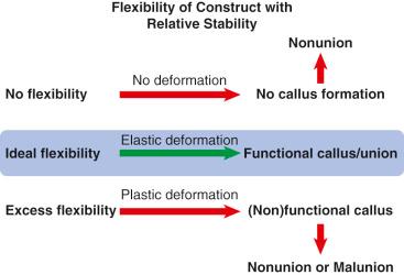
The second type of healing is known as secondary bone healing (also called indirect bone healing ). It is the body's more normal response to injury (i.e., it is what occurs when bone heals in the absence of surgical intervention). It is evidenced by callus formation and requires relative stability (controlled motion between fracture fragments under physiologic load). Stated another way, relative stability leads to secondary bone healing and requires a flexible fixation construct that maintains the reduction but allows motion between fracture fragments. Relative stability does not lead to secondary bone healing when extreme gaps are present or when no motion is occurring between fracture fragments (i.e., stiff construct). Relative stability may not lead to secondary bone healing when excessive motion is occurring between fracture fragments (i.e., flimsy construct). If healing does occur in this situation, it will be in an unacceptable alignment with a loss of the reduction ( Fig. 9.16 ).
The second reason that the choice of stability matters is that it defines the time point when functional recovery can begin. Remember that the goal of fracture treatment (and the AO method) (see Fig. 9.12 ) is rapid recovery of the injured limb through an appropriate reduction, stable fixation, preservation of the blood supply, and early active pain-free mobilization. Both absolute stability and relative stability can accomplish this goal, but instability cannot. As you move toward the extremes of construct flexibility, it becomes harder to mobilize joints. The addition of immobilization after fracture fixation is less than ideal for achieving an early functional recovery.
Stability in fracture care equals the degree of immobility between fracture fragments when the fracture fixation construct is subjected to physiologic load.
Construct equals a surgeon-built structure that consists of the combination of implant and bone
Stability is a spectrum:
Absolute stability—no motion between fracture fragments under physiologic load
Relative stability—controlled motion between fracture fragments under physiologic load
Instability—excessive motion between fracture fragments under physiologic load
The chosen stability matters for two primary reasons:
It defines the type and success of fracture healing.
It defines the point in time that functional recovery begins.
Instability prevents functional recovery.
Remembering the concept of construct stability may lead one to allow for rapid loading of some plated fractures and delayed loading of some rodded fractures.
Now let us focus more on absolute stability by discussing the indications and requirements. You should recognize the clear overlap between the different headings on the flowchart at this point, especially the ones that we have already covered (fracture pattern, soft tissue pattern, and area involved). Absolute stability is indicated for all intraarticular fractures and some metaphyseal and diaphyseal fractures. Regardless of the complexity of an intraarticular fracture pattern, absolute stability and anatomic restoration of all articular fragments are required to reestablish congruence between the two opposing surfaces of the joint. This will serve to distribute forces over the largest area possible, which minimizes joint stress and improves articular cartilage health. Healing of articular fragments with hyaline cartilage occurs best in the presence of anatomic reduction and compression. Rarely, intercalary osteochondral fragments will be missing (e.g., severe open fractures with joint surface loss). This is the only exception to the rule. In this rare scenario, compression of the peripheral articular cartilage fragments may constrain the joint and alter the ability to achieve congruence with the opposing articular surface (i.e., the other side of the joint). Once again, this is a rare and very complicated situation. It requires the maintenance of overall joint surface width and/or depth and eliminates the ability to achieve compression between the peripheral joint surface fragments.
Absolute stability is indicated for some metaphyseal and diaphyseal fractures, but only when the fracture pattern is simple; even then, absolute stability is not always indicated. For example, simple metaphyseal and diaphyseal fracture patterns can often be successfully treated with relative stability. The best example of this scenario is the use of an intramedullary rod to treat a simple-pattern tibial or femoral shaft fracture. By the nature of its mechanics, the intramedullary rod creates relative stability (controlled motion between fracture fragments under physiologic load). Another example of this scenario is the use of a plate to bridge simple-pattern tibial or femoral shaft fractures. Although this is not considered ideal, it can be successful with a clear understanding of construct flexibility.
When is it reasonable to treat simple-pattern metaphyseal and diaphyseal fracture patterns with absolute stability? Let us examine two examples. First, consider a situation in which there is simple-pattern metaphyseal/diaphyseal extension of a simple articular fracture. This must be anatomically reduced and treated with absolute stability to ensure the articular surface reduction is anatomic and remains anatomic until healed. Second, when the benefits of anatomic fracture reduction outweigh the vascular compromise created by increased soft tissue dissection, it is necessary to proceed with a more extensile approach to achieve that anatomic reduction. Consider the interprosthetic fracture with the stiff joint above and below the fracture. The decision can be made to optimize the mechanical environment by anatomically reducing the fracture and compressing it to achieve absolute stability. Here the decision is made to protect the metal by creating a more load-sharing environment. Once again, the biology must be maintained through biologically friendly exposures, atraumatic reduction techniques, and tissue-sparing implant placement. It should be clear that the requirements for absolute stability include an anatomic reduction, interfragmentary compression, and biologic techniques.
Let us look further at what has been called the hallmark of absolute stability, namely, compression. Compression is the act of pressing surfaces together. The primary purpose of compression is to create friction between the opposing surfaces via fracture interdigitation. Remember that the definition of absolute stability is the absence of motion between fracture fragments under physiologic load. As a fracture is subjected to different types of load, the amount of friction between the surfaces of the fragments acts to prevent motion between these surfaces. This friction provides intrinsic stability to the reduced bone and thereby protects the implants by unloading them. This allows the implant to serve more efficiently in a load-sharing environment and win the race between fracture healing and implant failure. An implant in this scenario is less dependent on early fracture healing to protect it from reaching its load-cycle limit and failing.
Compression can be divided into different categories. Let us first consider the difference between axial compression and transaxial compression. In this setting, axial is defined as along the axis of the limb. Ideally, compression is applied perpendicular to the orientation of the fracture. If applied in any direction other than perpendicular, some of the compression is lost to shear (force along the surface of the fracture rather than perpendicular to the surface of the fracture). A simple way to envision this is to consider the concept of a vector. A vector is a geometric entity that has both a magnitude and a direction. A resultant vector can be broken down into its component vectors. The magnitude in this scenario is the amount of force that is being created. The direction is the orientation of application of that force. Look closely at Fig. 9.17 . The force of compression is in a less-than-ideal direction. Because of the orientation of the fracture surfaces, a substantial amount of shear is introduced. When shear is created, it is both inefficient for compression and harmful to the reduction of the fracture (i.e., may displace an anatomically reduced fracture). Following this vector concept, axial compression would be best used when the fracture is nearly perpendicular to the long axis of the bone—a transversely oriented fracture.
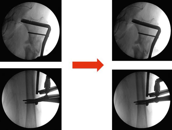
Many different tools and implant design modifications have been created to assist with axial compression. These tools are designed to be used primarily with plate osteosynthesis. They were created primarily to achieve preload. Preload is defined as tensioning an implant and reciprocally compressing the bone or fracture surfaces before the patient actively subjects the implant to load. A logical way to approach this is through an abbreviated review of plate hole design. By understanding how and why the design of plate holes has changed over time, it allows you to reason through methods of axial compression. More time will be spent describing the differences in plate holes later under the “Fixation” section in the flowchart.
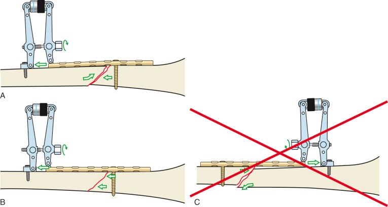
The earliest plate holes were round and slightly larger than the outer diameter of the screw shaft but smaller than the head of the screw. This required screws to be placed perpendicular to the orientation of the hole to fit through and seat into the hole. At this point in history, any compression that could be achieved across a fracture needed to be done outside of the plate itself. For example, compression could be achieved by loading the limb manually or by placing a clamp along the axis of the limb, which does not work very well if you think of clamp application for a transversely oriented fracture. Special plates were designed that contained a compression screw device at the end of the plate (e.g., the Danis coapteur). Alternatively, devices were created that could temporarily attach to a plate to enact compression, then be removed (e.g., the articulated tensioning device; Fig. 9.18B ). Alternative options included using the universal distractor in compression (see Fig. 9.18E ) or using a Verbrugge clamp attached to a single hole in the plate and a screw outside of the plate (see Fig. 9.18G ). Because every choice necessarily comes with a compromise, design continued to evolve. The compromises made with each of the previously listed devices were increased surgical exposure, equipment, and surgical time. This led to the development of a modified plate hole that allowed for compression with the plate–screw relationship alone (i.e., no longer requiring an additional device). It seems that two plate holes were being simultaneously designed to function in this manner. The first was present on the Bagby plate. The second was present on the AO plate and became known as the dynamic compression unit (DCU). It was found on a plate termed the dynamic compression plate (DCP). It consisted of an oblong hole, which was the combination of an inclined and transverse cylinder ( Fig. 9.19 ). The plate was first attached to one side of the fracture with a screw. A screw hole on the other side of the fracture was then drilled eccentrically in the plate hole (i.e., toward the side of the hole farthest away from the fracture). As the screw head engaged the plate hole, it began to move horizontally down the transverse cylinder. This movement created a compressive force between the fracture ends by moving one relative to the other (more on this in the “Fixation” section under “Compression Plating”). The advantage of this plate hole design modification is that compression no longer required additional devices, exposure, or time. The disadvantage was that the compression that could be achieved was limited compared with the previously used devices. Remember that these devices and design modifications were most optimally used in transverse fracture patterns that were perpendicular to the long axis of the bone (i.e., axial compression), but fracture patterns vary, and compression must be more generalizable to different patterns. These devices and plate hole modifications can be used in oblique fracture pattern variants, assuming the plate can be attached such that it creates an axilla to prevent shear from creating deformity. An axilla, when used in the context of plating constructs, is an acute angle created between the plate and the oblique surface of the fracture. Review Fig. 9.20 without reading the figure legend and apply the concept of a vector. Both fracture patterns are oblique. Both see the same compressive vector. Both see shear because the direction of compression is not perpendicular to the fracture surface. Which one works? It should be becoming clear that both the orientation of the fracture line and the possible position of the implant (i.e., what anatomic surface the implant can be placed onto safely) will determine the type of compression that you choose.
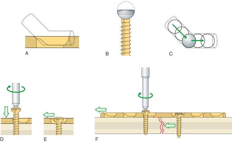
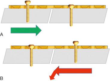
Transaxial compression differs from axial compression in that the direction of the compressive force applied is across or more perpendicular to the long axis of the limb. The simplest form of transaxial compression is the lag screw. This is somewhat of a misnomer because any type of screw can accomplish the lag principle. It is first and foremost a technique. That stated, some screws have been designed specifically to lag. The lag principle states that a screw thread must not engage the near cortex but must engage the far cortex. To simplify, a hole that is larger than the outer diameter of the screw is drilled in the near cortex and the medullary bone until reaching the fracture site. The remaining medullary bone and the far cortex are drilled with a different drill bit to create a hole that is smaller than the outer diameter of the screw (typically the same diameter as the core of the screw). This creates a glide hole in which the screw has no purchase and a thread hole in which the screw gains optimal purchase. As the head of the screw impacts the near cortex (or plate that it is placed through), it acts as a torque converter, converting the torque energy created by the operator's rotating hand into compression at the fracture site ( Fig. 9.21 ). Careful preoperative planning allows the screw to be placed in an atraumatic fashion with minimal soft tissue/vascular compromise. Of note, the screw should be placed near the center of the fragment to prevent propagation of the fracture line into the drill hole (this may need to be modified if more than one lag screw is being used). Additionally, it should be placed perpendicular to the fracture itself such that it creates pure compression through the direction of the vector.
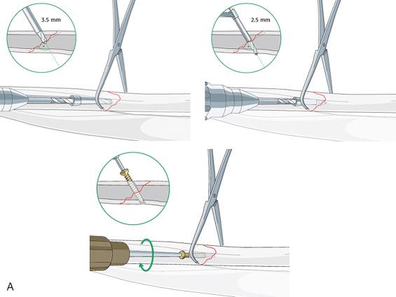
Rarely, lag screws can be placed as the sole fixation. This is indicated only when the fracture sees minimal load and the fracture length is at least twice the diameter of the bone at the fracture center. In this rare scenario, the lag screws must be carefully positioned such that more than one can be placed. Even in this case, it is important to consider the stability afforded by the screws alone. The lag screw is compromised by the limited lever arm with which it works. This lever arm is often too small to resist functional loads of bending and shear. In addition, it provides no factor of safety. If the lag screw loosens, there is little else to prevent displacement of the fracture fragments. To complicate things further, the obliquity of the fracture line is rarely parallel to the long axis of the bone; hence, the perfect position of the lag screw is rarely perpendicular to the long axis of the bone. As the bone is loaded axially, shearing occurs along the obliquity. Screws placed perpendicular to the long axis of the bone are in a better orientation to resist shear (but rarely in the correct orientation to provide pure compression across a fracture). Because of these reasons, the lag screw should almost always be protected by a plate (the mechanical function of which is termed a neutralization plate or protection plate ). This will be covered further under the “Fixation” section of the flowchart.
Another form of transaxial compression occurs when a plate is first attached to the acute angle of an oblique fracture. In this scenario, attempting to create compression along the axis of the bone will lead to uncontrolled shear and displacement of the reduction. This is commonly necessary in the proximal femur but can be used in other areas of the skeleton as well. Review Fig. 9.17 once again. In this example, it was necessary to attach the plate first to the acute angle of the fracture (because of the design of the implant itself). Attempting to create compression along the axis of the bone with an articulated tensioning device led to shear, which created shortening and medial translation of the distal segment along the plane of the fracture. Recognizing this problem led to the decision to place a conventional screw through the plate distal to the fracture. This conventional screw application created compression across the axis of the fracture (transaxial) by pulling the distal fragment toward the plate, thereby compressing the distal side of the oblique fracture to the proximal side.
To review, compression can be divided into different categories. We have just distinguished axial compression from transaxial compression and described the different tools and techniques used with each. Now let us differentiate between static compression and dynamic compression. Static compression is that which is applied at the time of the surgical intervention. Once applied, it remains virtually unaltered (in reality, it decreases over time because the law of entropy states that all systems in the universe move from a position of order to one of disorder). Examples of static compression include all the axial and transaxial compression scenarios that we have previously discussed. Dynamic compression differs from static compression in that postoperative functional use of the limb leads to periodic partial loading and unloading. Stated another way, the fracture fragments are not only compressed by the preload of the implant (static) but also subjected to additional compression, which results from harnessing forces generated at the level of the fracture when the skeleton comes under physiologic load. This is not to be confused with the DCU or DCP, both of which were designed to produce static compression. An example of dynamic compression is the tension band concept. This is covered in more detail in the “Fixation” section.
In summary, absolute stability is the absence of motion between fracture fragments when subjected to physiologic load. It is always indicated for articular fractures, regardless of the fracture pattern. It is almost never indicated for complex metaphyseal and diaphyseal fracture patterns (because the compromise to the blood supply required to enact the anatomic reduction of every small fragment outweighs the advantage of anatomically reducing each piece). It is occasionally indicated for simple-pattern metaphyseal and diaphyseal fracture patterns. It requires the perfect restoration of all loaded fracture fragments back into anatomic position. It achieves load sharing through compression of fracture surfaces that interdigitate and increase friction at the fracture site. The compression can be achieved through axial or transaxial means. It leads to primary bone healing when done correctly. This necessitates biologically friendly surgical approaches, reduction techniques, and implant placement, which can be difficult.
Absolute stability—no motion between fracture fragments under physiologic load
Always indicated for articular fractures, regardless of the complexity of the pattern
Almost never indicated for complex metaphyseal and diaphyseal fracture patterns
Occasionally indicated for simple-pattern metaphyseal and diaphyseal fractures
Requires the perfect restoration of all loaded fracture fragments back into anatomic position
Achieves load sharing through compression of fracture surfaces that interdigitate and increase friction at the fracture site
Compression is the hallmark and can be achieved either axially or transaxially.
Leads to primary bone healing
Necessitates biologically friendly surgical approaches, reduction techniques, and implant placement
“I would like to achieve absolute stability of this tibial shaft fracture, but I am concerned that complexity of the fracture pattern will lead me to damage the blood supply to the fragments too much while trying to obtain an anatomic reduction.”
“That ulnar shaft fracture orientation is transverse. I would love to use a lag screw, but I don't see how that would be possible. I better choose an axial compression technique instead.”
At this point, let us shift our attention away from absolute stability and toward relative stability. Once again this is a decision that is made before surgery. Relative stability is defined as the controlled motion of fracture fragments under physiologic loading conditions. Indications for relative stability include most metaphyseal and diaphyseal fractures (excluding the two previously covered caveats). Epiphyseal or articular fractures are never appropriate for relative stability. Complex fracture patterns are ideal for relative stability. Simple fracture patterns are amenable to relative stability but are less than ideal for relative stability. Think for a moment why this would be the case. Remember why choosing the correct type of stability matters. It matters for two primary reasons: (1) It determines the type and success of fracture healing, and (2) it defines the time point that functional recovery can begin. Let us focus on determining how the type (not location) of fracture pattern and the choice of stability are intrinsically linked. This teeters on two important concepts: (1) strain and (2) stress concentration versus stress distribution. Let us start with the one that is the most challenging to grasp, namely, strain.
In 1977, Perren and Cordey penned a manuscript in German that first described an interpretation of mechanical influences on tissue differentiation. This became known as the Strain Theory of Perren. In 1980 a second manuscript by the same authors was published in English. Within this manuscript, Perren wrote: “These thoughts about the mechanical influences on tissue differentiation are not intended as conclusive evidence because precise data are still not available, but we hope that they will stimulate thought and provide a basis for discussion.” More than 30 years later, these thoughts are still stimulating discussion and research on cell mechanotransduction. As importantly, this theory is still being manipulated in operative theaters all around the world in an attempt to more consistently achieve fracture healing. Let us consider how to apply this theory in a practical manner in surgery.
In physics, strain is a magnitude of deformation. It is the change in the dimension of a deformed object during loading divided by its original dimension. When translated to fracture care, it is equal to the change in length (or distance) between fracture fragments during loading divided by the original (before loading) length (or distance) between fracture fragments.
Most of you reading this chapter are not mechanical engineers or physics wizards. In light of that, just for a moment, I would like to trade perfect accuracy of mechanical terms for understanding. Stated the most useful way in terms of fracture care, strain is the motion that occurs between fracture fragments during loading divided by the resting distance between the same fracture fragments after fixation.
This is a formula that we all can work with. You really only need to remember this formula and one detail to be able to manipulate strain to your advantage in the operating room. The detail is that a low-strain environment leads to bone formation (i.e., healing). You already know that primary bone healing occurs in the absence of motion (absolute stability), and secondary bone healing occurs with controlled motion (relative stability). Let us take some time to consider three different scenarios to see how this works.
In scenario 1 ( Fig. 9.22A ), we have a complex metadiaphyseal fracture pattern. We know that a complex metadiaphyseal fracture pattern is an indication for relative stability and that relative stability provides controlled motion of fracture fragments under physiologic load. We know that restoring the relationship between the joint surface and the diaphysis is all that is necessary. Stated another way, reducing every single fracture fragment anatomically would be both unnecessary and counterproductive (i.e., it would require excessive soft tissue stripping and thereby lead to avascular fragments). Restoring length, alignment, and rotation rather than the perfect anatomic restoration of every fragment is preferred. We know that this can be accomplished with many different types of implants. Let us refer to the formula:
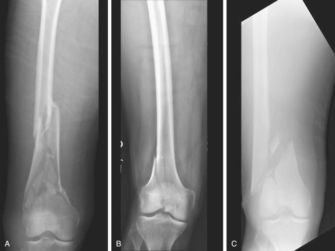
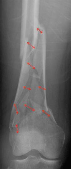
The total resting distance between all fracture fragments is a large number (as it always is with comminuted, multifragmentary fractures because of the cumulative distance between so many different fragments, see Fig. 9.23 for a visual illustration of this). When a large number is in the denominator of a fraction, then the overall value is likely to be a low number (because it is impossible to create so much motion that the numerator will be high enough to make the overall value high); therefore the strain is likely to be low. Low strain leads to bone healing. It is hard to lose in this scenario. This is one of the easiest fracture patterns to treat successfully, despite the fact that it is broken into many pieces.
In scenario 2 (see Fig. 9.22B ), we have a simple articular fracture pattern. We know that any type of articular fracture pattern is an indication for absolute stability and that absolute stability is defined as no motion between fracture fragments under physiologic load. Anatomic restoration of the fracture fragments is required. Interfragmentary compression is important. Let us refer to the formula:
The total resting distance between fracture fragments is going to be very low (because the two fragments are compressed together in anatomic position, and thus the distance between them is miniscule). That means the denominator is small. Reaching a low strain in this scenario requires us to strive for a very low numerator and allow virtually no motion between fragments. Thankfully, that is what absolute stability provides. Using absolute stability for the treatment of simple fracture patterns requires the surgical skill to anatomically reduce the fracture with a biologically friendly technique. Assuming you possess it that day, it is hard to lose in this scenario.
In scenario 3 (see Fig. 9.22C ), we have a simple metaphyseal fracture pattern. We know that metaphyseal fracture patterns do not have to be anatomically reduced like articular fractures. All that is required from a reduction standpoint is the restoration of the relationship between the articular surface and the diaphysis. We are left with a choice. Do we choose absolute stability and anatomically reduce the simple metaphyseal fracture pattern? If we make that choice, we know that we can reach a low strain environment and achieve primary bone healing just as we did in scenario 2. Or, do we choose relative stability instead because perfect restoration of all fragments is not required? Certainly, that is a temptation because it would allow us to do less soft tissue dissection and take a more biologically friendly surgical approach. This is where it gets interesting. Let us refer to the formula:
If we choose relative stability and accept a near-anatomic (but imperfect) reduction, then the distance between fracture fragments (and therefore the denominator) is low. We have already stated that when the denominator is a small value, then to reach a low strain, the motion (numerator) with loading must be very small, almost nonexistent. Unfortunately, if we create a stiff construct and reach that small numerator, then we cannot achieve primary bone healing (because the fracture fragments are gapped so direct remodeling cannot occur). But we know that secondary bone healing requires a certain amount of flexibility to induce callus formation (remember that relative stability is defined as controlled motion between fracture fragments under physiologic loading, not lack of motion). This controlled motion is not optional. It is necessary. Tissue differentiation into callus formation (bone healing) will not occur without it. We have a problem. Based on the strain theory and a previous publication by Perren, one option is to create a malreduction to increase the size of the denominator. This is less than ideal because our goal of fracture care is to restore both form and function. The other solution flies in the face of the strain theory but can work. In this solution, we can keep the gap width small and make the construct more flexible to achieve enough motion to induce callus formation. You should recognize that even though this can work, it does not fit well into the strain theory formula because the strain is actually a higher number. This is where the theory breaks down and has come into question.
Remember it is a theory, and although important, it still has holes. How much motion is enough to induce callus but not too much (such that fibrous tissue is formed)? How do we successfully treat simple-pattern femoral and tibial diaphyseal fractures with relative stability through intramedullary rodding? Although it is important to understand the strain theory and apply it intraoperatively, it is also important to realize that we are making macromanipulations in an attempt to influence the microscopic environment without a clear gauge to tell us when we are correct. This is akin to measuring in millimeters, marking with chalk, and cutting with an axe. The attempt is important, but it is still imperfect.
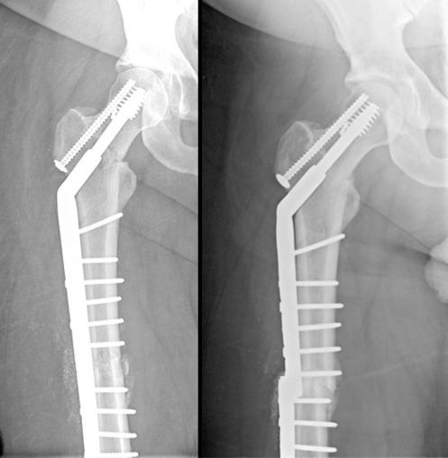
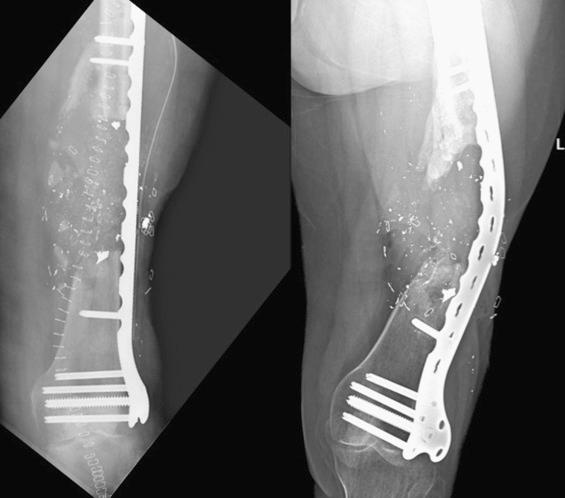
Let us move to a topic that is much easier to understand and explain. Although strain is mainly concerned with the fracture site (motion and distance), stress distribution versus concentration is mainly concerned with the implant. This is best described with an analogy. Pick up a pen or pencil and subject it to three-point bending. First do it by putting your thumbs together in the middle of the pen and your hands toward the ends of the pen. Bending the pen in this manner concentrates or focuses stress on the small section of the pen between your thumbs. It is likely that if you tried hard enough, you could break the pen by concentrating stress on that small area between your thumbs. Now take the pen and place your thumbs toward the periphery (close to the rest of your hands) and bend it again. Bending the pen in this manner distributes or apportions or shares the stress over the length of the pen between your two thumbs. It is likely that you can see a bowing of the pen. It will be much harder to break it in this manner because the stress is being distributed over such a large distance. Now imagine that your pen is a bone and your thumbs represent screws that you place intraoperatively either near to or far away from the fracture. When screws are placed close to each side of a fracture, this concentrates stress on the plate. The plate has natural stress risers in the form of screw holes. This is where an implant typically fails when loaded in bending in this manner ( Fig. 9.24 ). That is not to say that an implant cannot fail when stress is distributed over a larger area ( Fig. 9.25 ). This is just a much more infrequent scenario. We should strive intraoperatively to distribute stress rather than concentrate it whenever possible.
In summary, relative stability is defined as the controlled motion of fracture fragments under physiologic load. It is never indicated for articular fractures. It is indicated for all complex metaphyseal and diaphyseal fracture patterns, and some simple-pattern metaphyseal and diaphyseal fracture patterns. It does not require the perfect restoration of all fracture fragments back into anatomic position. It does require a restoration of the relationships between the joint above and the joint below the fracture. It leads to secondary bone healing when done correctly. This necessitates an understanding of the Strain Theory of Perren as well as the concept of stress distribution versus stress concentration. Remember that motion is necessary for secondary bone formation and therefore for fracture healing when relative stability is chosen. Refer to Fig. 9.16 to review the graphic depiction of how variations in flexibility affect the ability of the surgeon to be successful when using relative stability.
Relative stability—controlled motion between fracture fragments under physiologic load
Never indicated for articular fractures
Indicated for all complex metaphyseal and diaphyseal fracture patterns
Indicated for some simple-pattern metaphyseal and diaphyseal patterns
Does not require the perfect restoration of all fracture fragments back into anatomic position
Does require the perfect restoration of relationships between the joint above and the joint below the fracture
Leads to secondary bone healing when done correctly
Necessitates an understanding of the Strain Theory of Perren
Strain = Magnitude of displacement between fragments during loading/Total resting distance between fragments after stabilization
Low-strain environments lead to bone formation.
Complex metadiaphyseal fracture pattern treated with relative stability (either with plate or rod or external fixator)
The total resting distance between all fracture fragments is large (denominator).
Strain is therefore likely to be a low number because the denominator is large.
Low strain leads to bone formation through secondary bone healing.
Simple articular fracture pattern treated with absolute stability (lag screws)
The total resting distance between fracture fragments is small (denominator).
With a small denominator, the numerator must be small to achieve a low-strain environment for bone healing.
Absolute stability by definition is no motion between anatomically reduced fracture fragments under physiologic load; hence, the numerator is small.
Low strain leads to bone formation through primary bone healing.
Simple metaphyeal fracture pattern = DANGER
Metaphyseal fracture patterns do not have to be anatomically reduced like articular fractures (i.e., each piece does not have to be perfectly restored; rather, just the relationships between the joint above and below must be anatomically restored).
Minimally invasive osteosynthesis is gaining popularity, leading to the desire to not see the fracture.
This temptation to do less soft tissue dissection and bridge plate or place rods across simple fracture patterns is where things get interesting.
Choosing relative stability and accepting an imperfect reduction leads to a small resting distance between fragments after stabilization (denominator).
This means the magnitude of displacement between fragments during loading must be small (numerator) to achieve a low-strain environment for bone healing.
PROBLEM: Primary bone healing cannot occur across reduction gaps; secondary bone healing cannot occur without motion.
SOLUTIONS: Anatomically reduce the fracture and achieve absolute stability and primary bone healing.
Accept the imperfect reduction (still maintaining restoration of the relationship between the joint above and below as a minimal standard), and make the construct more flexible to induce callus formation (this flies in the face of the strain theory but can work).
Necessitates an understanding of the concept of stress distribution versus stress concentration
Primarily concerned with the implant when considering fracture healing
Bending the pencil analogy—the screws closest to the fracture are your thumbs.
Stress distribution is mechanically favorable.
Motion is necessary for secondary bone healing.
“That metaphyseal distal tibial fracture has a simple oblique fracture pattern. If I am going to choose relative stability and plating, I better consider how to ensure there will be enough motion to induce callus formation.”
“Those postoperative radiographs show a nonanatomic reduction of a simple-pattern fracture that was fixed with locking screws right next to each side of the fracture. Some would call that a nonunion machine. The fracture is not well enough apposed to allow for primary bone healing, and the construct is not flexible enough to induce callus.”
The approach portion of the flowchart includes two primary topics. The first is intraoperative positioning. The second is the actual surgical exposure. Covering the exposure without the positioning leaves out a key portion of the surgical procedure. It is this portion that defines which exposures are even possible. It is this same portion that defines the relationship of gravity to the fracture reduction. Just as important, this portion confers risk from the outset to the patient's physiologic status and pressure-/stretch-sensitive areas. Let us start with intraoperative positioning.
The goal of surgical positioning is to provide access to the proposed surgical site(s) while preventing position-related complications. Positioning must also take into account any planned intra-operative imaging needs (see ). All perioperative team members are responsible for patient safety through shared decision making and teamwork. Attention during this portion of the procedure is not just important for ensuring ideal access to the fracture. It is also important in preventing surgical-related claims. The three most common intraoperative positions used in orthopaedic trauma care include the supine position, the prone position, and the lateral position. The most common complications associated with intraoperative positioning include pressure ulcers and peripheral neuropathies. General principles are applied no matter which position the patient is placed in. These include an awareness of all joint positions in space, as well as the application of padding materials around point-pressure areas to distribute local tissue pressures over a broader area to prevent skin necrosis. Care should be taken to ensure no skin-to-metal contact to prevent possible burns when electrocautery is used. Rarer and more severe complications include vascular-related events such as acute compartment syndrome and cortical blindness. Risk factors that are thought to predispose patients to positioning-related complications have been identified and are listed in Box 9.1 . It should be mentioned that although one of the primary goals in careful placement of padding and positioning of patients’ extremities is aimed at the mitigation of postoperative neuropathies, not all postoperative neuropathies are position-related. Literature suggests that not all postoperative neuropathies have mechanical causes. It seems that a certain proportion are instead attributable to inflammatory or infectious etiologies, becoming clinically evident through the relative immunocompromised state that a surgical procedure can induce.
Diabetes mellitus
Peripheral vascular disease
End-stage renal disease
Malnutrition
Advanced age
Immune system compromise
Preexisting contractures
Cachexia
Obesity
Problems with regulation of body temperature
Prolonged surgical times
It is good practice to employ preoperative plans and/or checklists during a presurgical time-out to ensure repositioning of the patient's head and extremities (when feasible) if prolonged surgical times are expected (longer than 2.5 to 3 hours). This includes specifying at what time point the repositioning is to be performed and specifically by which member of the perioperative team.
The next few sections consider the three most common positions individually and focus on common complications and safety-related measures to prevent them.
The goal is to provide access to the proposed surgical site(s) while preventing position-related complications.
When choosing the optimal patient positioning, be cognizant of the relationship of gravity to the fracture reduction.
The most common complications associated with positioning are as follows:
Pressure ulceration
Peripheral neuropathies
Be aware of risk factors that predispose to position-related complications (see Box 9.1 ).
Use preoperative checklists to ensure patient repositioning for long cases.
General recommendations regardless of specific position used include the following:
Anatomic spine alignment
Pressure-reducing materials and interval repositioning in prolonged procedures
Limiting arm abduction less than 90 degrees
Preventing shoulder and elbow hyperextension
Padded arm boards at the same level as table height
Limiting contralateral head rotation
“I operated on his tibia, but postoperative complaints were centered around numbness in the ulnar part of his hand. I'm not sure about arm position during the surgery. I really didn't pay attention before draping.”
The supine position is the most common position for operative fracture care. It is the optimal position for addressing airway patency, gas exchange, and vascular access problems. It places common lines, tubes, and drains in standard orientation. Gravity is directed toward the dorsal recumbent portions of the patient, and the pressure points are the dorsal osseous prominences. Stretch points are apex anterior. The most cranial pressure point is the occiput ( Table 9.2 ), and postoperative alopecia is most commonly preceded by localized swelling and pain in this area in the immediate postoperative period. Pressure-reducing materials and pressure repositioning are recommended for prolonged procedures. Notifying the anesthesiologist when prolonged operative times are expected and periodic assessment as needed may help decrease the incidence of this problem. Cranial stretch points include the cervical spine (see Table 9.2 ), and anatomic alignment should be maintained while protecting the occiput.
| Position | Supine | Prone | Lateral Decubitus |
|---|---|---|---|
| Pressure points | Doral osseous prominences
|
Anterior osseous prominences
|
Lateral (down side) prominences
|
| Stretch points | Apex anterior
|
Apex posterior
|
Apex lateral (up side)
|
Moving caudally, arm position is next, with pressure points noted in the scapular and thoracic vertebrae (in cachectic patients) and olecranon/cubital tunnel area. Stretch points are noted primarily at the brachial plexus and antecubital fossa (see Table 9.2 ). Current recommendations include limiting arm abduction to less than 90 degrees and preventing both shoulder and elbow hyperextension. The use of appropriately padded arm boards at the same level as the table height limits brachial plexus stretch. Limiting contralateral head rotation is also recommended for the same reason. Forearm position should be supination or neutral to decrease pressure on the ulnar nerve. If the decision is made to tuck the arms at the side, then the forearm should remain in neutral position with care to protect against pressure to the ulnar nerve.
Lower extremity pressure points include the sacrum, ischial tuberosities, fibular heads, and calcanei (see Table 9.2 ). Padding is recommended if pressure is noted around the fibular head. Any semicircumferential restraints (such as restraint belts) should be placed while being mindful of anterior pressure points (e.g., anterior superior iliac spine and lateral femoral cutaneous nerve, fibular head and common peroneal nerve). In the supine position with the legs supported, stretch points only occur with hip or knee flexion contractures. In these instances, it is recommended to prevent stretch past what is comfortable preoperatively to limit the risk of femoral and sciatic neuropathy.
Optimal for addressing airway patency, gas exchange, and vascular access and for placing common lines, tubes, and drains in standard orientation
Be mindful of anterior pressure points created by supports such as restraint belts (anterior superior iliac spines and lateral femoral cutaneous nerve) and wraps (fibular head and common peroneal nerve).
Pressure and stretch points—see Table 9.2 .
General recommendations specific to the supine position are as follows:
Supination or neutral forearm position (ulnar nerve)
Padding around fibular head and calcanei
Review flexion contractures, and consider how these affect pressure and stretch.
“My patient came back to his 6-week follow-up visit complaining of occipital alopecia. I think I remember him complaining of swelling in that area of his head postoperatively. I really need to start communicating better with anesthesia when prolonged procedures are expected, to ensure that repositioning is systematized.”
The prone position provides dorsal access and logically reverses the common pressure points and direction of stretch. It is the most limiting with respect to airway patency, gas exchange, and vascular access problems; therefore it requires a pause point preoperatively to ensure the trauma patient can be safely placed in this position. Cranial pressure points primarily include the face, eyes, and chin (see Table 9.2 ). Cervical alignment should be maintained while protecting these areas and the endotracheal tube. Increased facial and airway edema is seen when the head is positioned below the level of the heart.
The chest, abdomen, and pelvis are suspended from the table with rolls that extend from the anterior shoulder area to the iliac crests. This suspension allows for chest wall excursion, decreases intraabdominal pressure, and minimizes venous congestion. Morbid obesity and macromastia create special challenges for pressure relief. Care should be taken to avoid excessive pressure on the anterior clavicle, areolar, anterior superior iliac spine, and femoral nerve areas. When placed in anatomic alignment, the spine will reveal the normal cervical and lumbar lordosis and thoracic kyphosis with respect to the tabletop.
The arms should be placed at less than 90 degrees of abduction with slight forward flexion of the shoulders, with the elbows flexed to 90 degrees or less and the forearms pronated. Shoulder abduction greater than 90 degrees is felt to increase the risk of stretching the plexus across the coracoid process and glenohumeral joint; alternatively, some prefer tucking and padding the arms at the side in the prone position. Adequate padding should be applied under the elbows. Below the waist, pressure points include the patella and dorsal surface of the foot (see Table 9.2 ). Pressure-relieving positioning aids, such as gel donuts and rolls, are recommended. Genitalia should be allowed to hang freely. Of particular importance in the obese population, care should be taken to ensure there are no redundant skin folds trapped underneath the patient.
Most limiting position with respect to airway patency, gas exchange, and vascular access problems
Pressure and stretch points—see Table 9.2 .
General recommendations specific to the prone position are as follows:
Suspension of chest, abdomen, and pelvis from the table with rolls that extend from the anterior shoulder area to the iliac crests—allows for chest wall excursion and decreases intraabdominal pressure
Special care in morbid obesity and macromastia
The lateral decubitus (also called lateral recumbent ) position provides access to both anterior and posterior structures in a single surgical position, often at the cost of compromising ideal access to both. The position is typically named by the down side (e.g., right lateral decubitus position consists of the right side being dependent and the left facing upward). The lateral aspect of the dependent side is primarily at risk of pressure ulceration, whereas the nondependent side risks traction injuries (see Table 9.2 ).
Starting cranially, the lateral aspect of the face and the ear are at risk. Pressure must be limited in these areas while maintaining horizontal cervical alignment to the bed. A chest roll should be placed distal to the axilla to elevate the shoulder from the bed, relieve pressure on the dependent arm, allow chest motion with respiration, and minimize excessive shoulder circumduction to prevent stretch on the suprascapular nerve. The misnomer of axillary roll can be dangerous when formal teaching is not provided to ensure the correct position of this roll is accomplished. Placing the roll in the axilla theoretically increases the potential for compression-induced brachial plexopathies postoperatively. The arm is positioned in front of the patient with the elbow flexed (hand toward face) or extended. Flexion of the elbow provides the advantages of moving the dependent arm farther away from the radiographic field on elbow procedures, but hyperflexion should be avoided to prevent stretching of the ulnar nerve in the cubital tunnel. The forearm is placed in neutral or supinated position. The nondependent arm is suspended on a positioning device or pillow in a relaxed position. Lateral position is maintained through the use of a beanbag or alternative lateral positioning device. The dependent lower extremity is flexed slightly at the hip and knee (to protect the femoral and sciatic nerves, respectively) with padding beneath the fibular head for protection of the peroneal nerve and beneath the lateral malleolus for ulcer prevention. A positioning device or pillow should be placed between the legs to relieve pressure and maintain neutral adduction.
Named by the down side (i.e., left lateral decubitus is left side down)
Lateral aspect of dependent side is primarily at risk of pressure ulceration, whereas the nondependent side risks traction injuries
Pressure and stretch points—see Table 9.2 .
General recommendations specific to the lateral decubitus position are as follows:
Chest roll placed caudal to axilla
Arm positioned in front of patient (elbow can be flexed or extended) and the forearm neutral or supinated
Nondependent arm suspended on positioning device or pillow in relaxed position
Dependent lower extremity flexed slightly at the hip and knee
Padding beneath the dependent fibular head and lateral malleolus
Positioning device to maintain lateral position (e.g., beanbag or lateral positioning aid)
Positioning device or pillow between the legs to relieve pressure and maintain neutral adduction
The hemilithotomy position is sometimes used to improve radiographic visualization for lower extremity procedures by flexing the nonoperative hip out of the way of the fluoroscopy beam. Unique risks in this position include compartment syndrome, femoral nerve compression beneath the inguinal ligament (controversial), and peroneal nerve compression at the fibular head against the well-leg holder. If this position is chosen, care should be taken to carefully position the extremity, limit hip flexion and abduction, choose well-leg holders that focus pressure toward the foot and ankle region rather than the popliteal fossa region, and relieve pressure around the fibular head.
Become a Clinical Tree membership for Full access and enjoy Unlimited articles
If you are a member. Log in here