Physical Address
304 North Cardinal St.
Dorchester Center, MA 02124
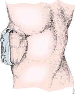
The external fixator was invented 12 years before the plaster cast. In 1846 Jean Francois Malgaigne devised an ingenious mechanism consisting of a clamp that approximated four transcutaneous metal prongs to reduce and maintain patellar fractures ( Fig. 8.1 ). In the 170 years since Malgaigne's invention, many other external fixation systems have been introduced. Among the best known are the Parkhill bone clamp (1897), Lambotte's monolateral external fixator (1902), Roger Anderson's 1934 fixation system, the 1937 Stader apparatus—originally developed for managing fractures in large dogs —and the external fixator of Swiss physician Raoul Hoffmann (1938) ( Fig. 8.2 ).
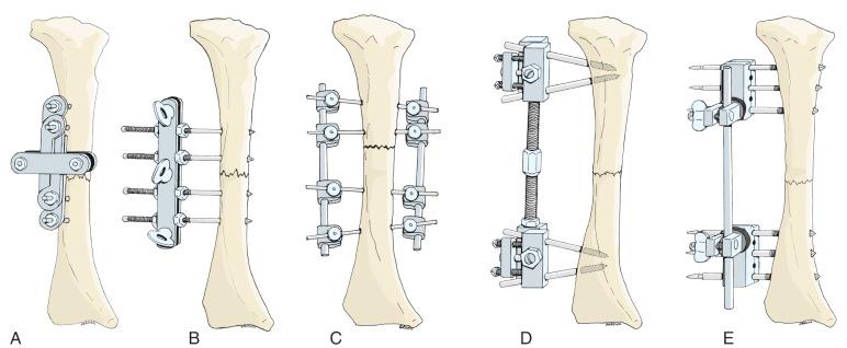
Several of these devices saw use during World War II. Toward the end of that cataclysm, however, the high incidence of complications associated with external fixation became apparent. The major disadvantages noted by a military commission who studied the matter included nerve and vessel injuries by pins, the presence of soft tissue infections at the pin sites, the possibility of ring sequestra and osteomyelitis, and the danger of delayed union or nonunion. Other surgeons were distressed by the mechanical difficulty associated with external fixators, as well as by the prospect of converting a closed fracture to an open fracture. As a consequence, by 1950 most American orthopaedic surgeons were not using mechanical fixators although the pins-in-plaster technique was used for special problems, such as unstable wrist fractures and displaced fractures of the tibia and fibula.
In Europe, conversely, clinical research on external skeletal fixation continued throughout the years during and after World War II. Raoul Hoffmann improved his device, providing a stronger universal joint and an enlarged pin-gripper that held the pins more securely. Charnley, of England, presented his concept of compression arthrodesis of the major joints, using a rather simple skeletal fixator that provided continuous compression of cancellous surfaces of the joint to be fused. In time, the Arbeitsgemeinschaft für Osteosynthesefragen (AO) group of Switzerland modified Charnley's device to more pins in his frame configuration.
Also in France during the 1960s, Jacques Vidal and coworkers used Hoffmann's equipment but designed a quadrilateral frame to provide rigid stabilization of complex fracture problems and septic pseudarthroses under treatment ( Fig. 8.3A ).
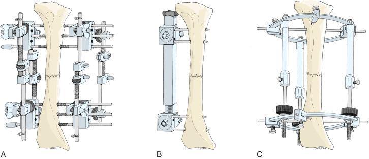
External fixators specifically designed for limb lengthening began to appear after W. V. Anderson developed an apparatus that employed full transcutaneous pins connected to threaded bars. The device permitted gradual distraction of an osteotomized bone. Heinz Wagner, working in Germany, modified Anderson's concept even further, substituting half-pins for Anderson's full pins, while employing a universal distraction bar that patients could lengthen themselves (see Fig. 8.3B ). These pioneers accurately recorded the incidence of complications with their techniques, some of which are unique to limb lengthening.
In Russia, external fixation as a modality for fracture treatment remained viable in the period subsequent to World War II. Surgeons in that country focused attention on ring-type fixators that were connected to the bone by thin transfixion wires tensioned by special wire-gripping clamps. Although these fixators were quite cumbersome, some contained ingeniously geared articulations that permitted precise displacement of the rings in any of three planes independently.
In 1951 Dr. Gavriil A. Ilizarov of Kurgan in the former Soviet Union developed the first model of his transfixion-wire circular fixator, which is still used today (see Fig. 8.3C ). Other Soviet surgeons subsequently designed similar devices, some with geared couplers that allowed gradual repositioning of bone fragments. Within a few years, Ilizarov discovered that bone would form in a widening distraction gap under appropriate conditions of stability, delay, and distraction. His observations and subsequent clinical research revolutionized deformity correction and limb salvage surgery and contributed to a revived worldwide interest in circular external fixation.
Ilizarov's apparatus consists of separate components that can be assembled into an unlimited number of different configurations that allow a surgeon to perform all of the following:
The percutaneous treatment of all closed metaphyseal and diaphyseal fractures, as well as many epiphyseal fractures
The repair of extensive defects of bone, nerve, vessel, and soft tissues without the need for grafting—and in one operative stage
Bone thickening for cosmetic and functional reasons
The percutaneous one-stage treatment of congenital or traumatic pseudarthroses
Limb lengthening or growth retardation by distraction epiphysiolysis or other methods
The correction of long bone and joint deformities, including resistant and relapsed clubfeet
The percutaneous elimination of joint contractures
The treatment of various arthroses by osteotomy and repositioning of the articular surfaces
Percutaneous joint arthrodesis
Elongating arthrodesis—a method of fusing major joints without concomitant limb shortening
The filling in of solitary bone cysts and other such lesions
The treatment of septic nonunion by the favorable effect on infected bone of stimulating bone healing
The filling of osteomyelitic cavities by the gradual collapsing of one cavity wall
The lengthening of amputation stumps
Management of hypoplasia of the mandible and similar conditions
The ability to overcome certain occlusive vascular diseases without bypass grafting
The correction of achondroplastic and other forms of dwarfism
An American orthopaedist David Fischer visited Moscow in 1975 where he obtained several different Soviet circular external fixators. After applying these frames to his own patients, he became concerned with the problems of frame instability associated with transfixion wires, as well as the perceived weight of the circular frames he tried. Thereafter, Fischer developed a circular fixator, which attached to bone via full pins and half-pins. The entire system was originally fabricated from titanium—a lightweight yet strong metal. In general, he noted fewer pin-site infections when his device was mounted with titanium pins instead of steel implants. Moreover, when titanium pin-site sepsis did occur, the reaction was more benign appearing, with far less cellulitis and soft tissue reaction than was commonly observed with steel pins.
North American orthopaedic surgeons, exposed to Ilizarov's methods by Italian practitioners in the mid-1980s, modified Ilizarov's technique. Among the most useful of these improvements has been the fabrication of rings and plates of the Ilizarov apparatus from radiolucent carbon fiber. This material, though more expensive than steel, is substantially lighter and thus popular with the patients.
At Rancho Los Amigos Medical Center, the author and his coworkers began using titanium half-pins (in place of steel wires) to secure Ilizarov's circular fixator to long bones requiring either limb lengthening or deformity correction. In this manner, the adaptability of the circular device was retained, but the problem of muscle impalement and transfixion was reduced, especially in bones such as the ulna or tibia that have large subcutaneous surfaces. In certain anatomic locations, however, wire mounts still appeared superior to pin mountings—especially in the juxtaarticular regions where cancellous bone predominates. For more substantial fragments that include both the articular and metaphyseal regions, combinations of pins and wires have proven successful for mounting circular external skeletal fixation.
Several new fixator configurations have been devised specifically for applications that require anchorage in cancellous bone at one end of the frame and cortical bone on the other. These fixators, which are often referred to as hybrid designs, usually combine an Ilizarov-type ring with an AO-type tubular bar. The tensioned wires are secured to the ring (which surrounds the cancellous portion of the bone) while the bar connects to half-pins in the cortical bone.
Ring fixators have a distinct advantage over unilateral or bilateral devices because the apparatus—especially Ilizarov's device—permits a surgeon to gradually reposition fracture fragments (or osseous fragments after osteotomy) with respect to each other in three-dimensional space. To match this capability, several new unilateral fixators incorporate geared articulations that permit the controlled movement of one pin-gripper with respect to the others.
One modern concept of care for severe polytrauma starts with the application of a simple external fixator for preliminary stabilization of each seriously injured limb, followed by more definitive reconstruction later on. The goal of most surgeons who apply a fixator for the temporary stabilization of a limb is to convert from external fixation to internal fixation, usually an intramedullary nail. The concept is discussed at length later in the section, “Using the Atlas for Damage Control Orthopaedics.”
Although a number of protocols have been recommended to reduce the likelihood of such an infection, one promising concept has been the development of a “pinless” external skeletal fixator by the AO group. With this device, a spring-loaded pair of pins that resemble ice tongs, which grip the cortex but do not penetrate into the endosteal surface, secures bone fragments. In this manner, the medullary canal is (in theory, at least) free of microbial contamination. Time will tell if such an invention reduces the incidence of implant sepsis when an intramedullary nail replaces an external fixator.
A complete understanding of the ideal milieu for rapid fracture healing has yet to be ascertained. Around the world, pioneering clinicians and researchers are using fixators to study the influence of stability, distraction, and compression on fracture healing and regenerate new bone formation. The results of these studies will certainly advance the clinical applications of both internal fixation and external fixation and improve fracture care in general.
When trauma surgeons discovered in the mid-1980s that open fractures could safely be treated with intramedullary nails, it appeared that external fixation's role in orthopaedic surgery would be greatly diminished. Ilizarov's discovery of distraction osteogenesis, however, has rendered the prediction of external fixation's demise premature indeed. Fixators have become an important part of deformity correction, especially where limb elongation is a concomitant requirement. For this reason, worldwide use of external skeletal fixation is on the rise again, as it was before World War II and again in the 1970s and early 1980s.
In the 1990s Dr. Charles Taylor—codeveloper of the Russell-Taylor intramedullary nail—realized that the reduction of a displaced bone fragment (or correction of a deformity) could be accomplished by mathematically defining the path a bone fragment travels as it moves from its displaced position to its corrected position. Using an ingenious design, Taylor connected rings of an Ilizarov-type circular fixator to one another with six struts, each of which could be independently lengthened or shortened ( Fig. 8.4 ). In this way, the relationship between the rings can be altered in a precise manner, modifying the relationship of the rings—and their attached bone fragments—to one another.
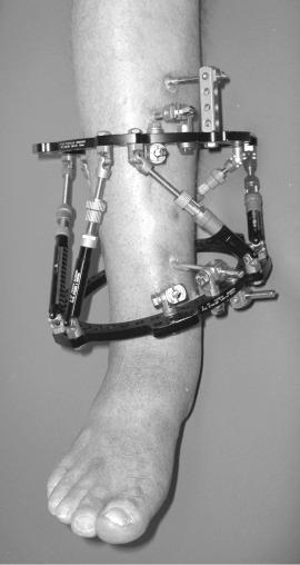
After measuring the precise displacement of the bone fragments and the relationship between the fragments and their respective rings, the data are fed into a computer that has been programmed to determine the pathway to reduction in all planes—angulation, rotation, shortening, and translation. Moreover, the computer program outputs a schedule of strut length changes needed to effect the reduction at whatever predetermined speed is needed for both safety and efficacy. The system, called the Taylor Spatial Frame, is quite popular with surgeons who have become familiar with its use (see ).
Since the previous edition of this book, the patent on the Taylor Spatial Frame's computer interface expired, a fact that has led to the introduction of several hexapod systems with surgeon-friendly computer interfaces, each lauded by its developers and manufacturers as the next step in deformity correction technology. Time will tell if a true advance has occurred.
The disruptive technology in the field of reconstructive limb surgery, however, is the introduction of intramedullary lengthening nails that reliably elongate in response to an externally applied force, either electrical, magnetic, or mechanical. The expanding indications and application of this technology are covered in depth in a separate chapter in this book.
Certain additional developments have occurred since the previous edition of this book. External fixation is now frequently combined with internal fixation to reduce the total time and external fixation frame. This strategy not only reduces patient discomfort and problems with activities of daily living, but also reduces the incidence of pin tract infections, which rises slowly but steadily during the time a fixator is in place. This evolution started with lengthening over an intramedullary nail, a strategy devised in the Baltimore protocol by Paley and coworkers, whereby an intramedullary nail is inserted into a bone after osteotomy for limb elongation. During the same operative session, an external fixator is applied to the limb with care to avoid contact or even close proximity of the transosseous implants with the intramedullary implant. This requires careful fluoroscopy-controlled pin or wire insertion.
Typically, pins or wires are inserted from the posterior to the implant in the femur and tibia, although anterior placement is also acceptable. This strategy is particularly appealing to patients who can have the fixator removed and transverse locking screws inserted into the limb as soon as the distraction phase of the treatment protocol has been completed. Thereafter, ordinary weight bearing, usually with ambulatory aid support to protect the implant, continues until the regenerate bone forms around the implant.
Two comparable strategies have evolved in recent years, both coming from the group at the Hospital for Special Surgery in New York. The first is lengthening and then nailing, a strategy that starts out with a typical Ilizarov-type lengthening that would consist of either a classic ring fixator or a modified ring fixator, such as the Taylor Spatial Frame (particularly if there is concomitant deformity correction), or even a multilateral fixator. Once the deformity is fully corrected and the bone is straight, with early regenerate formation in the distraction gap, an intramedullary nail is inserted and secured with transverse locking screws, and the fixator is removed. Obviously, the transcutaneous transosseous implants must be inserted in a place far enough away from the anticipated medullary canal passage of the nail to prevent contamination by microbes in the pin or wire tract.
Another strategy from the same facility involves the use of external skeletal fixation to achieve length, followed by the use of a plate and screws to shorten the fixator time once the final position of the bone has been achieved. The advent of locking plates makes such a strategy possible, because the plate often has to span a zone where the regenerate new bone is very weak, sometimes only a wispy shadow, thus requiring a particularly strong and stable plate and screw fixation (see ).
With certain kinds of periarticular osteotomies, such as a high tibial osteotomy or distal femoral osteotomy, precise control of the osseous fragments is essential to a successful outcome. Where internal fixation, particularly intramedullary fixation, is employed to secure the fragments, it is helpful to use a temporary external skeletal fixator for alignment after osteotomy, but before inserting the definitive implant. In this case, as with lengthening over a nail or lengthening and then nailing, the transcutaneous transosseous implants must be situated in a way that does not block placement of the definitive hardware. However, unlike situations where the fixator will be left on for some protracted period of time, temporary application of a fixator in the operating room (OR) for alignment purposes does not risk implant-site sepsis where the transcutaneous pins or wires come in contact with the definitive implants. Therefore the technique is particularly appealing where precision is required.
Profound changes in implant technology will soon cause a paradigm shift in the use of external skeletal fixation. Self-lengthening intramedullary nails will stimulate the change. Initially, such devices used mechanical methods to elongate. Specifically, a ratchet mechanism within the device caused the implant to lengthen when the proximal portion of the nail was rotated with respect to the distal portion. Three nails using this strategy, the Bliskunov, the Albizzia, and the intramedullary skeletal kinetic distractor (ISKD), all had the same drawbacks. Because these implants elongated with limb rotation, they would sometimes lengthen too fast, particularly if the patient was too active with the device in place. Conversely, if the distraction proceeded too slowly, early hardening of the regenerate new bone would prevent counterrotation of the fragments, necessitating a return trip to the OR for osteotomy of the regenerate.
The second generation of self-lengthening nails uses internal rotating components and threaded spindles to motor the elongation. In one case, the Fitbone, an electric motor energized through a subcutaneous induction coil, powers the lengthening. A rotating magnet, responding to external magnetic fields, elongates both the Phenix and the Precice intramedullary nails. The devices are so new that a body of literature does not exist yet that supports their use.
These self-lengthening implants allow gradual limb elongation without the use of bulky external skeletal fixation. Likewise, the absence of transcutaneous implants associated with fixators greatly reduces patient discomfort with internal lengthening devices. Moreover, pin tract infections are a thing of the past with self-lengthening nails.
At present, none of the internal lengthening implants can achieve active deformity correction as part of the elongation process. However, a new strategy combining wedge resection and deformity correction (often stabilized with plates and screws) with a self-lengthening nail will eliminate the use of external skeletal fixation for substantial limb deformities. Instead, the deformity will be corrected and secured with internal fixation until the fragments unite. Thereafter, a self-lengthening nail will restore limb length.
Alternatively, implants are being developed that consist of bone plates containing self-lengthening mechanisms, permitting both deformity correction and limb elongation with one operation. Although the cost of such implants may limit their use to the more affluent nations, the ability to simultaneously lengthen and realign a limb without the use of external skeletal fixation is clearly appealing.
What then will be the role of external skeletal fixation when such devices become available? Certainly, damage-control orthopaedics employing temporizing fixators will continue as a strategy for initial trauma management. Likewise, fixator-assisted surgery will continue to play a role where precise correction of a deformity before applying any internal fixation plate or intramedullary nail is required.
A bewildering variety of fixators possessing ingenious articulations and pin-grippers are currently available. Surgical appliance manufacturers continue to add new components and fixator frames to the marketplace at a steady pace, even as the demand for external fixators may diminish in the future. The devices vary considerably in configuration and in technique of frame assembly. The feature common to all fixators, however, is that they are attached to the human body with pins or wires that penetrate the skin and affix to bone. The complications associated with transcutaneous pins are thus common to all past, present, and future fixators, regardless of design or construction. Reducing pin-site sepsis will, more than any other measure, ensure the continued development of external skeletal fixation.
Pin: The term pin refers to that portion of the fixator that penetrates the skin and soft tissues and attaches to bone. In the European literature, pins are sometimes referred to as screws or nails (the distinction resting perhaps on the presence or absence of threads).
Full pin: A full pin is one that protrudes through the skin and soft tissues on both sides of the limb. Such pins are sometimes referred to as transfixion pins or through-and-through pins.
Half-pins: A half-pin is one that penetrates the skin and soft tissues on one side of the limb only and that penetrates bone but does not emerge on the other side of the limb. When inserted, such pins are supposed to penetrate both cortices of the bone but not much beyond the second cortex.
Wire: A thin transosseous implant, usually less than 2 mm in diameter, which is not stiff enough to provide stability to a fixator-bone configuration until tensioned and bolted to the fixator. For this reason, most wires must penetrate the entire limb and be secured to the fixator at both ends.
Olive wire: A wire with a bead somewhere along its length, which prevents the wire from being pulled through the bone. An olive wire can be employed to pull bone fragments into position or to enhance stability of the bone-fixator configuration.
Pin-gripper: The device that holds the pin to the rest of the fixator.
Bar: A part of the apparatus that connects the pin-grippers. Bars may be solid or hollow, smooth or threaded, and they may incorporate a compression-distraction apparatus in their structure.
Ring: A circular bar (or modified bar) that attaches to pin-grippers in a plane that is usually perpendicular to the long axis of the limb. The rings may or may not completely encircle the limb. (Incomplete circles are called half-rings. ) The rings must be connected to each other by bars to create a fixator configuration.
Articulations: A device that connects one bar to another (or a bar to a ring). Some articulations consist of universal joints or hinges, but most do not.
Throughout this chapter, frame configuration terminology modified from Chao and coworkers will be used ( Fig. 8.5 ).
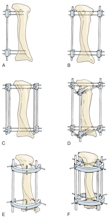
Unilateral: The unilateral frame is one that employs one bar connecting two or more pin-gripping clamps, which are attached to half-pins. It is the simplest configuration. This category includes Parkhill's original bone clamp, Lambotte's external fixator, and the apparatuses devised by Stader, Hoffmann, and Wagner.
Bilateral: A bilateral frame is one that employs a rigid bar on both sides of the limb, connected to full pins that transfix the bone. Roger Anderson's external skeletal fixator was of bilateral design.
Biplanar or multiplanar: A biplanar or multiplanar frame is one that employs pins in two or more planes for increased stability.
Ring: A ring fixator is one that uses transverse bars that completely encircle the limb. Pins transfix the limb and connect to the rings in various locations. Additional bars, as noted earlier, connect the rings to each other. Russian investigators have been using these fixators for many years.
Half-ring: A half-ring fixator is one employing bars that incompletely encircle the limb in a manner similar to the ring fixator.
External fixation systems in which a manufacturer prefabricates the components can be divided into two broad categories: those with fixed configurations and those with variable configurations.
Fixed configuration: These external fixation frames are characterized by a relatively fixed, but usually adjustable, spatial configuration that dictates the position, direction, or number of transcutaneous pins.
Variable configuration: The variable configuration fixator systems are similar to one another in that they consist of many separate components that can be assembled into any spatial configuration as dictated by the nature of the musculoskeletal problem. Precise pin position is generally required only with the individual pins within a cluster (those held by the same pin gripping clamp).
This category comprises systems of external fracture management where transcutaneous pins are connected to an unsolidified substance that hardens within a few minutes after being applied. The classic pins-in-plaster technique, methylmethacrylate external pin fixation, and epoxy-filled tube systems belong in this group. These systems permit unlimited pin positions, but they lack adjustability and preclude compression or distraction.
The application of an external skeletal fixator, especially one that involves the slow repositioning of bone fragments, is different from most other surgical procedures because the “operation” does not end when the patient leaves the OR. Instead, the procedure stretches out over many months, with many clinic visits needed to follow the progress of the bone fragments. As will be evident from the following discussion, pin tract infections, numbness from nerve stretching, delayed union, deviation of mechanical axis during elongation, and numerous other difficulties occur during a typical case. To call all of these challenging events “complications” leads to the conclusion that external fixator applications have a 500% complication rate. Many practitioners who do large numbers of fixator applications use a scheme of analysis popularized by Paley that includes problems, obstacles, and complications. Problems in this paradigm are those difficulties that are correctable in the clinic, often by either a modification of the mounting parameters or a prescription medication. Obstacles are those difficulties that require a return trip to the OR for correction, including repeat osteotomy for premature consolidation, pin or wire replacement for sepsis or loosening, or even a bone graft for tardy bone healing. True complications in this scheme are the permanent sequelae of treatment that adversely compromise the outcome. This includes permanent nerve injury, persistent infection, failure to obtain union, and so forth. This three-level perspective more correctly describes the entire external fixation encounter and allows comparison to other methods of treatment.
Reports of serious neurovascular injury from fixator pins and wires are surprisingly uncommon. In fact, workers reporting large series of external skeletal fixator applications usually note the absence of a significant nerve or vascular injury. However, they are not unheard of, and descriptions of such injuries do appear from time to time in reports dealing with external skeletal fixation.
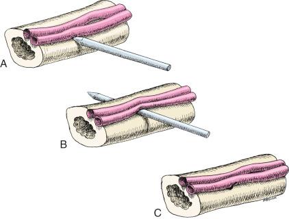
When vascular injuries do occur, they sometimes present in a most peculiar way. A pin directed at a vessel will usually push it to the side without transecting it ( Fig. 8.6A ). As time passes, the vessel, resting against the pin, develops an erosion in its wall. As a result, the patient may suddenly experience bleeding from the implant hole quite some time after fixator application (see Fig. 8.6B ). Alternatively, the pin may create a hole in the side of a vessel, which does not become apparent until the pin is removed. Excessive bleeding through the pinhole may occur (see Fig. 8.6C ), or a false aneurysm may develop in the soft tissues. If the vessel wall necrosis involves an adjacent artery and vein, an arteriovenous fistula may be created shortly after pin removal.
Reports describing serious distal vascular compromise after pin insertion are also rare, perhaps because collateral circulation is usually adequate to sustain the limb. In those few cases where a limb becomes ischemic after pin or wire insertion, severe trauma usually preceded fixator application, suggesting loss of collaterals.
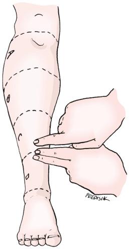
One location in particular may be subject to frequent yet undetected neurovascular injury—the distal lateral tibial surface. In that location, Raimbeau and coworkers analyzed damage to the anterior tibial artery caused by transcutaneous pins. They performed arteriograms on cadaver limbs and determined that the region of the tibia between the lower end of the third quarter and the upper end of the fourth quarter is a danger zone for transfixion pin placement because the anterior tibial artery and deep peroneal nerve lay directly on the tibia's periosteum ( Fig. 8.7 ).
On rare occasions, external fixation pins have been blamed for causing anterior tibial compartment syndrome. Raimbeau and his associates also measured tissue pressures in the anterior compartment after insertion of transcutaneous pins. They determined that the intracompartmental pressure was not significantly elevated after insertion of one transfixion pin, but it more than doubled when a second pin was inserted. Insertion of a third pin did not significantly raise the pressure any higher. Thus they identified two vascular syndromes associated with pin fixation of the lower leg. The first, interference with the distal circulation of the anterior tibial artery, is quite rare because adequate collateral circulation is usually present. The second, anterior compartment syndrome, may also be due to partial occlusion of the anterior tibial artery combined with the increased compartment pressure associated with transfixion pins.
Acute transection of a major nerve is unlikely with external skeletal fixation. Nerves may, however, be nicked during the course of pin insertion, or, more commonly, stretched during limb lengthening or bone transport.
In spite of the relative infrequency of reports of serious neurovascular injury, great care is nevertheless required during pin insertion so that major neurovascular structures are not stretched or damaged. I recommend a skin incision, with observation of major neurovascular bundles, when pins are inserted into certain anatomic areas, such as the lateral humerus or proximal radius. Instead of exposing these structures surgically, however, one can select pin placement positions that avoid the possibility of damage to these structures.
Two difficulties are encountered during pin or wire insertion that could lead to a nerve or vessel injury. First, the surgeon is occasionally unsure of the precise position of a major nerve or vessel with respect to the bone at the level of the limb selected for implant insertion. This confusion arises from the surgeon's orientation to the local anatomy, which usually considers the position of a nerve or vessel in its longitudinal relationship to surgical exposure. Indeed, surgical exposures are purposefully parallel to both the bone and the neurovascular structures in each anatomic region. Second, it is frequently difficult to assess the exact depth to which a pin has penetrated into the bone. This may seem surprising, considering how easy it is to “feel” when a drill bit penetrates the opposite side of a bone during drilling. Nevertheless, because the pin is threaded, there is enough resistance to forward progress to make depth determination difficult.
An atlas showing pin placement positions designed to reduce the likelihood of neurovascular injury from transcutaneous implants appears in this chapter. By recommending pin or wire placement in certain positions, I do not mean to imply that these are the only acceptably safe positions for insertion. At many points in the limb, pins can be safely inserted in several directions that have not been indicated. The descriptions of these positions were omitted for the sake of simplicity and clarity of illustration. With experience (and reference to the atlas), surgeons will find additional pin positions to solve specific clinical problems
In selecting the recommended direction for inserting a pin, I followed several principles designed not only to reduce the incidence of neurovascular injury but also to allow easy, yet solid, pin insertion. First, whenever possible, the pins are inserted perpendicular to the bone surfaces. This facilitates the pin insertion process because it reduces the tendency of the pinpoint to “walk” (slide along the bone surface). The tibia, for example, has a triangular cross section. When the patient is supine, the lateral surface is vertical and the medial surface is oblique. Full pins are more easily inserted from lateral to medial because of this anatomic feature.
Second, pin directions should cross the center of the medullary canal to engage both cortices. When widely separated cortices are engaged by a pin, the tendency of the pin to wobble and loosen is reduced and maximum stability of pin fixation is achieved.
Third, pin insertion into dense bony ridges is to be avoided wherever possible. Drilling into very dense cortical bone with hand tools is tedious and frustrating, tempting the surgeon to try to overcome the resistance by pushing harder and drilling faster, which increases thermal injury to bone and consequently the likelihood of pinhole sepsis.
Fourth, pin positions should have a margin of safety on the opposite side of the bone. A pin is considered “safe” if it passes through the bone and emerges from the opposite side of the limb without encountering a major neurovascular structure. Such pins are illustrated as full (through-and-through) pins, although wires or half-pins could, of course, be safely inserted from either direction.
A pin is labeled “caution” if a major nerve or vascular structure is located on the opposite side of the bone at a distance equal to or greater than the diameter of the bone itself. In this respect, the designation refers only to half-pin placement. A full pin may be labeled caution if the direction or angle of pin insertion is critical to avoid neurovascular injury.
A pin is labeled “danger” if a major neurovascular structure is between one-half and one bone diameter away from the bone on its opposite side. It is wise to insert such pins under radiographic or fluoroscopic control. A pin is also considered a danger pin if it must be inserted adjacent to a neurovascular structure on the near side of the bone. Generally this requires open pin insertion—a longitudinal incision to identify the location of the structure before pin insertion.
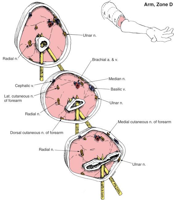
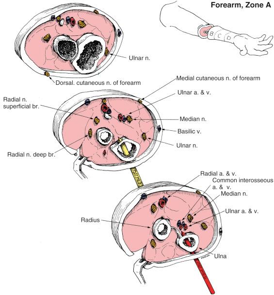
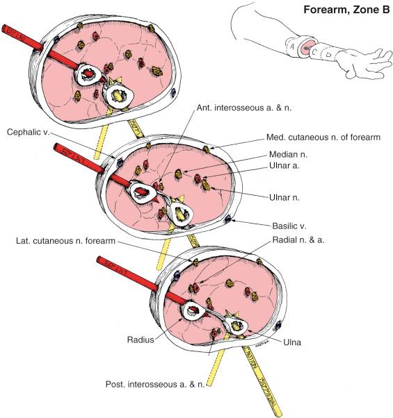
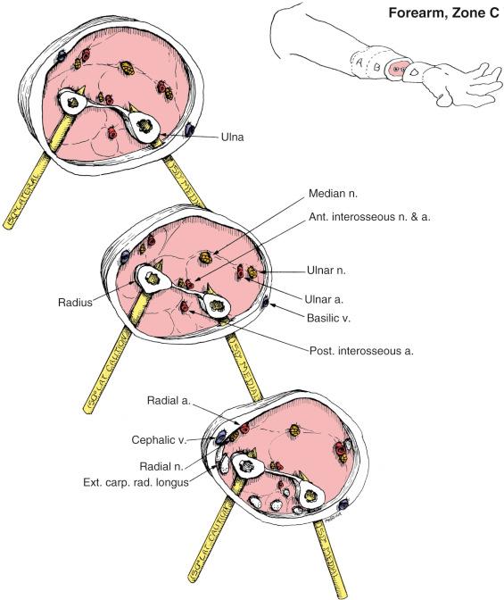
Pin placement is measured in degrees, rotating around the bone from anterior to posterior, with the center of the bone always presumed to be the center of pin placement. Thus the direct anterior position is considered to be 0 degrees, and the direct posterior position is considered to be 180 degrees. Pin placement from directly lateral to directly medial is considered to be 90 degrees lateral and a pin placed from directly medial to directly lateral is considered to be 90 degrees medial. In the forearm where there are two bones available for pin placement, the pin position for each is noted separately. The limb must be in the anatomic position during pin insertion if the atlas is to be used correctly. The humerus should be in neutral rotation, and the forearm supinated to correlate with the location of the anatomic structures indicated.
I recommend image intensification fluoroscopy for pin or wire insertion. The correct assessment of the position and depth of the pin can best be determined if the pin is seen in its true lateral projection. (In the true lateral projection of the pin, the central beam of the x-ray tube must be perpendicular to the pin itself.) At times, there is a tendency by surgeons to judge pin position through use of an oblique projection because a true lateral projection of the pins is difficult to obtain when the patient is supine on a large operating table. The surgeon may have to use considerable ingenuity to position a limb for fluoroscopy with a C-arm image intensifier. It may be necessary, for example, to rotate the limb 45 degrees or more, while rotating the C-arm in the opposite direction to obtain a true lateral projection. To determine the exact location of a pin within a bone, it is necessary to direct the central beam of the x-ray tube along the pin itself. A perfect axial projection of the pin will result in a small circular image equal to the diameter of the pin. In this manner, the position of the pin relative to the cortices can be determined. If roentgenograms rather than fluoroscopy are used, the initial evaluation can be obtained after the first pin is inserted to the presumed proper depth. Before the roentgenogram is taken, it is safer to be too shallow than too deep. If a pin is inserted too deeply, there is the obvious danger to neurovascular structures. Also, “backing out” a pin reduces its fixation in bone. When the depth of the first pin is satisfactory, additional pins of the same length can be inserted to the same depth. This strategy for pin insertion can also be employed to reduce radiograph exposure to the OR personnel when image intensification fluoroscopy is used. Only a brief exposure is necessary to determine the position and depth of the first pin. Thereafter, pins can be inserted to the same depth without checking the progress of each pin individually.
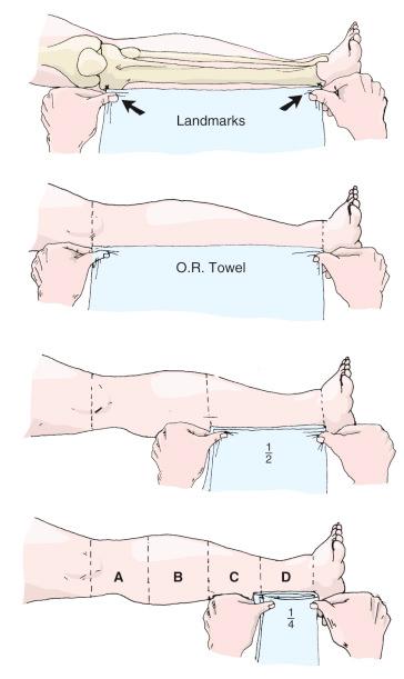
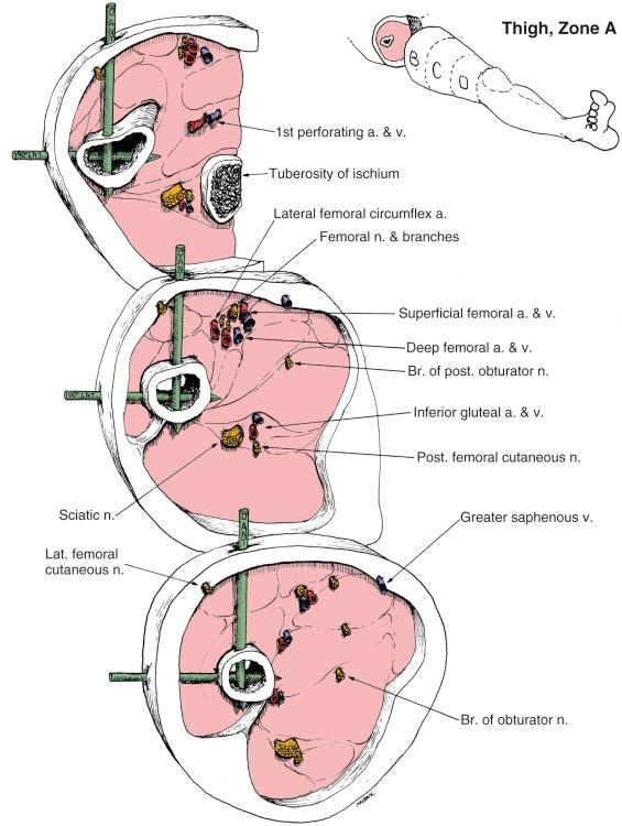
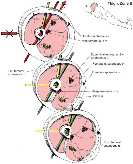
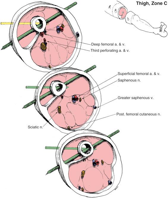
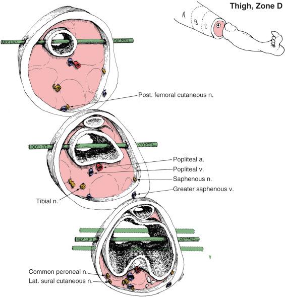
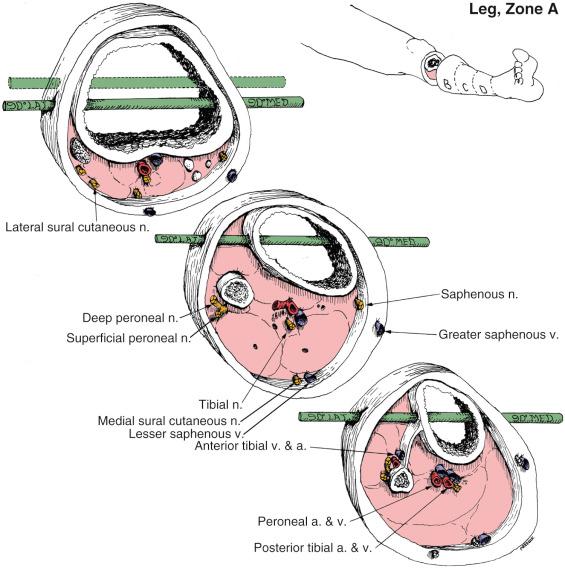
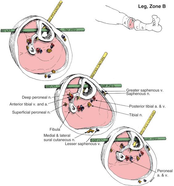
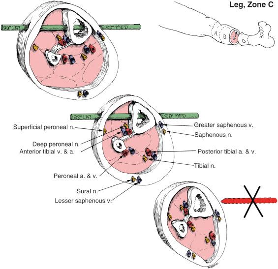
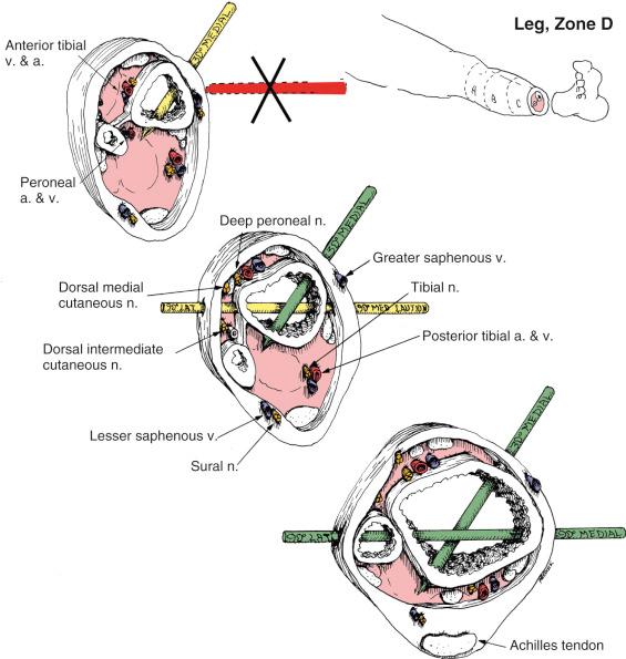
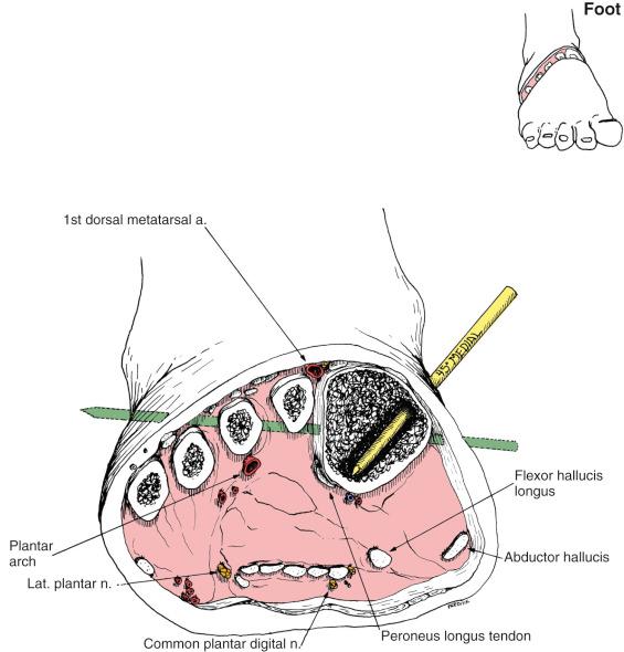
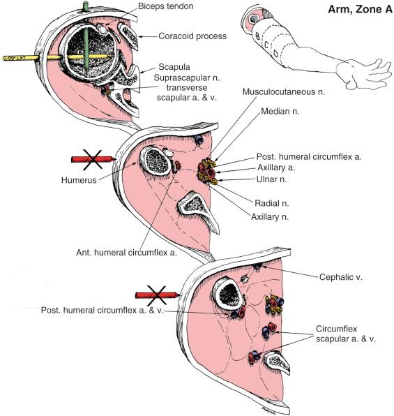
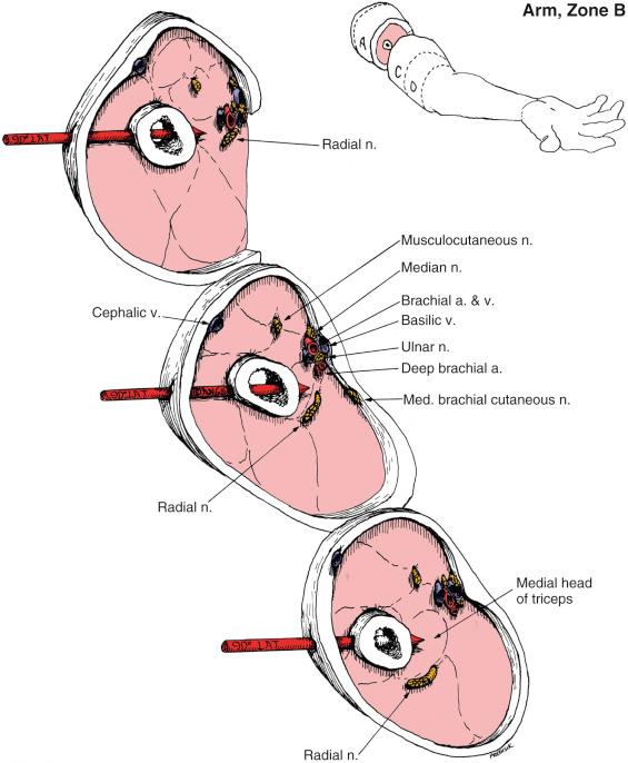
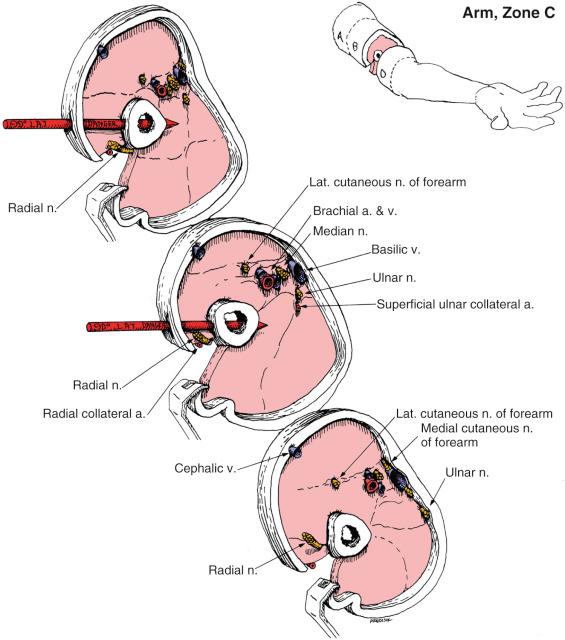
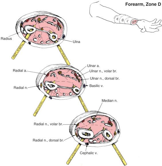
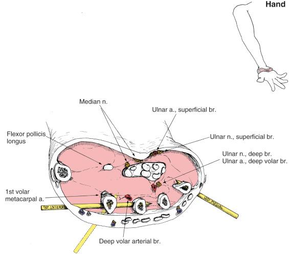
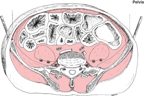
The cross-section atlas in this book was specifically created to aid the surgeon in the OR. Proper orientation of the cross-sectional diagrams to a patient on the operating table depends on the location of easily palpable landmarks. Each limb section in the atlas is treated in an identical manner. Each anatomic area is divided into four equal zones. Palpable bony landmarks identify the upper and lower limits of each anatomic area under consideration.
In the thigh, the proximal bony landmark is the lateral prominence of the greater trochanter of the femur; the distal landmark is the lateral prominence of the lateral epicondyle of the femur.
In the lower leg section, the proximal landmark is the medial tibial joint line; the distal landmark is the medial prominence of the medial malleolus.
In the upper arm, the proximal landmark is the lateral prominence of the greater tuberosity of the humerus, which is one thumb's width below the lateral tip of the acromion process. Distally, the landmark is the lateral epicondyle of the humerus.
In the forearm, the proximal landmark is the lateral prominence of the radial head, which is one thumb's width distal to the lateral epicondyle of the humerus. The distal landmark is the lateral prominence of the radial styloid process.
Each limb segment in the atlas is divided into four zones that are labeled A, B, C, and D, with A proximal and D distal ( Fig. 8.8 ). The zones approximate, but are not exactly, the quarters of each limb segment. The atlas illustrates cross-sectional anatomy in the top, middle, and bottom of each zone. Key diagrams on each plate orient the reader to the zones illustrated. For purposes of clarity, bones, nerves, arteries, and veins have been emphasized in relief. Muscle planes are indicated, but the muscle masses themselves are not labeled. Small cutaneous nerves, veins, and muscular branches of arteries have been omitted. Major arteries are shown with one vein even if they are usually accompanied by two venae comitantes. In the forearm, deep veins have been omitted completely. Some neurovascular structures are emphasized by making them slightly larger than natural size.
Many structures are labeled only once on each page, rather than on each slice. Mental reconstruction of the zone will fill in labels on the unlabeled slices. Unfortunately, some anatomic features are not easily presented in cross-sectional views. These are the transverse vessels and nerves that wind around the bone at one level. Furthermore, the atlas plates do not take into account variations in anatomy that can occur at any level. For these reasons, the atlas illustrations must be considered schematic, rather than representational ( Figs. 8.9–8.27 ).
Pin tract infection has always been the principal drawback to the use of external fixation. Unfortunately, preliminary communications announcing the development of new fixators rarely take note of this complication. Subsequent reports of external fixator applications, however, provide evidence that pin tract infections continue to plague these devices. One problem in determining the overall incidence of pin tract infections is that different authors use different sets of criteria to define pin tract infection. This variance is present even within a single institution, making a review of patients’ charts an inaccurate procedure for determining the incidence of pin tract sepsis.
For this reason, the concept of “major” and “minor” pin tract infection was introduced, followed by other grading systems using numbers or letters. Using such criteria, just about every patient wearing an external fixator for more than a few weeks can expect at least one implant-site infection, something that must be kept in mind when informing a patient about a planned fixator application.
A metallic pin—or most hard foreign substances for that matter—when inserted into the body's tissues will provoke the development of a membrane separating the foreign material from the adjacent tissues. If relative motion is present between the foreign material and the local tissues, a bursal membrane usually forms to secrete lubricating fluid. With a transcutaneous pin, however, the bursal fluid becomes contaminated with microorganisms through the pinhole. Nevertheless, the contamination presents no special problem as long as the pinhole drains freely to the outside. Pinholes become infected when the delicate balance between the patient's natural defenses and the bacteria's infective capability changes. This alteration can result from (1) the development of an abscess (closed space) around the pin; (2) the presence of necrotic tissue in the pinhole, which can become the focus of sepsis; and (3) the presence of excessive motion between a pin and adjacent tissues, which increases fluid production.
As noted earlier, the fluid formed around the pin by the local tissues drains to the external surface and is contaminated with microorganisms in the process. The amount of fluid may be limited, especially when there is no motion between the soft tissues and the implant, such as over the anterior tibia. The fluid dries on the surface, forming a crust. If this crust restricts free drainage of the contaminated bursal fluid by sealing the pinhole, deep abscess formation may result. Thus frequent pin care directed toward removal of the crust from the pin–skin interface reduces pin sepsis.
Necrosis of the skin will occur if the tension (or compression) produced by the pin interferes with the circulation of the local subdermal capillary plexus. Plastic surgeons are mindful of this principle when transposing skin flaps; trauma surgeons using transcutaneous pins for external skeletal fixation must also keep it in mind. Skin tension can occur immediately after implant insertion or whenever a change in alignment or length is made. Skin can also be pinched between pins or wires if they are too close together.
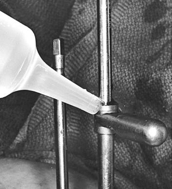
Thermal damage to skin and soft tissues occurs when a high-speed drill bit becomes hot while passing through hard cortical bone, burning tissue as it emerges from the opposite side of a bone. Avoid heat buildup by using a stop/start drilling rhythm and irrigating the drill sleeve while drilling ( Fig. 8.28 ).
Necrosis of deeper soft tissues develops when tissues are compressed by an implant after it has been inserted. Such tension occurs in the anterior compartment of the lower leg if a pin pushes the anterior compartment musculature posteriorly. (It is far wiser to transfix the muscle by pushing the pin straight in, thereby avoiding undue tension.) Necrosis may also be produced if soft tissue “winds up” around a spinning implant or drill bit. (This can best be prevented by the use of a sleeve for both drilling and pin insertion.) Smooth wires will not likely wind up soft tissues, although a spinning bayonet point might do so ( Fig. 8.29 ).
Become a Clinical Tree membership for Full access and enjoy Unlimited articles
If you are a member. Log in here