Physical Address
304 North Cardinal St.
Dorchester Center, MA 02124

Mechanical ventilation (MV) is an important tool for resuscitation of critically ill patients in the emergency department (ED). It is vital that ED practitioners have a thorough understanding of the basics of MV and to know when to apply these principles and how to support patients in respiratory or cardiac failure. Hospital overcrowding has led to a delay in transfer of mechanically ventilated patients out of the ED, and ventilator management often falls on the emergency medicine physician. In addition, during nights and weekends in some facilities, the ED physician may be called on to troubleshoot or stabilize mechanically ventilated patients in the intensive care unit (ICU). The traditional view of MV as a prescription that fits virtually all patients equally should be discarded as a gross misunderstanding of pulmonary pathophysiology. Increasing evidence has shown that the mechanism of lung ventilation by MV may be as deleterious as it is helpful. Because patients remain in the ED while mechanically ventilated, ED clinicians should embrace the established paradigm of pulmonary-protective MV strategies as a cornerstone of care.
Understanding basic pulmonary physiology is essential to understanding how to initiate MV. This ensures that the method of gas delivery meshes with the patient's underlying physiology to avoid ventilator-induced lung injury.
The volume of air that moves in and out of a patient's lungs per minute is termed minute volume (V̇ E ). V̇ E is the product of tidal volume (V t ) and respiratory frequency or rate (f):
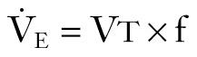
Normal V̇ E is 7 to 10 L/min. V t can be further broken down into alveolar volume (V a ) and dead space volume (V ds ):
In healthy young persons, the anatomic dead space is accounted for by the trachea and the larger airways and is approximately 2.2 mL/kg lean body weight. In disease states, in addition to the anatomic dead space, there is a variable amount of “pathologic” dead space, which corresponds to ventilated alveoli and respiratory bronchioles that are not adequately perfused. The sum of anatomic and pathologic dead space is often referred to as physiologic dead space .
Alveolar minute ventilation (V̇ A ) is the product of rate times V t minus dead space:
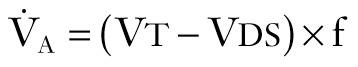
V̇ A and the rate of CO 2 production by the body determine the partial pressure of CO 2 in the alveoli (P aco 2 ), which is approximately equal to systemic arterial CO 2 tension.
Volume and pressure are related for a given respiratory system. A given volume (V) will create a certain pressure (P) relative to the compliance (C) of the respiratory system. The respiratory system consists of the ventilator tubing, endotracheal (ET) tube, trachea, airways, lung parenchyma, chest wall, and diaphragm tension. For example, a 500-mL volume will create a certain pressure based on the compliance of the respiratory system. Increasing the volume will increase the pressure in the system. Decreasing the volume will result in lower pressure. Decreasing the compliance (i.e., making the system “stiffer”) will increase the pressure in the system. Increasing the compliance will decrease the pressure in the system.
Conversely, this relationship also holds for volume. For example, a pressure of 20 cm H 2 O will create a certain volume based on the compliance of the system. Increasing pressure will result in higher volume. Decreasing pressure will result in lower volume. Decreasing compliance will result in lower volume. Increasing compliance will result in higher volume.
Plateau pressure is measured at the end of inspiration with a short breath-hold ( Fig. 8.1 ). At this point no airflow should be occurring. This is considered a static pressure. By understanding the aforementioned volume-pressure relationship, one can easily deduce how plateau pressure is inversely related to respiratory system compliance and directly related to volume. Anything that decreases compliance will increase plateau pressure. Increasing compliance will decrease plateau pressure. Decreasing volume will decrease plateau pressure (a major tenet in lung-protective ventilation).
 measurement. P aw , Airway pressure; PEEP, positive end-expiratory pressure.")
Peak airway pressure is derived during inspiration and thus incorporates airflow. Because there is air movement during this measurement, it is considered a dynamic pressure. It reflects the dynamic compliance of the entire respiratory system and incorporates static compliance and airflow. Peak airway pressure can never be lower than plateau pressure. In addition, because its main distinction is that it incorporates airflow, it is reflective of resistance to airflow. Anything that decreases compliance or increases resistance to airflow will increase peak airway pressure. Increasing compliance or decreasing resistance to airflow will decrease peak airway pressure.
A physiologically appropriate means of detecting and monitoring bronchospasm is the peak-plateau gradient. A normal gradient is less than 4 cm H 2 O pressure, and elevated values indicate increased airway resistance. The efficacy of treatment with β 2 -agonists, steroids, intravenous magnesium, or diuresis may be assessed by monitoring the changes in this gradient ( Fig. 8.2 ).
 with no change in plateau pressure (P plat ) as airflow resistance improves. P aw , Airway pressure.")
Positive end-expiratory pressure (PEEP) is the pressure in the airway at the end of exhalation. PEEP helps keep the large noncartilaginously supported airways and the smaller alveoli open to prevent collapse, atelectasis, and ensuing hypoxia. The ventilation required to compensate for this triad commonly worsens lung compliance and is associated with ventilator-induced lung injury. Progressive increases in PEEP result in elevations in both total lung pressure and total lung volume. For example, serial elevations in PEEP often result in increased plateau pressure and elevated functional residual capacity (FRC; i.e., lung volume).
When discussing MV and PEEP, most often authors are referring to extrinsic PEEP (PEEP e ). This is also referred to as applied PEEP. It is the PEEP that is extrinsically applied by the ventilator. When PEEP is used without a subscript in this chapter, it refers to PEEP e . The useful PEEP range is from 3 to 20 cm H 2 O. PEEP is used to increase FRC and move the zero pressure point of each alveolar unit more proximally in the airway and thereby prevents early alveolar collapse. By so doing, PEEP increases the available number of alveolar units that can participate in gas exchange. The primary effect of PEEP on gas exchange is improvement in oxygenation, not removal of CO 2 . CO 2 clearance is rather efficient and will be well preserved, even in hypoxic situations. By opening one alveolar unit, the tendency of adjacent units is to open as well (i.e., alveolar codependency) ( Fig. 8.3 ). Excessive PEEP will compromise hemodynamics. There are two primary questions to ask when using PEEP to augment oxygenation: (1) What is the “optimal PEEP?” and (2) Is the current amount of PEEP compromising the patient's hemodynamics?

PEEP is not without untoward side effects, and increased levels of PEEP can lead to lung injury and hemodynamic compromise. Increased intrathoracic pressure can result in cardiac compression and collapse, principally of the right atrium. It is imperative that the patient be adequately volume-resuscitated because preload depletion compounds this problem. Desired levels of PEEP simply may not be possible because of deleterious effects on cardiac output.
Optimal PEEP can be determined in several ways. One is to increase PEEP until there are no longer increases in partial pressure of oxygen (P o 2 ). However, this method may result in several untoward events. First, oxygen tension may increase steadily, but carbon dioxide pressure (P co 2 ) may increase as a result of alveolar overdistention. With overdistention, alveolar pressure may exceed pulmonary arteriolar pressure and actually decrease pulmonary blood flow and clearance of CO 2 . Second, alveolar overdistention may increase total intrathoracic pressure and result in diminished venous return and cardiac output. Third, decreased venous return may cause cerebral venous hypertension. The optimal PEEP for one organ system may be deleterious for another. For example, the optimal PEEP for ideal oxygenation may be the worst PEEP for cerebral venous drainage.
An alternative is to increase PEEP until a complication of PEEP occurs (e.g., elevation in P co 2 , hypotension) and then reduce PEEP if needed (inability to tolerate hypercapnia) or expand the patient's intravascular volume to combat the decreased venous return.
Another excellent method of determining the optimal PEEP is guided by assessing changes in plateau pressure with changes in PEEP. As PEEP is increased from a minimal level, the patient's peak airway pressure and plateau pressure will increase by the amount of PEEP e . When the optimal PEEP for the lung units is achieved, plateau pressure will no longer increase. As the lung is optimally recruited, peak and plateau pressure may decrease because more volume of lung is available to receive a set V t . Once this level is exceeded, there will be further increases in plateau pressure beyond the incremental increase in PEEP as the units overdistend. Therefore the clinician must readily identify the plateau in this plateau pressure trend. The same relationship may be displayed graphically in the dynamic pressure-volume loop ( Fig. 8.4 ). The lower limb of the loop represents the pressure required to open the alveolar units. In the absence of PEEP (or inadequate PEEP), this limb is prolonged and flattened and has an inflection point far to the right of the origin of the loop ( Fig. 8.5 ). As PEEP is progressively increased, the inflection point travels to the left. When the optimal PEEP is achieved, there will be a rapid upstroke of the loop because the vast majority of the functional lung units are already open and ready to be ventilated (see Fig. 8.4 ). This strategy is known as the open lung model of MV.
 loop. Note that as soon as pressure is delivered to the airway, there is an increase in measured tidal volume. The lower arrow denotes inspiration and the upper arrow indicates exhalation. This indicates that the airways are open and do not need to be forced open by increasing the pressure in the airway. If this latter case were true, the PV loop would initially be flat along the x-axis.")
 and the pressure-volume loop. Compare this curve with that in Fig. 8.4 . Note that the loop is initially flat (lower segment) along the x-axis. Once airway pressure is high enough to open the alveolar units, each increase in airway pressure is matched by a corresponding increase in tidal volume.")
Irrespective of what technique is used, it is currently widely agreed that plateau pressure should not exceed 30 cm H 2 O. If respiratory system compliance is so low that plateau pressure exceeds 30 cm H 2 O, either PEEP or V t has to be decreased. If this is not possible because of either recalcitrant hypoxia or acidosis, rescue therapies may need to be used (see the section on Acute Lung Injury and Acute Respiratory Distress Syndrome ).
Intrinsic PEEP (PEEP i ) is additional pressure that is generated within the airways from trapped gas that should have been exhaled but for various reasons (commonly obstruction to exhalation such as in chronic obstructive pulmonary disease [COPD]) was not. PEEP i is also referred to as auto-PEEP, dynamic hyperinflation, and breath stacking. For the remainder of this chapter it will be referred to as PEEP i .
PEEP i can cause hemodynamic instability secondary to decreased venous return, just like high levels of PEEP. PEEP i may be detected in two ways: (1) evaluation of the flow-time trace or (2) disconnection of the patient from the ventilator and listening for additional exhaled gas after an exhalation should have occurred. The flow-time trace will demonstrate that the exhalation is not yet completed before the next breath has been initiated ( Fig. 8.6 ).

There are wide-ranging reasons for patients to require MV in the ED, and there are no absolute contraindications. Many time-honored indications for invasive ventilation are now identified as appropriate indications for noninvasive ventilation and are addressed later. Indications for MV range from loss of airway anatomy (edema, direct or indirect trauma, burns, infection), loss of protective airway mechanisms (intoxicants, brain injury, stroke), inability to ventilate, inability to oxygenate, or the expected clinical course. Indications for ET intubation may be separated into several categories—emergency, urgent, delayed, and elective—based on the urgency of establishing a definitive airway.
Perhaps one of the most confusing aspects of MV is the plethora of terms and acronyms that are used. Understanding the basic terminology helps clarify this subject. The following discussion explores machine features and settings. Regardless of which ventilator is used, a limited number of standard features are common to each ( Fig. 8.7 ).
. Selected features common to all ventilators include the respiratory rate ( A ), F io 2 ( B ), positive end-expiratory pressure (PEEP) ( C ), waveform ( D ), inspiratory-to-expiratory ratio (I/E) ( E ), and trigger ( F ).")
Most ventilators allow the clinician to set a respiratory rate. The respiratory rate and actual V t determine a patient's minute ventilation. Patients intubated for airway protection because of trauma or toxicosis often do well with a normal minute ventilation. Initially setting the respiratory rate at 10 to 14 breaths/min and V t at 7 to 8 mL/kg ideal body weight (IBW) is usually sufficient. Adjustments can be made based on arterial blood gas (ABG) analysis, end-tidal CO 2 , or venous blood gas and pulse oximetry. Patients who are septic or have severe acidosis often require higher minute ventilation. Respiratory rates can be increased, as can V t , but volumes higher than 10 mL/kg IBW should not be used because of the risk of inducing ventilator-associated lung injury. In special scenarios such as acute lung injury (ALI) and acute respiratory distress syndrome (ARDS), initial V t values should be lowered to 6 mL/kg IBW within 2 hours of intubation. Some of these specific scenarios are discussed later.
All ventilators can deliver an adjustable fraction of inspired oxygen (F io 2 ). Recommendations are to set it initially at 1.0 because the act of transitioning from negative pressure ventilation (normal physiologic breathing) to positive pressure ventilation (PPV) may unpredictably alter ventilation-perfusion (V̇/Q̇) matching. Although initially an F io 2 of 100% is optimal, it is beneficial to quickly titrate F io 2 down because of the theoretical risk for oxygen toxicity. Make adjustments based on ABG analysis or pulse oximetry, with a goal of keeping arterial P o 2 higher than 60 mm Hg or arterial oxygen saturation (Sa o 2 ) at 88% to 92% to avoid potential oxygen toxicity (see Table 3.3 in Chapter 3 ). Such adjustments may best be accomplished in the ICU rather than the ED, after the entire clinical scenario can be analyzed and all interventions are appropriately adjusted. However, if there is a delay in transfer to the ICU, adjustments should be made in the ED.
PEEP e is typically set at 5 to 8 cm H 2 O. Most patients should be started at a PEEP of 5 cm H 2 O, which is considered a physiologic level. It is used to offset the gradual loss of FRC in supine, mechanically ventilated patients. PEEP can be increased by 2 cm H 2 O every 10 to 15 minutes as needed or tolerated by patients who remain hypoxic. The initial goal is to reduce F io 2 to nontoxic levels. This goal is coming under increasing scrutiny as new information challenges the time frame and concept of O 2 -induced lung injury at F io 2 levels greater than 0.6. Exercise care when using PEEP levels higher than 8 cm H 2 O in the setting of elevated intracranial pressure (ICP), unilateral lung processes, hypotension, hypovolemia, or pulmonary embolism. High PEEP can potentially lead to hypotension as it increases intrathoracic pressure and decreases venous return and, subsequently, cardiac output.
The flow rate is the speed, in liters per minute, that the ventilator is delivering gas. It is found in volume-targeted modes, but not pressure-targeted modes. The flow rate is typically set at 60 L/min, which means that a set V t will be delivered at that speed. Patients wanting higher flow rates will not receive them and may display air hunger. Increase flow rates to deliver the set volume faster and shorten the inspiratory time (thereby increasing the inspiratory-to-expiratory [I/E] time ratio).
The waveform determines how the ventilator delivers the flow of gas. It is traditionally set to a “decelerating waveform” in an effort to optimize recruitment because of different time constants in the lung.
Once the maximal inspiratory flow is reached, the rate of gas delivery immediately begins to slow in a preprogrammed fashion. When compared with the square waveform, longer time is spent in inhalation to deliver the set V t or achieve the target pressure and allow improved oxygenation. This waveform also achieves lower peak airway pressure and higher mean airway pressure.
Once the maximal inspiratory flow rate (IFR) is achieved, gas flow is constant until the set volume is delivered. When that point is reached, gas flow is terminated. This waveform is best for patients with asthma, COPD, and head injury because gas delivered with this waveform allows a longer expiratory time (T e , thereby increasing the I/E time ratio) and lower mean airway pressure. The longer T e is beneficial for patients with restrictive airway disease such as asthma or COPD. Spending a longer time in exhalation allows improved venous drainage from the brain and greater loss of trapped V t . The drawback with this waveform is increased peak airway pressure, which often requires lower V t . This can lead to inadequate alveolar recruitment in patients with ALI.
The ratio of inspiratory time (the time that it takes to take a breath) to expiratory time (the time that it takes to exhale a breath) is automatically reported in some modes, whereas in others it is dialed in.
The normal I/E ratio in a spontaneously breathing, nonintubated patient is 1 : 4. Intubated patients commonly achieve I/E ratios of 1 : 2. Shorter ratios may lead to decreased exhalation by compromising T e . In its extreme form, inverse ratio ventilation (IRV), the normal pattern of breathing is reversed. A longer time is spent in inhalation to allow more time for oxygenation and recruitment. The decrease in T e can lead to air trapping, elevated mean airway pressure, and rising P co 2 . These problems lead to hypercapnia, respiratory acidosis, and PEEP i . ( Fig. 8.8 ).
 and expiratory (T e ) time. Note that as the flow rate changes, there are corresponding alterations in the effective times for inspiration and exhalation. Deflections above the x-axis (time) indicate inspiration, and those below indicate exhalation. The tidal volume (V t ) delivered for each cycle is the same, but T i and T e are different.")
The trigger is the aspect that initiates a machine-generated breath. The trigger can be set to detect either a pressure or a flow gradient. It should be set so that the patient can trigger the ventilator without great effort.
This refers to the sensitivity of the trigger. If the trigger is set too high (not sensitive enough), the work of breathing incurred by the patient can be substantial. Some providers have been known to set the sensitivity at a high level if the patient is markedly overbreathing the set rate. This is not recommended because it causes an undue increase in the work of breathing. Many ventilators are set to a pressure trigger with a sensitivity of 1 to 3 cm H 2 O. If the sensitivity is set too low (too sensitive), the ventilator can “auto-trigger” (inappropriate initiation of machine-generated breaths) because of oscillating water in the ventilator tubing, hyperdynamic heartbeats, or patient movement.
Once some of the standard features are understood, the next step is determining the ventilator's target. Most ventilators can be set to achieve spontaneous breathing, volume-targeted ventilation, pressure-targeted ventilation, or some combination. In volume-targeted ventilation, the ventilator is set to reach a determined volume regardless of the pressure required to do so. Pressure-targeted modes are set to reach a determined pressure regardless of the volume generated. Dual modes combine the benefits of both strategies ( Fig. 8.9 ).

Spontaneously breathing patients can be supported on the ventilator by pressure support ventilation (PSV). In this mode, the ventilator provides a supplemental inspiratory pressure to each of the patient-generated breaths. The clinician sets F io 2 and PEEP. The patient dictates the respiratory rate and generates the desired flow rate. The applied pressure is turned off once the flow decreases to a predetermined percentage. V t is dictated by the pressure support given, patient effort, and compliance of the respiratory system. There is no set respiratory rate, although most modern ventilators have a backup apnea rate.
Volume-cycled ventilation (VCV) may also be termed volume-limited, volume-control, volume-assist, or volume-targeted ventilation. Volume-targeted modes are the most commonly used and the most familiar mode of MV in adults. As its name implies, “volume”—in this case V t —is the ventilator's targeted parameter. With this target, the ventilator seeks to deliver a preset amount of gas. The ventilator will generate the necessary driving pressure to reach this “target.” In addition to V t , the clinician sets the desired respiratory rate, F io 2 , and PEEP. It should be noted that other important aspects of the mechanical ventilator can be controlled in this setting, such as waveform (decelerating or square), I : E ratio, flow rate, trigger, and sensitivity.
The time of gas flow is determined by the set volume, flow rate, and waveform of gas delivery. When the set volume is reached, gas flow is terminated and expiration passively begins. An advantage is that VCV delivers a reliable volume, but it does not take into account dynamic changes in lung compliance, which may alter the ability of the lung to accept delivered gas in gas-exchanging alveoli.
Pressure-cycled ventilation (PCV) may also be termed pressure-limited, pressure-control, pressure-assist, or pressure-targeted ventilation. As its name implies, “pressure” is the ventilator's targeted parameter. The ventilator will generate an inspiratory pressure that has been set by the clinician. With this target, the ventilator alters gas flow to achieve and maintain a preset airway pressure for the duration of a preset inspiratory time (T i ). Gas flow is terminated when the preset pressure is achieved. The volume delivered is determined by the compliance of the patient's respiratory system, airway resistance, T i , and the pressure target. In addition, the clinician sets the desired PEEP, respiratory rate, F io 2 , T i , I : E ratio, and trigger mode. Pressure is maintained with a variable or intermittent flow rate for the set T i . In the setting of hypoxemia, T i may be increased quite precisely to increase mean airway pressure and oxygenation. This strategy is much more difficult, if not impossible, to manipulate with VCV.
An advantage of PCV is that airway pressure is tightly managed to limit or eliminate alveolar overdistention and to reduce ventilator-induced lung injury. It should be noted that the clinician does not control waveform or peak inspiratory flow. Patients can generate their desired flow rate and thus reduce air hunger. Pressure-targeted modes, which are growing in popularity, might have better pressure distribution, improved dissemination of airway pressure, and greater distribution of ventilation.
One problem with PCV is that the volume received by the patient is potentially variable. Any change in system compliance or resistance (or both) will affect the V t generated. For example, if the patient bites on the ET tube or a mucous plug develops, the set pressure that was generating an adequate volume will no longer do so. In contrast, a sudden increase in system compliance might result in the generation of V t that may be considerably larger than desired. Instead of the traditional pressure alarm limits, one must adjust and be cognizant of V t and minute ventilation alarm settings. Uncertainties such as these have led many clinicians to favor volume-targeted strategies or dual-controlled strategies in the acute care setting.
Assist/control (AC) and synchronized intermittent mandatory ventilation (SIMV) are the ventilation modes most commonly used in the ED. Both are acceptable, and no data have demonstrated a better outcome with either mode. Other modes are also acceptable based on clinician preference.
Here, ventilator-initiated breaths, known as machine breaths (i.e., control breaths), are provided at a preset rate. Every breath is fully supported by the ventilator, regardless of whether the breath is initiated by the patient or the ventilator. The clinician sets the base ventilation rate, but if the patient tries to breathe faster than the set rate, additional breaths can be initiated by the patient, known as spontaneous breaths (i.e., assist breaths). A potential downside is inappropriate hyperventilation.
AC modes may be either volume or pressure cycled. Both assist breaths and control breaths will reach the set target, be it a set volume (in a volume-targeted mode) or a set pressure (in a pressure-targeted mode). In VCV, the spontaneous breath receives the same V t that is set for the machine breath. In PCV, the spontaneous breath receives the same pressure that is set for the machine breath. To be more specific, in the volume-targeted mode , the clinician sets V t , as well as the IFR, flow waveform, sensitivity to the patient's respiratory effort (i.e., trigger), and the basal ventilatory rate. In the pressure-targeted mode , the clinician determines the basal ventilatory rate and how sensitive the ventilator will be to the patient's respiratory effort and also selects pressure levels and T i . Hence, in this mode V t is not set by the ventilator but is dependent on the compliance of the lung and chest wall and airway pressure. This helps avoid pressure-induced lung injury, but a specific V t is not guaranteed.
For the patient to trigger the ventilator and initiate flow for a spontaneous breath, mean airway pressure must decrease by a preset amount below PEEP if set on a pressure trigger or flow to be generated if set on a flow trigger. The amount necessary to open the inflow valve is the sensitivity setting.
Caution should be exercised to avoid auto-PEEP (also known as breath stacking) when using volume-targeted AC modes. Because each mechanically delivered breath is given at full V t , patients with a high actual respiratory rate on AC may not have sufficient time to completely exhale between breaths. This results in progressive air trapping, which leads to an increase in auto-PEEP (PEEP i ) (see Fig. 8.6 ). This is of clinical concern in patients with asthma, in whom auto-PEEP can significantly reduce cardiac output and even promote cardiovascular collapse.
SIMV provides breaths at a preset rate (machine breath), similar to the AC mode. The patient can initiate an additional spontaneous breath between the mandated or preset number of ventilator-supported breaths. Such spontaneous breaths above the preset ventilatory rate are not supported by the ventilator, and the patient receives only a spontaneous V t that reflects the depth and time spent in the patient-controlled inspiration. For each of these nonmandatory (i.e., spontaneous) breaths, the patient has a high work of breathing. SIMV is typically partnered with PSV to aid in spontaneous breathing support and to overcome the intrinsic resistance associated with MV. This mode was initially recommended by those who thought that, as a patient's need for mechanical ventilatory support decreased, the set respiratory rate could be decreased and the patient “weaned” to PSV alone and ensuing extubation. Subsequent data have shown that this method of liberation actually increases the number of ventilator days. The synchronized version of intermittent MV allows the ventilator to attempt to coordinate spontaneous and machine breaths to prevent it from delivering a scheduled breath on top of a spontaneous breath or during exhalation after a spontaneous breath. This could lead to elevated mean airway pressure, alveolar overdistention, and biotrauma.
Both volume-targeted ventilation and pressure-targeted ventilation modes can be set to either an AC or SIMV mode to achieve the desired minute ventilation. In a chemically paralyzed patient with no intrinsic respiratory drive, AC and SIMV look virtually identical. Both will reach their target (volume or pressure) at the set rate. If a patient triggers the ventilator at a rate greater than the set rate, these two strategies diverge. In AC, each breath above the set respiratory rate will result in a full mechanically supported breath to reach either the set volume or pressure target. In SIMV, the ventilator will give only the set number of breaths that the clinician has selected. Each additional breath will require the patient to generate a spontaneous V t without mechanical assistance. This patient-generated breath must overcome any resistance caused by the artificial airway and ventilator circuitry. Pressure support should be added to SIMV for patient-generated breaths to reduce any increase in the work of breathing related to the resistance imposed by the ventilator circuit and ET tube.
Become a Clinical Tree membership for Full access and enjoy Unlimited articles
If you are a member. Log in here